JP2005252625A - Image pickup device and image processing method - Google Patents
Image pickup device and image processing method Download PDFInfo
- Publication number
- JP2005252625A JP2005252625A JP2004059845A JP2004059845A JP2005252625A JP 2005252625 A JP2005252625 A JP 2005252625A JP 2004059845 A JP2004059845 A JP 2004059845A JP 2004059845 A JP2004059845 A JP 2004059845A JP 2005252625 A JP2005252625 A JP 2005252625A
- Authority
- JP
- Japan
- Prior art keywords
- image
- conversion
- fisheye
- vibration
- image data
- Prior art date
- Legal status (The legal status is an assumption and is not a legal conclusion. Google has not performed a legal analysis and makes no representation as to the accuracy of the status listed.)
- Withdrawn
Links
Images


Classifications
-
- H—ELECTRICITY
- H04—ELECTRIC COMMUNICATION TECHNIQUE
- H04N—PICTORIAL COMMUNICATION, e.g. TELEVISION
- H04N23/00—Cameras or camera modules comprising electronic image sensors; Control thereof
- H04N23/60—Control of cameras or camera modules
- H04N23/68—Control of cameras or camera modules for stable pick-up of the scene, e.g. compensating for camera body vibrations
-
- H—ELECTRICITY
- H04—ELECTRIC COMMUNICATION TECHNIQUE
- H04N—PICTORIAL COMMUNICATION, e.g. TELEVISION
- H04N23/00—Cameras or camera modules comprising electronic image sensors; Control thereof
- H04N23/60—Control of cameras or camera modules
-
- H—ELECTRICITY
- H04—ELECTRIC COMMUNICATION TECHNIQUE
- H04N—PICTORIAL COMMUNICATION, e.g. TELEVISION
- H04N23/00—Cameras or camera modules comprising electronic image sensors; Control thereof
- H04N23/60—Control of cameras or camera modules
- H04N23/68—Control of cameras or camera modules for stable pick-up of the scene, e.g. compensating for camera body vibrations
- H04N23/681—Motion detection
- H04N23/6811—Motion detection based on the image signal
-
- H—ELECTRICITY
- H04—ELECTRIC COMMUNICATION TECHNIQUE
- H04N—PICTORIAL COMMUNICATION, e.g. TELEVISION
- H04N23/00—Cameras or camera modules comprising electronic image sensors; Control thereof
- H04N23/60—Control of cameras or camera modules
- H04N23/698—Control of cameras or camera modules for achieving an enlarged field of view, e.g. panoramic image capture
Abstract
Description
本発明は、撮像素子を使用して画像情報を取得する撮像装置に関するものであり、特に取得した魚眼画像に対して振れ補正処理を施した透視投影画像を出力する撮像装置に関するものである。 The present invention relates to an imaging apparatus that acquires image information using an imaging element, and more particularly to an imaging apparatus that outputs a perspective projection image obtained by performing shake correction processing on an acquired fisheye image.
魚眼光学系による広角視野の撮像は、監視、遠隔操作、TV会議、内視鏡など様々な分野で利用されている。その特徴は、画角180°以上の超広角視野画像も、その特殊な射影方式により撮像素子の受光面の有限領域に投影可能な点であり、透視投影画像を撮像する通常の撮像装置では理論的に取得できないような超広角視野画像も取得できる点にある。 しかし、魚眼光学系に特有の射影方式は、撮影像の形状を歪ませ、人間が観察する観点では本来の被写体形状との相違が著しい。 Wide-angle visual field imaging using a fish-eye optical system is used in various fields such as monitoring, remote control, TV conference, and endoscope. Its feature is that an ultra-wide-angle field of view image with an angle of view of 180 ° or more can be projected onto a finite region of the light receiving surface of the image sensor by its special projection method. It is also possible to acquire an ultra-wide-angle visual field image that cannot be acquired automatically. However, the projection method peculiar to the fish-eye optical system distorts the shape of the photographed image, and is significantly different from the original subject shape from the viewpoint of human observation.
この問題を解決する手法として、特許文献1には、取得した魚眼画像を透視投影画像に変換し、該変換された画像をディスプレイに表示する装置が提案されている。該特許文献1では、魚眼撮影された半球状視野内の任意の画像領域についてパン・チルト・回転・倍率を指定し、2次元変換マッピングX−MAPおよびY−MAPを用いて座標変換することで全方向性画像観察を可能とする。
As a technique for solving this problem,
また、特許文献2には、魚眼光学系による撮影画像の画像情報密度分布を利用した電子ズームが提案されている。即ち、魚眼光学系により撮像された画像は、その周辺部ほど圧縮率が高く、中央部ほど拡大率が高くなる特性を有する。この特性を利用し、解像度を低下させずに電子ズームを行う。 Patent Document 2 proposes an electronic zoom using an image information density distribution of a captured image by a fisheye optical system. That is, the image captured by the fisheye optical system has a characteristic that the peripheral portion has a higher compression rate and the central portion has a higher enlargement rate. Using this characteristic, electronic zoom is performed without reducing the resolution.
さらに、特許文献3では、魚眼レンズで撮影した広視野領域画像の一部範囲のデータを観察者の頭部の動きに合わせて歪み無く表示可能な装置が提案されている。特に、本特許文献に記載された第3実施例においては、等距離射影方式を有する魚眼レンズで撮影された画像を、平面状に歪み無く表示するための変換処理を行い、さらに撮像装置の振れによる画像振れの補償処理を行う。該補償処理は、画像振れに対応した画素ずれ量が所定画素数(例えば、2画素)分以下のときに行われる。
しかしながら、上記特許文献1にて提案の装置では、入力手段から視野角および倍率を指定し、マイクロコンピュータによって変換式を解き、2次元変換マップに変換テーブルを設定することにより任意の領域にパン・チルト・回転・ズーム機能を得る。したがって、微小な視野角や倍率の変動に対してもその都度変換式を解かなければならないので、マイクロコンピュータの演算負担が大きいという問題がある。
However, in the apparatus proposed in
また、特許文献2にて提案の装置では、魚眼画像の画像情報密度分布を利用して解像度劣化の少ない電子ズーム画像を取得するが、ズーム倍率が高くなるほど手振れなどの装置本体に加わる振動によって画像の乱れが発生し、解像度劣化を生じるという問題がある。 In the device proposed in Patent Document 2, an electronic zoom image with little resolution degradation is acquired using the image information density distribution of the fisheye image. However, as the zoom magnification increases, vibrations applied to the device main body such as camera shake are increased. There is a problem that the image is disturbed and the resolution is deteriorated.
さらに、特許文献3にて提案の装置では、画像振れの補償処理を行う基準として、検出された画素ずれ量と所定画素数とを比較することにより制御されるが、映像振れによる画素ずれ量は、装置本体に加わる振動量とズーム率との関係で決まり、単一の閾値で決定されるものではない。また、手振れによる画像ずれか、パン・チルトのような意図的な視野移動による画像ずれかの判断基準は、固定閾値で決定できるものではなく、意図しない激しい振動による大きな画像ずれや、意図的なゆっくりと視点移動する微小な画像ずれなどが存在する。 Furthermore, in the apparatus proposed in Patent Document 3, as a reference for performing image blur compensation processing, control is performed by comparing the detected pixel shift amount with a predetermined number of pixels. It is determined by the relationship between the amount of vibration applied to the apparatus body and the zoom rate, and is not determined by a single threshold value. In addition, the criteria for determining whether the image is shifted due to camera shake or intentional visual field movement such as pan / tilt cannot be determined by a fixed threshold. There is a minute image shift that slowly moves the viewpoint.
本発明は、魚眼画像を透視投影画像に変換する撮像装置において、少ない演算負担で適正な画像の振れを補正できるようにすることを目的とする。 An object of the present invention is to make it possible to correct an appropriate image shake with a small calculation burden in an imaging apparatus that converts a fisheye image into a perspective projection image.
上記の目的を達成するために、1つの観点としての本発明は、魚眼像を光電変換する撮像素子と、該撮像素子を用いて得られた魚眼画像データの透視投影画像データへの射影変換処理を行う変換手段とを有する撮像装置に関する。該撮像装置は、振動に関する振動情報を得る振動検出手段を有し、変換手段は、該振動情報に基づいて魚眼画像データのうち射影変換処理を行う変換領域をシフトさせる。 In order to achieve the above object, the present invention as one aspect includes an imaging device that photoelectrically converts a fisheye image, and projection of fisheye image data obtained by using the imaging device onto perspective projection image data. The present invention relates to an imaging apparatus having conversion means for performing conversion processing. The imaging apparatus includes a vibration detection unit that obtains vibration information related to vibration, and the conversion unit shifts a conversion area in the fisheye image data in which the projective conversion process is performed based on the vibration information.
本発明によれば、撮像装置本体に加わる振動に応じて、魚眼画像を透視投影画像に変換する領域をシフトさせるので、魚眼像を撮影し、透視投影画像を出力する撮像装置において少ない演算負担で適正な電子防振を実現することができる。 According to the present invention, the region for converting a fisheye image into a perspective projection image is shifted in response to vibration applied to the imaging device body, so that a small amount of computation is performed in an imaging device that captures a fisheye image and outputs a perspective projection image. Appropriate electronic image stabilization can be realized with a burden.
以下、本発明の実施例について図面を参照しながら説明する。 Embodiments of the present invention will be described below with reference to the drawings.
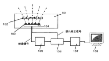
図1には、本発明の実施例1である撮像装置の構成を示している。101は複眼撮像装置であり、複眼光学ユニット102と撮像素子103と画像処理回路104とにより構成されている。
FIG. 1 shows the configuration of an image pickup apparatus that is
複眼光学ユニット102は、それぞれ不図示の被写体からの光束(一点鎖線で示す)を結像する作用を有する複数のレンズがマトリクス状に配列されて構成されている。撮像素子103は、複眼光学系102の各レンズによって結像された被写体像を光電変換する。画像処理回路104は、撮像素子103での光電変換により得られた信号を処理して1つの連続した被写体画像を生成する。
The compound-eye
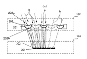
ここで、複眼光学ユニット102および撮像素子103について詳しく説明する。図2(A)には、複眼光学ユニット102の被写体側(前側)の面を示している。また、図3には、複眼光学ユニット102および撮像素子103を側面から見た断面を示している。
Here, the compound eye
複眼光学ユニット102は、マトリクス状に配列された複数(本実施例では、5行5列の計25個)の単レンズ201と、プラスチック等で作られて複数のレンズ201を支持するレンズ支持部材202とから、全体として平板状に構成されている。レンズ支持部材202の前面(図3における上面)うち各レンズ201を保持する部分には、レンズ201を透過した光束を通すための開口部202aが形成されている。レンズ支持部材202における開口部202aの周囲部分は絞りとして機能する。
The compound-eye
図3に示すように、複眼光学ユニット102の中央に配置されたレンズ201の入射側の主光線(一点鎖線で示す)aの方向は、該複眼光学ユニット102の法線方向nに一致している。そして、中央から外側に配置されたレンズ201ほど、その入射側の主光線bが大きく外側に広がるように法線n(中央のレンズ201の主光線a)に対して傾いている。
As shown in FIG. 3, the direction of the principal ray (indicated by the alternate long and short dash line) a on the incident side of the
ここで、中央のレンズ201は、入射側の主光線aと射出側の主光線とが一致するように形成されている。このため、中央のレンズ201の射出側の主光線は、複眼光学ユニット102と平行に配置された撮像素子103に対して垂直になる。
Here, the
一方、中央よりも外側のレンズ201は、入射側の主光線bに対して射出側の主光線が、撮像素子103に対してより垂直に近付く側に屈折するように形成されている。これにより、複眼光学ユニット102をコンパクトにまとめながらも、広い視野角(撮像画角)を得ることができる。
On the other hand, the
なお、レンズ支持部材202の背面(図3における下面)のうち各レンズ201を透過した光束が通過する部分には、開口部202bが形成されている。上記中央のレンズ201に対応する開口部202bは、該中央のレンズ201の背面に正対するよう形成されているが、外側のレンズ201の開口部202bは、これらレンズ201の射出側の光軸の傾き度合い(屈折後の傾き度合い)に応じて、各レンズ201の背面に対して正対する位置よりも中央寄りに位置している。
Note that an
撮像素子103は、CCDセンサ又はC−MOSセンサからなる光電変換素子301と、光電変換素子301の各画素に光を収束させるマイクロレンズ302とから構成されている。光電変換素子301上には、図2(B)に示すように、単レンズ201と同じ数(本実施形態では25個)の光電変換領域103aが形成されており、1つの光電変換領域103aが、対応する1つのレンズ201によって結像された被写体像を光電変換するようになっている。つまり、複眼光学ユニット201の全視野の被写体像は、それぞれ1つのレンズ201と1つの光電変換領域103aとによって構成される複数の撮像系によって分割されて撮像されることになる。
The
図3中に矢印で示す被写体からの光束は、レンズ支持部材202の各開口部202a,202bおよび各レンズ201を通過して、マイクロレンズ302によって集光され、光電変換素子301における各光電変換領域103aの受光面(画素)上で結像する。それぞれのレンズ201の光軸が互いに傾きを持ち、それぞれ個別の視野の像を光電変換素子301の受光面上に結像することにより、全視野を隙間なく撮像することができる。
A light beam from a subject indicated by an arrow in FIG. 3 passes through each of the
また、画像処理回路104は、撮像素子103と一体的に構成され、撮像素子103により光電変換出力された信号に対して画素毎に画像処理を行う。
The
図4には、撮像素子103における1つの光電変換領域103aの構成を示している。この光電変換領域103a内に画像処理回路104が構成されている。
FIG. 4 shows a configuration of one photoelectric conversion region 103 a in the
図中の401は被写体からの光束を受光する画素を構成する光電変換部であり、被写体からの光束を受け、これを電気信号に変換する。402は画素ごとに設けられた演算部であり、メモリや論理演算回路から構成され、光電変換部からの電気信号を画素単位で映像信号に変換処理する。また、各画素の演算部同士は、通信線403によって結線されている。これにより、近傍の画素同士からの映像信号の間での相関的な演算も可能となっており、後述する本装置の振動きに関する情報を映像信号から抽出することができる。
Reference numeral 401 in the figure denotes a photoelectric conversion unit that constitutes a pixel that receives a light beam from a subject, and receives the light beam from the subject and converts it into an electrical signal. An
ここで、複眼光学ユニット102に求められる仕様について説明する。本撮像装置は、通常のビデオカメラに比べてさらに小型の撮像装置であり、例えば、これを携帯する者(使用者)の眼の代わりとなるように制作されたものである。特に子供や老人の衣服等に装着し、迷子や徘徊老人の捜索時、さらには視覚障害者の走行支援などにおいて活用されることを見込んだ撮像装置である。このような使用方法においては、携帯者を取り巻く環境の一部を詳細に観測するよりも、携帯者を取り巻く広い範囲の環境を瞬時に把握できることが重要である。少なくとも、通常、人間が両眼で認知できる視野範囲を携帯者の正面の方向にて撮像する必要がある。
Here, specifications required for the compound-eye
一般に、人間の両眼を合わせた視野範囲は、垂直方向で60度、水平方向で120〜160度と言われていることから、少なくとも水平方向で120〜160度程度の広画角で撮像できるように、複眼光学ユニット102のレンズ201の配列数と光軸の傾きが決定される。
In general, it is said that the visual field range where both eyes of humans are combined is 60 degrees in the vertical direction and 120 to 160 degrees in the horizontal direction, so that an image can be captured with a wide field angle of at least about 120 to 160 degrees in the horizontal direction. As described above, the number of the
一方、人間の全視野範囲が同程度の解像力でないことは良く知られている。具体的には、我々は細かく観察したい対象を視野の中心におき解像度を高くして観ているが、視野範囲周辺では被写体の存在は認識しているものの解像度はあまり高くない。よって本実施例の撮像装置は、複眼光学ユニット102により魚眼像を形成し、これを撮像するものとする。魚眼像は広視野範囲の像であり、視野の中心部は解像度が高く視野角が大きくなるほど解像度が小さくなる特性を持つ。
On the other hand, it is well known that the entire visual field range of humans is not the same resolution. Specifically, we are looking at a subject that we want to observe finely in the center of the field of view with a high resolution, but we recognize the presence of the object around the field of view but the resolution is not very high. Therefore, the imaging apparatus of the present embodiment forms a fish-eye image by the compound-eye
このような複眼光学ユニット102を用いて撮像された魚眼映像の映像信号は、図1に示す1次メモリ105によって記憶保持される。
A fish-eye video signal imaged using such a compound-eye
図5(A)には、複眼光学ユニット102を用いて撮像された魚眼画像の一例を示す。この魚眼画像は、格子状の平面被写体を正射影による射影方式(正弦射影方式)で撮像したものであり、画像中心からの距離に応じてy=f・sinθ の歪みを有する。ここで、yは光軸中心からの距離、fは焦点距離、θは入射角である。
FIG. 5A shows an example of a fish-eye image captured using the compound-eye
なお、本実施例では、y=f・sinθ の魚眼像を撮像するが、それ以外に、等距離射影方式によるy=f・θの魚眼像を透視投影画像に変換するようにしてもよい。 In this embodiment, a fish-eye image with y = f · sin θ is taken, but in addition, a fish-eye image with y = f · θ by the equidistant projection method may be converted into a perspective projection image. Good.
1次メモリ105に記憶保持された魚眼画像データは、射影変換処理部106によって透視投影像に射影変換される。図5(B)には、魚眼画像を透視投影画像に射影変換した画像を示しており、被写体の本来の格子形状が復元されている。実際には、透視投影画像は、映像表示部108に表示されるように矩形領域の画像に変換される。
The fisheye image data stored and held in the
ここで、射影変換処理部106について説明する。前述したように、本実施例では、魚眼像を正射影による射影方式で撮像する。この場合、入射角θで受光される被写体からの光束は、撮像素子103の撮像面上では、y=f・sinθで表される像として結像する。
Here, the projective
一方、透視投影による撮影像は、入射角θで受光される被写体からの光束が、撮像面上でY=F・tanθ (Yは光軸中心からの距離、Fは焦点距離、θは入射角)で表されるように結像する。したがって、魚眼画像を透視投影画像に変換する場合の変換式は、
y=f・sin{tan-1(Y/F)}
で表される。
On the other hand, in a photographic image obtained by perspective projection, a light beam from an object received at an incident angle θ is Y = F · tan θ on the imaging surface (Y is a distance from the center of the optical axis, F is a focal length, and θ is an incident angle. ) To form an image. Therefore, the conversion formula for converting a fisheye image to a perspective projection image is:
y = f · sin {tan −1 (Y / F)}
It is represented by
実際の変換方法については従来様々な方法が提案されている。例えば、特許第3126955号公報では、上記変換式を簡単な構成で実現するためにルックアップテーブルを用いたハードウェアで実現することが示されている。また、特開2002−203237号公報には、ピクセルごとの複雑な計算を回避するため、射影点をジオメトリ演算により算出し、曲面像を平面像に変換する方法が示されている。本実施例においては、上記変換式を用いてもよいし、これ以外のどのような方法を用いてもよい。 Various methods have been proposed for the actual conversion method. For example, Japanese Patent No. 3126955 discloses that the above conversion formula is realized by hardware using a lookup table in order to realize the conversion formula with a simple configuration. Japanese Patent Application Laid-Open No. 2002-203237 discloses a method of calculating a projection point by geometry calculation and converting a curved surface image into a plane image in order to avoid complicated calculation for each pixel. In the present embodiment, the above conversion formula may be used, or any other method may be used.
また、射影変換時に、fをパラメータとすることにより拡大像が得られる。図6(A)は魚眼画像であり、図6(B),(C)には、映像表示部108に表示される、図6(A)の魚眼画像を射影変換して得られる透視投影画像である。ただし、図6(B)の透視投影画像は、図6(A)に示す魚眼像のうち視野範囲601aを映像表示部108のウィンドウサイズに射影変換したものである。一方、図6(C)の透視投影画像は、図6(B)の場合に比べてパラメータfをn倍にして射影変換したものである。この場合、図6(A)の魚眼像における視野範囲602aの領域が射影変換され、図6(C)に示すようなn倍の拡大画像を得ることができる。
Further, an enlarged image can be obtained by using f as a parameter during projective transformation. 6A is a fish-eye image, and FIGS. 6B and 6C are perspective views obtained by projective transformation of the fish-eye image of FIG. 6A displayed on the
以上のように、魚眼画像は射影変換処理部106により透視投影画像に変換され、映像表示部108に表示される。
As described above, the fisheye image is converted into a perspective projection image by the projection
一方、画像処理回路104は、魚眼映像信号を用いて本撮像装置の振れを表す振動情報としての動きベクトルを生成する。図4に示したように、本実施例では、各光電変換部401に対して演算部402が備えられている。このように画像処理回路104が一体化された構成の撮像素子103は、光電変換により得た映像信号を外部の画像処理回路に伝送するプロセスを踏まずに画像処理ができるため、高速な演算処理ができる。
On the other hand, the
本実施例においても、通常のビデオフレームレート(30フレーム/秒)の数倍(例えば、通常の10倍程度の300フレーム/秒)の高フレームレートで撮像し、高速演算を行う。 Also in the present embodiment, imaging is performed at a high frame rate that is several times the normal video frame rate (30 frames / second) (for example, about 300 times the normal video frame rate), and high-speed calculation is performed.
そして、演算部402は、映像信号を一時的に記憶するメモリを有し、連続した2フレーム分の映像信号間でテンプレートマッチング法による動きベクトルの検出(生成)を行う。高速で読み取り、演算することで、本撮像装置の動きに対してフレーム間の移動量が小さくなり、この結果、テンプレートマッチングの探索範囲を小さくできる利点がある。
The
また、魚眼画像に対してテンプレートマッチングする範囲を、視野の周辺部から中心部へと順次移行させていくことで、より効率的な探索ができる。 In addition, a more efficient search can be performed by sequentially shifting the range of template matching to the fisheye image from the peripheral part of the visual field to the central part.
動きベクトルの検出について図7を用いて簡単に説明する。図7(A),(B)はそれぞれ、射影変換後の透視投影画像と撮像素子103により撮像される魚眼画像である。ここで、本撮像装置が上方向に動いたとき、透視投影画像の動きベクトルは、図7(C)
示すように、全領域に一様なベクトルとなる。なお、矢印の方向は動き(振れ)の方向を、矢印の長さは動きの量を表す。そして、視野範囲の全領域について解像度が一様な場合は、テンプレートマッチングによる動きベクトル生成のための探索範囲は、振れ量が大きいほど大きくなる。
The motion vector detection will be briefly described with reference to FIG. 7A and 7B are a perspective projection image after projective transformation and a fisheye image captured by the
As shown, the vector is uniform over the entire area. The direction of the arrow represents the direction of movement (shake), and the length of the arrow represents the amount of movement. When the resolution is uniform for the entire field of view range, the search range for motion vector generation by template matching becomes larger as the shake amount increases.
一方、魚眼像のように中心部から周辺部にいくほど解像度が低くなる場合は、図7(D)に示すように、動きベクトルは周辺部で小さく、中心部で大きくなる。このため、映像の周辺部から動きベクトルを探索していくことで、はじめは探索範囲を小さくし、中心部にいくほど探索範囲を大きくしていくというように、効率的な動きベクトルの検出が行える。 On the other hand, when the resolution decreases from the central part to the peripheral part as in a fish-eye image, the motion vector is small in the peripheral part and large in the central part as shown in FIG. For this reason, efficient motion vector detection can be achieved by searching for motion vectors from the periphery of the video, initially reducing the search range and increasing the search range toward the center. Yes.
また、同じ映像振れであっても、周辺部に比べて中心部ほど大きな動きベクトルを得ることができるということは、中心部ほど高周波な動きまで検出できるという利点もある。したがって、視野周辺部で動き(振れ)の低周波数成分を検出し、視野範囲の中心部で高周波成分を検出することも可能である。 In addition, even if the image shake is the same, the fact that a larger motion vector can be obtained in the central part than in the peripheral part has the advantage that even a high-frequency motion can be detected in the central part. Therefore, it is also possible to detect a low frequency component of motion (shake) in the peripheral part of the visual field and detect a high frequency component in the central part of the visual field range.
このように動きベクトルを検出したあと、動きベクトルに応じた振れ補正量、すなわち射影変換する変換領域のシフト量が射影変換処理部105に送られる。
After detecting the motion vector in this way, the shake correction amount corresponding to the motion vector, that is, the shift amount of the conversion region to be subjected to the projective transformation is sent to the projective
振れ補正量が入力された射影変換処理部105は、図8に示すように、振れ補正量に応じて、変換領域801を基準変換領域802からシフトし、該シフト後の変換領域801内の魚眼画像データの射影変換を行う。
As shown in FIG. 8, the projection
図9には、本撮像装置の動作を示すフローチャートである。この動作は、画像処理回路104および射影変換処理部105において行われる。なお、ここでは、ハードウェア的な動作として説明するが、同様の動作を、CPUに格納した画像処理プログラムにより実行する構成としてもよい。
FIG. 9 is a flowchart showing the operation of the imaging apparatus. This operation is performed in the
まず、ステップ901では、撮像素子103(各撮像領域103a内での光電変換部401)で受光した被写体像を光電変換する。次に、ステップ902では、撮像素子103からの光電変換により得られた電気信号を画像処理回路104(演算部402)でデジタル信号に変換し、魚眼映像を表す映像信号とする。
First, in step 901, a subject image received by the image sensor 103 (photoelectric conversion unit 401 in each image pickup region 103a) is photoelectrically converted. Next, in step 902, an electrical signal obtained by photoelectric conversion from the
次に、ステップ903では、デジタル映像信号に対して映像出力用の処理を施すか、振れ検出のための処理を施すかが選択される。振れ検出のための処理を施す場合には、ステップ908において、演算部402は、該映像信号を用いて動きベクトルを検出する。なお、動きベクトルは、複眼光学ユニット102の各単レンズ201を通して撮像する撮像領域ごとに、1つずつ生成されてもよいし複数の動きベクトルが生成されてもよい。単レンズ201ごとに1つの又は複数の動きベクトルが生成されることにより、全視野範囲では複数の動きベクトルが生成されることになる。
Next, in step 903, it is selected whether to perform video output processing or shake detection processing on the digital video signal. When processing for shake detection is performed, in step 908, the
そして、ステップ909では、これら動きベクトルから本撮像装置の振れ量を推定する。前述したように、本撮像装置のフレームレートは、通常のビデオフレームレート(30フレーム/秒)よりも高速であるため、複数のフレームを用いて振れ量を推定できる。 In step 909, the shake amount of the imaging apparatus is estimated from these motion vectors. As described above, since the frame rate of the imaging apparatus is faster than the normal video frame rate (30 frames / second), the shake amount can be estimated using a plurality of frames.
例えば、本撮像装置のフレームレートを300フレーム/秒としたとき、1/3の100フレームで振れ量を検出し、残りの200フレームで映像用の信号を生成することができる。この場合、振れ量の推定(ステップ909)が100フレーム分に達するまで、受光(ステップ901)、動きベクトルの検出(ステップ908)および振れ量推定(ステップ909)が繰り返される。 For example, when the frame rate of the imaging apparatus is 300 frames / second, the shake amount can be detected in 1/3 of 100 frames, and video signals can be generated in the remaining 200 frames. In this case, light reception (step 901), motion vector detection (step 908), and shake amount estimation (step 909) are repeated until the shake amount estimation (step 909) reaches 100 frames.
また、振れ量推定の確信度を表わす変数を設け、確信度が閾値を越えるまで上記動作を繰り返すようにしてもよい。 Further, a variable representing the certainty factor of the shake amount estimation may be provided, and the above operation may be repeated until the certainty factor exceeds a threshold value.
以上のようにして振れ量が推定されると、該振れ量は振れ補正量(変換領域のシフト量)として射影変換処理部106に出力される。シフト量は、振れ量が大きいほど大きく(小さいほど小さく)なる。そしてこの後、ステップ902でデジタル化された魚眼映像信号には、映像出力用の処理が施される(ステップ903から904に進む)。
When the shake amount is estimated as described above, the shake amount is output to the projective
ステップ904では、魚眼映像信号に対してオートホワイトバランス(AWB)およびオートゲイン補正(AGC)が行われ、また、ステップ905では、複眼光学ユニット102の各単レンズ201によって発生した収差が補正される。そして、ステップ906では、複数の撮像領域103aによって分割撮像された画像が1枚の連続した魚眼画像に合成される。さらに、該魚眼画像は、1次メモリ105に記憶保持される。
In step 904, auto white balance (AWB) and auto gain correction (AGC) are performed on the fish-eye video signal, and in step 905, the aberration generated by each
こうして、合成された魚眼画像データのうちステップ909でシフトされた変換領域のデータは、ステップ907で透視投影画像に射影変換される。そして、該変換領域の透視投影画像データは、図1に示す2次メモリ107に記憶保持された後、映像表示部108に出力される。映像表示部108に表示される透視投影画像は、振れが適正に補正された画像である。
Thus, the transformation area data shifted in step 909 in the combined fisheye image data is projectively transformed into a perspective projection image in step 907. Then, the perspective projection image data of the conversion area is stored and held in the
以上説明したように、本実施例によれば、魚眼画像データから得た撮像装置の振動情報に基づいて、魚眼画像を透視投影画像に射影変換する領域(変換領域)をシフトするので、常時、全視野範囲の魚眼画像を射影変換し、射影変換後の透視投影画像から振動情報に応じて読み出し領域をシフトする場合に比べて、演算負担を軽減しつつ良好な電子防振を行うことができる。 As described above, according to the present embodiment, based on the vibration information of the imaging device obtained from the fisheye image data, the region (conversion region) for projectively converting the fisheye image to the perspective projection image is shifted. Compared to the case where the fisheye image of the entire visual field range is always projectively transformed, and the readout area is shifted according to the vibration information from the perspective projection image after the projective transformation, the electronic image stabilization is performed while reducing the calculation burden. be able to.
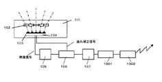
図10には、本発明の実施例2である撮像装置の構成を示している。本実施例の撮像装置は、実施例1の撮像装置に、撮影画像を電送して遠隔地でモニタリングするための圧縮符号化部1001と映像伝送部1002とを追加したものである。
FIG. 10 shows the configuration of an image pickup apparatus that is Embodiment 2 of the present invention. The imaging apparatus according to the present embodiment is obtained by adding a
圧縮符号化部1001は、2次メモリ107から出力された画像データ(透視投影画像データ)の圧縮処理および符号化処理を行う。画像データ(映像信号)の圧縮符号化方式は、現在様々な方法が存在しており、本実施例でも特にその方式を限定しないが、画像の品質を維持しながらなるべく高圧縮符号化を行い、低ビットレートで映像伝送を行える方式を採用することが望ましい。このような圧縮符号化方式としては、動画像の圧縮符号化方式としてMPEG−4やH263があり、また静止画ベースの圧縮符号化方式としてMotion JPEGやMotion JPEG2000などが国際標準規格として代表的な方式である。本実施例でも、これらのいずれかを採用してもよいし、独自方式による圧縮符号化方式を用いてもよい。
The
映像送信部1002は、圧縮符号化された画像データを、遠隔モニタリングのために無線送信する。
The
この送信システムで用いる伝送方式についても特に限定しないが、Wireless LANやIMT-2000を利用した無線通信方式など、伝送範囲に応じた伝送方式を選択することが望ましい。 The transmission method used in this transmission system is not particularly limited, but it is desirable to select a transmission method according to the transmission range, such as a wireless communication method using Wireless LAN or IMT-2000.
本実施例では、人が携帯することを考慮し、省電力を特徴とするBluetooth を例にして説明する。 In the present embodiment, Bluetooth will be described as an example in consideration of being carried by a person.
Bluetooth は、無線周波数2.4GHzで周波数ホッピングスペクトラム拡散通信によって通信し、基本的にはスペクトラム拡散通信である1次変調、拡散変調、送信、受信、逆拡散、情報復調を踏襲しており、1次変調にGFSK、拡散変調に周波数ホッピング方式を採用している。 Bluetooth communicates by frequency hopping spread spectrum communication at a radio frequency of 2.4 GHz, and basically follows primary modulation, spread modulation, transmission, reception, despreading, and information demodulation, which are spread spectrum communication. GFSK is used for next modulation, and frequency hopping is used for spread modulation.
そして、前述したように省電力を特徴とすることから、電池などの消耗も少なく、携帯機器には有効な方式である。 Further, as described above, it is characterized by power saving, so that it consumes less battery and is effective for portable devices.
また、近年では、近距離無線映像伝送方式として“WiMedia” の標準化が進められている。WiMediaでは、1mから50m程度のwireless personal area network (WPAN)における映像伝送を目的としており、本実施例の映像伝送方式として有効である。 In recent years, “WiMedia” is being standardized as a short-range wireless video transmission method. WiMedia is intended for video transmission in a wireless personal area network (WPAN) of about 1 to 50 m, and is effective as a video transmission system of this embodiment.
なお、上記各実施例では、複数のレンズエレメントを配置した複眼光学系により魚眼像を形成する撮像装置について説明したが、本発明は、物体側に単一の魚眼レンズを配置して魚眼像を形成する光学系を備える撮像装置にも適用することができる。以下、その例を説明する。 In each of the above-described embodiments, an imaging apparatus that forms a fisheye image using a compound eye optical system in which a plurality of lens elements are arranged has been described. However, the present invention provides a fisheye image by arranging a single fisheye lens on the object side. The present invention can also be applied to an imaging apparatus including an optical system that forms Examples thereof will be described below.
図11は、本発明の実施例3である撮像装置の構成を示す図である。本実施例の撮像装置は、通常のビデオカメラと同等サイズに撮像装置であって、魚眼レンズを有するものである。 FIG. 11 is a diagram illustrating a configuration of an imaging apparatus that is Embodiment 3 of the present invention. The imaging apparatus of the present embodiment is an imaging apparatus having a size equivalent to that of a normal video camera, and has a fisheye lens.
図11において、1101は被写体の魚眼像を形成する魚眼光学系、1102はCCDセンサやCMOSセンサ等からなる撮像素子(光電変換素子)である。
In FIG. 11,
1103は撮像素子1102から出力された電気信号を画像処理して、映像信号(魚眼映像信号)を生成する画像生成回路である。
画像生成回路1103は、アナログ信号をデジタル信号に変換するA/D変換回路1104と、デジタル信号のレベル補正を行うオートゲイン制御回路(AGC)1105と、映像の白レベル補正を行うオートホワイトバランス回路(AWB)1106と、その他図示しない画像処理回路とを有し、これら回路での処理を通じて上記映像信号としてのデジタル魚眼映像データを生成する。
The
1107および1108は映像信号を1画面分または複数画面分、一時的に記憶保持する第1および第2フィールドメモリ(フィールドメモリ1,2)である。第1フィールドメモリ1107は、画像生成回路1103で生成された映像信号を記憶保持する。また、第2フィールドメモリ1108は、後述する魚眼映像の歪み補正処理(射影変換処理)後の映像信号を記憶保持する。
1109は第1および第2フィールドメモリ1107,1108に対して入出力される映像信号を制御するメモリ制御回路、1111は相互に隣接するビデオフィールドの映像信号から本撮像装置の動き(振動)を検出する動き検出回路である。
動き検出回路1111による検出結果は、後述する射影変換回路1115に伝達される。
A detection result by the
射影変換回路1115は、第1フィールドメモリ1107に保存された魚眼画像データを、透視投影画像データに射影変換する。なお、射影変換回路1115は、後述するように、本撮像装置の振動に伴う映像の振れも補正する。
The
映像出力部1120は、振れ補正が行われた透視投影画像データを順次、図示しない表示デバイスに出力し表示させたり、記録媒体(半導体メモリ、磁気ディスク、光ディスク等)に出力し記録させたりする。1113は、本撮像装置の制御とデータ伝達等を司るコントローラとしてのCPUである。
The
そして、本実施例の撮像装置では、結像した被写体像が撮像素子1102により光電変換され、撮像素子1102からは被写体輝度に応じたアナログ映像信号が出力されて画像生成回路1103に入力される。画像生成回路1103では、A/D変換回路1104によってアナログ映像信号を、例えば14ビットのデジタル信号に変換する。さらにオートゲイン制御回路(AGC)1105およびオートホワイトバランス回路(AWB)1106によって信号レベル補正および白レベル補正が行われた映像信号である魚眼画像データは、第1フィールドメモリ1107に順次一時的に記録保持される。
In the imaging apparatus of the present embodiment, the formed subject image is photoelectrically converted by the
第1フィールドメモリ1107に記憶保持された1フィールド分の魚眼画像データは、これに連続するフィールドの魚眼画像データとともに動き検出回路1111に入力される。また、同時に第1フィールドメモリ1107内の旧フィールドの魚眼画像データは、現フィールドの魚眼画像データに書き換え更新される。以上の動作は、メモリ制御回路1109によって制御される。
The fisheye image data for one field stored and held in the
動き検出回路1111では、連続する2つのフィールドの魚眼画像データのそれぞれにおける複数領域について、テンプレートマッチング法により各領域の動きベクトルを求める。但し、動きベクトルは、テンプレートマッチング法に限るものではなく、勾配法など他の手法によって求めてもよい。
In the
そして、動き検出回路1111は、検出した上記複数領域の動きベクトルを統合し、本撮像装置の振動に対応した振動情報としての動きベクトルを生成する。この動きベクトルは、射影変換回路1115に伝達される。
Then, the
射影変換回路1115は、動きベクトルから振れ補正量としての変換領域シフト量を算出する。そして、第1フィールドメモリ1107に記憶された魚眼画像データのうち透視投影画像データに変換する領域(変換領域)を、実施例1に図8を用いて説明したようにシフトする。さらに、射影変換回路1115は、該シフトした変換領域で射影変換を行い、その結果を2次フィールドメモリ1108を介して、映像出力部1120に出力する。これにより、映像の振れが、演算負担を軽減しつつ、良好に補正される。
The
なお、本実施例においても、上記各動作をコンピュータプログラムとしての画像処理プログラムにより実行してもよい。 Also in this embodiment, the above operations may be executed by an image processing program as a computer program.
また、上記各実施例では、魚眼画像データを用いて撮像装置に加わった振動に関する情報を得る場合について説明したが、振動ジャイロ等のセンサを用いて振動に関する情報を得るようにしてもよい。 In each of the above-described embodiments, the case has been described in which information regarding vibration applied to the imaging apparatus is obtained using fish-eye image data. However, information regarding vibration may be obtained using a sensor such as a vibration gyroscope.
さらに、本発明は、魚眼像を形成する光学系が一体に設けられた撮像装置のみならず、光学系の交換が可能な撮像装置にも適用することができる。 Furthermore, the present invention can be applied not only to an imaging apparatus in which an optical system for forming a fisheye image is integrally provided, but also to an imaging apparatus in which the optical system can be replaced.
101 複眼撮像装置
102 複眼光学ユニット
103,1102 撮像素子
106,1114 射影変換処理部
108 映像表示部
201 レンズ
202 レンズ支持部材
301 光電変換素子
302 マイクロレンズ
401 光電変換部
402 演算部
403 通信線
801,802 射影変換領域
1001 圧縮符号化部
1002 映像送信部
1109 振れ検出部
1117 振れ補正処理部
DESCRIPTION OF
Claims (8)
前記魚眼像を光電変換する撮像素子と、
該撮像素子を用いて得られた魚眼画像データの透視投影画像データへの射影変換処理を行う変換手段と、
該撮像装置に加わった振動に関する振動情報を得る振動検出手段とを有し、
前記変換手段は、前記振動情報に基づいて前記魚眼画像データのうち前記射影変換処理を行う変換領域をシフトさせることを特徴とする撮像装置。 An imaging device capable of capturing fisheye images,
An image sensor that photoelectrically converts the fisheye image;
Conversion means for performing projective conversion processing of the fisheye image data obtained using the imaging element into perspective projection image data;
Vibration detecting means for obtaining vibration information relating to vibration applied to the imaging device;
The image pickup apparatus, wherein the conversion means shifts a conversion area for performing the projective conversion process in the fisheye image data based on the vibration information.
魚眼画像データの透視投影画像データへの射影変換処理を行う変換ステップと、
該撮像装置に加わった振動に関する振動情報を得る振動検出ステップとを有し、
前記変換ステップにおいて、前記振動情報に基づいて前記魚眼画像データのうち前記射影変換処理を行う変換領域をシフトさせることを特徴とする画像処理方法。 An image processing method in an imaging apparatus capable of capturing a fisheye image,
A conversion step for performing projective conversion processing of fisheye image data to perspective projection image data;
A vibration detection step for obtaining vibration information relating to vibration applied to the imaging device;
The image processing method characterized by shifting the conversion area | region which performs the said projection conversion process among the said fisheye image data based on the said vibration information in the said conversion step.
Priority Applications (2)
| Application Number | Priority Date | Filing Date | Title |
|---|---|---|---|
| JP2004059845A JP2005252625A (en) | 2004-03-03 | 2004-03-03 | Image pickup device and image processing method |
| US11/069,258 US7511756B2 (en) | 2004-03-03 | 2005-03-01 | Image-taking apparatus and image processing method |
Applications Claiming Priority (1)
| Application Number | Priority Date | Filing Date | Title |
|---|---|---|---|
| JP2004059845A JP2005252625A (en) | 2004-03-03 | 2004-03-03 | Image pickup device and image processing method |
Publications (2)
| Publication Number | Publication Date |
|---|---|
| JP2005252625A true JP2005252625A (en) | 2005-09-15 |
| JP2005252625A5 JP2005252625A5 (en) | 2007-04-19 |
Family
ID=34909181
Family Applications (1)
| Application Number | Title | Priority Date | Filing Date |
|---|---|---|---|
| JP2004059845A Withdrawn JP2005252625A (en) | 2004-03-03 | 2004-03-03 | Image pickup device and image processing method |
Country Status (2)
| Country | Link |
|---|---|
| US (1) | US7511756B2 (en) |
| JP (1) | JP2005252625A (en) |
Cited By (4)
| Publication number | Priority date | Publication date | Assignee | Title |
|---|---|---|---|---|
| JP2011097217A (en) * | 2009-10-28 | 2011-05-12 | Kyocera Corp | Motion correction device and method therefor |
| JP2013102534A (en) * | 2009-10-14 | 2013-05-23 | Fraunhofer Ges Zur Foerderung Der Angewandten Forschung Ev | Optical image processor |
| JP2013113962A (en) * | 2011-11-28 | 2013-06-10 | Nidec Sankyo Corp | Imaging device with shake correction function |
| WO2021014598A1 (en) * | 2019-07-23 | 2021-01-28 | オリンパス株式会社 | Imaging device, imaging system, image processing device, imaging method, image processing method, and program |
Families Citing this family (21)
| Publication number | Priority date | Publication date | Assignee | Title |
|---|---|---|---|---|
| JP2005252626A (en) * | 2004-03-03 | 2005-09-15 | Canon Inc | Image pickup device and image processing method |
| JP4023494B2 (en) * | 2005-01-18 | 2007-12-19 | ソニー株式会社 | IMAGING DEVICE, IMAGING METHOD, AND IMAGING DEVICE DESIGNING METHOD |
| KR100728818B1 (en) * | 2006-03-03 | 2007-06-19 | 주식회사 대우일렉트로닉스 | Method for detecting optical information, optical information detector and method for sampling data |
| US7858156B2 (en) * | 2006-11-27 | 2010-12-28 | The University Of Massachusetts | Surface buckling method and articles formed thereby |
| JP2008160300A (en) * | 2006-12-21 | 2008-07-10 | Canon Inc | Image processor, and imaging apparatus |
| US8906284B2 (en) * | 2008-05-28 | 2014-12-09 | The University Of Massachusetts | Wrinkled adhesive surfaces and methods for the preparation thereof |
| EP2311256B1 (en) * | 2008-08-04 | 2012-01-18 | Koninklijke Philips Electronics N.V. | Communication device with peripheral viewing means |
| JP5432697B2 (en) * | 2009-12-21 | 2014-03-05 | キヤノン株式会社 | Imaging apparatus and control method thereof |
| US8692867B2 (en) | 2010-03-05 | 2014-04-08 | DigitalOptics Corporation Europe Limited | Object detection and rendering for wide field of view (WFOV) image acquisition systems |
| GB2488519A (en) * | 2011-02-16 | 2012-09-05 | St Microelectronics Res & Dev | Multi-channel image sensor incorporating lenslet array and overlapping fields of view. |
| JP5330439B2 (en) * | 2011-03-18 | 2013-10-30 | 株式会社東芝 | Camera module, image processing apparatus, and image processing method |
| US8723959B2 (en) | 2011-03-31 | 2014-05-13 | DigitalOptics Corporation Europe Limited | Face and other object tracking in off-center peripheral regions for nonlinear lens geometries |
| US8947501B2 (en) | 2011-03-31 | 2015-02-03 | Fotonation Limited | Scene enhancements in off-center peripheral regions for nonlinear lens geometries |
| US8982180B2 (en) | 2011-03-31 | 2015-03-17 | Fotonation Limited | Face and other object detection and tracking in off-center peripheral regions for nonlinear lens geometries |
| US8896703B2 (en) | 2011-03-31 | 2014-11-25 | Fotonation Limited | Superresolution enhancment of peripheral regions in nonlinear lens geometries |
| US20160182822A1 (en) * | 2014-12-19 | 2016-06-23 | Sony Corporation | System, method, and computer program product for determiing a front facing view of and centering an omnidirectional image |
| JP6518115B2 (en) * | 2015-04-13 | 2019-05-22 | キヤノン株式会社 | IMAGE PROCESSING APPARATUS, IMAGING APPARATUS, CONTROL METHOD OF IMAGE PROCESSING APPARATUS, AND PROGRAM |
| WO2017020150A1 (en) * | 2015-07-31 | 2017-02-09 | 深圳市大疆创新科技有限公司 | Image processing method, device and camera |
| JP2018037944A (en) * | 2016-09-01 | 2018-03-08 | ソニーセミコンダクタソリューションズ株式会社 | Imaging control device, imaging apparatus, and imaging control method |
| US11126861B1 (en) * | 2018-12-14 | 2021-09-21 | Digimarc Corporation | Ambient inventorying arrangements |
| CN112346236A (en) * | 2020-11-04 | 2021-02-09 | Oppo广东移动通信有限公司 | Imaging device and electronic apparatus |
Family Cites Families (6)
| Publication number | Priority date | Publication date | Assignee | Title |
|---|---|---|---|---|
| US5185667A (en) * | 1991-05-13 | 1993-02-09 | Telerobotics International, Inc. | Omniview motionless camera orientation system |
| JPH08307753A (en) | 1995-05-09 | 1996-11-22 | Minolta Co Ltd | Video system consisting of camera and display device and display device |
| JP4643773B2 (en) | 1996-12-17 | 2011-03-02 | テセラ・テクノロジーズ・ハンガリー・ケイエフティー | Electronic zoom image input method |
| JP3126955B2 (en) * | 1999-02-12 | 2001-01-22 | 株式会社アドバネット | Arithmetic unit for image conversion |
| JP2002203237A (en) | 2000-08-30 | 2002-07-19 | Usc Corp | Curved image conversion method and recording medium with the curved image conversion method recorded thereon |
| JP2002203254A (en) * | 2000-08-30 | 2002-07-19 | Usc Corp | Curved surface image transforming method and recording medium with the curved surface image transforming method recorded thereon |
-
2004
- 2004-03-03 JP JP2004059845A patent/JP2005252625A/en not_active Withdrawn
-
2005
- 2005-03-01 US US11/069,258 patent/US7511756B2/en not_active Expired - Fee Related
Cited By (5)
| Publication number | Priority date | Publication date | Assignee | Title |
|---|---|---|---|---|
| JP2013102534A (en) * | 2009-10-14 | 2013-05-23 | Fraunhofer Ges Zur Foerderung Der Angewandten Forschung Ev | Optical image processor |
| US8629930B2 (en) | 2009-10-14 | 2014-01-14 | Fraunhofer-Gesellschaft Zur Foerderung Der Angewandten Forschung E.V. | Device, image processing device and method for optical imaging |
| JP2011097217A (en) * | 2009-10-28 | 2011-05-12 | Kyocera Corp | Motion correction device and method therefor |
| JP2013113962A (en) * | 2011-11-28 | 2013-06-10 | Nidec Sankyo Corp | Imaging device with shake correction function |
| WO2021014598A1 (en) * | 2019-07-23 | 2021-01-28 | オリンパス株式会社 | Imaging device, imaging system, image processing device, imaging method, image processing method, and program |
Also Published As
| Publication number | Publication date |
|---|---|
| US20050196068A1 (en) | 2005-09-08 |
| US7511756B2 (en) | 2009-03-31 |
Similar Documents
| Publication | Publication Date | Title |
|---|---|---|
| US7511756B2 (en) | Image-taking apparatus and image processing method | |
| US7834907B2 (en) | Image-taking apparatus and image processing method | |
| US9473725B2 (en) | Image-processing and encoded aperture pattern setting device and method, and image pickup device comprising same | |
| JP4098808B2 (en) | Remote video display method, video acquisition device, method thereof, and program thereof | |
| US8294773B2 (en) | Image capturing apparatus and image processing method | |
| JP4867310B2 (en) | CAMERA, RECORDED IMAGE RECORDING / DISPLAY METHOD, AND PROGRAM | |
| US9807303B2 (en) | Information processing apparatus, information processing method, and program | |
| US9535193B2 (en) | Image processing apparatus, image processing method, and storage medium | |
| CN107850753B (en) | Detection apparatus, detection method, detection program, and imaging apparatus | |
| JP2008225600A (en) | Image display system, image transmitter, image transmission method, image display device, image display method, and program | |
| WO2014208230A1 (en) | Coordinate computation device and method, and image processing device and method | |
| JP2011209620A (en) | Image-processing apparatus and method, and program | |
| WO2014080673A1 (en) | Imaging device and exposure determination method | |
| JP7031280B2 (en) | Image processing equipment, image processing systems and programs | |
| JP6752685B2 (en) | Imaging equipment, imaging methods and programs | |
| JP2010034652A (en) | Multi-azimuth camera mounted mobile terminal apparatus | |
| JP2006184065A (en) | Object detector | |
| JP2004289225A (en) | Imaging apparatus | |
| JP4496883B2 (en) | Image processing method, image processing apparatus, program, and recording medium | |
| JP2009218661A (en) | Imaging device with image distortion correcting function | |
| KR20170011928A (en) | Camera system for compensating distortion of lens using super wide angle camera and Transport Video Interface Apparatus used in it | |
| JPH08305841A (en) | Distorted image correcting display device | |
| JP2004228808A (en) | Photographing device | |
| JP6827778B2 (en) | Image processing equipment, image processing methods and programs | |
| JP2024002631A (en) | Image processing device, imaging apparatus, image processing method, computer program, and recording medium |
Legal Events
| Date | Code | Title | Description |
|---|---|---|---|
| A521 | Request for written amendment filed |
Free format text: JAPANESE INTERMEDIATE CODE: A523 Effective date: 20070305 |
|
| A621 | Written request for application examination |
Free format text: JAPANESE INTERMEDIATE CODE: A621 Effective date: 20070305 |
|
| RD03 | Notification of appointment of power of attorney |
Free format text: JAPANESE INTERMEDIATE CODE: A7423 Effective date: 20081023 |
|
| RD05 | Notification of revocation of power of attorney |
Free format text: JAPANESE INTERMEDIATE CODE: A7425 Effective date: 20081201 |
|
| A761 | Written withdrawal of application |
Free format text: JAPANESE INTERMEDIATE CODE: A761 Effective date: 20090120 |