EP1028338A2 - System and method for interfacing optical fibers with optical communication devices via an optical fiber faceplate - Google Patents
System and method for interfacing optical fibers with optical communication devices via an optical fiber faceplate Download PDFInfo
- Publication number
- EP1028338A2 EP1028338A2 EP00101986A EP00101986A EP1028338A2 EP 1028338 A2 EP1028338 A2 EP 1028338A2 EP 00101986 A EP00101986 A EP 00101986A EP 00101986 A EP00101986 A EP 00101986A EP 1028338 A2 EP1028338 A2 EP 1028338A2
- Authority
- EP
- European Patent Office
- Prior art keywords
- optical
- optical fiber
- faceplate
- communications device
- signals
- Prior art date
- Legal status (The legal status is an assumption and is not a legal conclusion. Google has not performed a legal analysis and makes no representation as to the accuracy of the status listed.)
- Withdrawn
Links
- 230000003287 optical effect Effects 0.000 title claims abstract description 153
- 239000013307 optical fiber Substances 0.000 title claims abstract description 135
- 238000004891 communication Methods 0.000 title claims abstract description 74
- 238000000034 method Methods 0.000 title claims description 15
- 239000000835 fiber Substances 0.000 description 37
- 230000000694 effects Effects 0.000 description 5
- 230000002411 adverse Effects 0.000 description 4
- 239000011521 glass Substances 0.000 description 2
- 238000012986 modification Methods 0.000 description 2
- 230000004048 modification Effects 0.000 description 2
- 238000000926 separation method Methods 0.000 description 2
- 239000012780 transparent material Substances 0.000 description 2
- 241000408659 Darpa Species 0.000 description 1
- 238000005452 bending Methods 0.000 description 1
- 230000005540 biological transmission Effects 0.000 description 1
- 230000008878 coupling Effects 0.000 description 1
- 238000010168 coupling process Methods 0.000 description 1
- 238000005859 coupling reaction Methods 0.000 description 1
- 230000007812 deficiency Effects 0.000 description 1
Images




Classifications
-
- G—PHYSICS
- G02—OPTICS
- G02B—OPTICAL ELEMENTS, SYSTEMS OR APPARATUS
- G02B6/00—Light guides; Structural details of arrangements comprising light guides and other optical elements, e.g. couplings
- G02B6/24—Coupling light guides
- G02B6/42—Coupling light guides with opto-electronic elements
- G02B6/4201—Packages, e.g. shape, construction, internal or external details
- G02B6/4204—Packages, e.g. shape, construction, internal or external details the coupling comprising intermediate optical elements, e.g. lenses, holograms
-
- G—PHYSICS
- G02—OPTICS
- G02B—OPTICAL ELEMENTS, SYSTEMS OR APPARATUS
- G02B6/00—Light guides; Structural details of arrangements comprising light guides and other optical elements, e.g. couplings
- G02B6/24—Coupling light guides
- G02B6/42—Coupling light guides with opto-electronic elements
- G02B6/4201—Packages, e.g. shape, construction, internal or external details
- G02B6/4204—Packages, e.g. shape, construction, internal or external details the coupling comprising intermediate optical elements, e.g. lenses, holograms
- G02B6/421—Packages, e.g. shape, construction, internal or external details the coupling comprising intermediate optical elements, e.g. lenses, holograms the intermediate optical component consisting of a short length of fibre, e.g. fibre stub
-
- G—PHYSICS
- G02—OPTICS
- G02B—OPTICAL ELEMENTS, SYSTEMS OR APPARATUS
- G02B6/00—Light guides; Structural details of arrangements comprising light guides and other optical elements, e.g. couplings
- G02B6/24—Coupling light guides
- G02B6/42—Coupling light guides with opto-electronic elements
- G02B6/4201—Packages, e.g. shape, construction, internal or external details
- G02B6/4249—Packages, e.g. shape, construction, internal or external details comprising arrays of active devices and fibres
-
- G—PHYSICS
- G02—OPTICS
- G02B—OPTICAL ELEMENTS, SYSTEMS OR APPARATUS
- G02B6/00—Light guides; Structural details of arrangements comprising light guides and other optical elements, e.g. couplings
- G02B6/04—Light guides; Structural details of arrangements comprising light guides and other optical elements, e.g. couplings formed by bundles of fibres
- G02B6/06—Light guides; Structural details of arrangements comprising light guides and other optical elements, e.g. couplings formed by bundles of fibres the relative position of the fibres being the same at both ends, e.g. for transporting images
- G02B6/08—Light guides; Structural details of arrangements comprising light guides and other optical elements, e.g. couplings formed by bundles of fibres the relative position of the fibres being the same at both ends, e.g. for transporting images with fibre bundle in form of plate
-
- G—PHYSICS
- G02—OPTICS
- G02B—OPTICAL ELEMENTS, SYSTEMS OR APPARATUS
- G02B6/00—Light guides; Structural details of arrangements comprising light guides and other optical elements, e.g. couplings
- G02B6/24—Coupling light guides
- G02B6/42—Coupling light guides with opto-electronic elements
- G02B6/4292—Coupling light guides with opto-electronic elements the light guide being disconnectable from the opto-electronic element, e.g. mutually self aligning arrangements
Definitions
- the invention generally relates to techniques for interfacing optical fibers with optical fiber communications devices and, in particular, to a system and method for communicating optical signals between an optical fiber and an optical communications device via an optical fiber faceplate.
- a fiber optic ribbon connector typically secures a plurality of optical fibers.
- the fiber optic connector can be coupled to a housing which may include an optical element of transparent material, such as glass for example.
- the optical element couples optical signals between an optical communications device and an optical fiber secured by the fiber optic connector
- the optical communications device can be a laser transmitter for transmitting optical signals, or the optical communications device can be a photodetector capable of receiving optical signals and of converting the received optical signals into electrical signals for further processing.
- the optical communications device is located on a side of the optical element opposite of the fiber optic connector.
- the cores of the optical fibers secured by the fiber optic connector face the optical element and are aligned with the optical communications device (i.e., are aligned with the laser transmitters or photodetectors of the optical communications device). Therefore, optical signals transmitted from the cores of the optical fibers pass through the optical element in the housing and are received by the optical communications device. Also, signals transmitted by the optical communications device pass through the transparent optical element in the housing and are received by the optical fibers secured by the fiber optic connector.
- the housing helps to protect the optical communications device from damage.
- the separation of the optical communications device from the optical fibers secured by the fiber optic connector creates certain problems and difficulties. For example, as known in the art, light tends to diverge as it travels. Therefore, when optical signals are transmitted out of the optical fibers secured by the fiber optic connector, the optical signals diverge (i.e., expand) while the signals travel from the optical fibers to the optical communications device. In many instances where multiple signals are being communicated, this divergence causes the optical signals to overlap and interfere with one another. In addition, the divergence of the optical signal also requires a photodetector with a larger cross-sectional area to capture the entire optical signal.
- some prior art systems utilize ball lenses in or on the optical element of the housing in order to focus the light from the core of each optical fiber secured by the fiber optic connector to the optical communications device and vice versa.
- positioning the components of the system such that the optical signals are appropriately focused can be a difficult and expensive process.
- optical fiber stubs located in the optical element of the housing. Therefore, optical signals communicated with each optical fiber secured by the fiber optic connector pass into a corresponding optical fiber stub in the optical element of the housing. Since each light signal passes through an optical fiber stub in the optical element of the housing, the light signals are prevented from diverging as the signals pass through the optical element.
- each optical fiber secured by the fiber optic connector and the optical communications device should be precisely aligned with an optical fiber stub in the optical elemtent. Achieving such a precise alignment of the optical fiber stubs with the optical communications device and the optical fibers secured by the fiber optic connector can be a difficult process.
- most prior art systems for aligning optical fiber stubs with the optical communications devices and the optical fibers secured by the fiber optic connector include complex and expensive components, thereby increasing the complexity and cost of adequately aligning optical fiber stubs.
- the invention overcomes the inadequacies and deficiencies of the prior art as discussed herein.
- the invention generally provides a system and method for communicating optical signals between optical fibers and optical communications devices via fiber optic faceplates.
- an optical fiber is secured by a fiber optic connector.
- the fiber optic connector is coupled to a housing unit, which is also coupled to a mechanical support.
- the mechanical support is attached to an optical communications device, which is housed and protected by the housing unit.
- a fiber optic faceplate within the housing unit allows optical signals to pass between the optical communications device and the optical fiber secured by the fiber optic connector.
- the faceplate includes an array of small optical fiber segments spaced closely together. Light from an optical signal communicated between the optical communications device and the optical fiber secured by the fiber optic connector is received by the array of optical fiber segments in the faceplate and is transmitted through the faceplate. Therefore, an optical signal is transmitted between the optical communications device and the optical fiber secured by the fiber optic connector via a plurality of optical fiber segments within the faceplate.
- the ends of the optical fiber segments in the faceplate extend in different directions in order to redirect the optical signal into a desirable direction.
- the invention can also be viewed as providing a method for interfacing optical fibers with optical communications devices.
- the method can be broadly conceptualized by the following steps: providing an optical fiber and an optical communications device; positioning a plurality of optical fiber segments between the optical fiber and the optical communications device; communicating an optical signal between the optical fiber and the optical communications device; and simultaneously transmitting the optical signal through each of the plurality of optical fiber segments during the communicating step.
- the invention has many advantages, a few of which are delineated below, as mere examples.
- An advantage of the invention is that optical fibers can be easily and efficiently interfaced with optical communications devices.
- Another advantage of the invention is that adverse effects from the divergence of optical signals can be reduced. Therefore, when multiple signals are being communicated simultaneously in an optical communication system, the interference between these signals can be minimized.
- Another advantage of the invention is that an optical element disposed between an optical fiber and an optical communications device does not need to be precisely aligned with respect to the optical fiber or the optical communications device.
- Another advantage of the invention is that an optical communications device can be housed and protected while a high quality of optical communication is maintained.
- Another advantage of the invention is that the size of a photodetector capable of completely capturing an optical signal can be minimized.
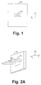
- Fig. 1 is a front view of an optical communications device coupled to a mechanical support.
- Fig. 2A is a three dimensional side view of an interface system having a faceplate in accordance with the invention.
- Fig. 2B is a three dimensional view of the faceplate depicted in Fig. 2A.
- Fig. 3A is a front view of the system depicted by Fig. 2A coupled to the mechanical support of Fig. 1.
- Fig. 3B is a three dimensional side view of the system depicted by Fig. 3A.
- Fig. 3C is a top view of the system depicted by Fig. 3A.
- Fig. 3D is a cross-sectional view of the system depicted by Fig. 3C.
- Fig. 4 is a three dimensional side view of a fiber optic connector.
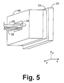
- Fig. 5 is a three dimensional side view of the system depicted by Fig. 3B coupled to the fiber optic connector of Fig. 4.
- Fig. 6A is a side view of optical signals being transmitted through a faceplate of the prior art.
- Fig. 6B is a side view of optical signals being transmitted through the faceplate of Fig. 2B.
- Fig. 7A is a side view of a housing unit of the invention, wherein the optical fibers within the faceplate of the housing unit are bent in order to redirect the optical signals.
- Fig. 7B is a side view of the housing unit of Fig. 8A coupled to a mechanical support which is attached to an optical communications device.
- Fig. 1 shows an optical communications device 25 coupled to a mechanical support 29.
- the optical communications device 25 is designed to communicate optical signals.
- optical communications 25 can include a conventional laser diode for transmitting light signals, or optical communications device 25 can include a conventional photodetector for receiving light signals and for converting the received light signals into electrical signals for further processing.
- Fig. 2A depicts a housing unit 33 configured to engage the mechanical support 29 of Fig. 1 and to protect the optical communications device 25 coupled to the mechanical support 29.
- the housing unit 33 includes a faceplate 35, which is a transparent medium configured to allow optical signals to pass through the housing unit 33.
- Securing members 38 are attached to the housing unit 33 and are configured to engage a fiber optic connector and to secure the fiber optic connector in the y-direction and the z-direction, as will be discussed in further detail below.
- the faceplate 35 is preferably comprised of an array of closely spaced optical fiber segments 42, as depicted by Fig. 2B.
- the optical fiber segments 42 depicted in Fig. 2B extend in the x-direction, thereby exposing the end faces 42a of the optical fiber segments 42.
- the optical fiber segments 42 are preferably much smaller than the standard optical fibers used to transmit light through current communications networks.
- the faceplate 35 is a commercially available product which has been used in many charge coupled device (CCD) applications.
- the housing unit 33 is preferably attached to the mechanical support 29, as depicted by Figs. 3A - 3D. As can be seen by Fig. 3A, the housing unit 33 is preferably positioned on the mechanical support 29 so that the optical communications device 25 is exposed by the transparent faceplate 35. Furthermore, as can be seen by reference to Fig. 3D, the surface of the faceplate 35 is preferably indented with respect to the surface of the housing unit 33 on at least one side. This indention allows the housing unit 33 to engage mechanical support 29 without having the faceplate 35 engage and damage the optical communications device 25. Although the faceplate 35 can be flush with the optical communications device 25 when the housing unit 33 is engaged with the mechanical support 29, it is preferable that there be a small separation between the faceplate 35 and the optical communications device 25 in order to ensure that the optical communications device 25 is not damaged.
- Fig. 4 depicts a fiber optic connector 48.
- the fiber optic connector 48 includes holes 53, which are configured to receive securing members 38 (Fig. 2A).
- the fiber optic connector 48 is designed to secure at least one optical fiber 56 having an optical fiber core exposed at the end 56a of the optical fiber 56.
- the fiber optic connector 48 may include other components (not shown for simplicity) that help to secure the optical fibers 56.
- the optical fibers 56 are preferably conventional optical fibers used by current networks and other systems to transmit optical signals.
- the cores of the optical fibers 56 are preferably larger than the cores of the optical fiber segments 42 in the faceplate 35.
- the cores of the optical fiber segments 42 in the faceplate 35 are approximately on the order of one-eighth in diameter as the cores of the optical fibers 56, although other sizes are also possible.
- the fiber optic connector 48 is designed to engage the housing unit 33, as depicted by Fig. 5.
- the holes 53 of the fiber optic connector 48 (Fig. 4) receive the securing members 38 (Fig. 2A), and the fiber optic connector 48 slides over the securing members 38 until the fiber optic connector 48 engages the housing unit 33.
- the shape of the securing members 38 preferably correspond to the shape of the holes 53 so that the fiber optic connector 48 is secured in the y-direction and the z-direction when the fiber optic connector 48 is engaged with the housing unit 33.
- the securing members 38 are preferably cylinders having a diameter approximately equal to the diameter of the holes 53.
- the positioning of the optical communications device 25, the securing members 38, the holes 53, and the optical fibers 56 is such that the cores of the optical fibers 56 are aligned with the optical communications device 25, when the fiber optic connector 48 is engaged with the housing unit 33.
- One technique for properly aligning the optical fibers 56 with the optical communications device 35 is discussed in copending U.S. patent application entitled “System and Method for Aligning Optical Fibers with Optical Fiber Communications Device," assigned serial no. ( to be determined ) (attorney docket no. 10980925-1) and filed by Rosenberg et al., which is incorporated herein by reference.
- each optical signal is coupled into a plurality of the optical fiber segments 42 within the faceplate 35.
- the coupling of each optical signal into a plurality of optical fiber segments 42 occurs because the optical fiber segments 42 are smaller than the optical fibers 56. Therefore, a plurality of optical fiber segments 42 are located in the area of the faceplate 35 that receives the optical signal.
- light from each optical signal passes through a plurality of the optical fiber segments 42 in the faceplate 35 and is output at the opposite end of the faceplate 35. Because the light from each optical signal is passing through optical fiber segments 42, the optical signals are prevented from diverging as the optical signals pass through the faceplate 35, thereby reducing the effects of cross talk and other adverse effects.
- the transmitters 62 are the cores of the optical fibers within 56, and when the optical signals are being transmitted from the optical communications device 25, the transmitters 62 can be laser transmitters within the optical communications device 25.
- Fig. 6A depicts a faceplate 65 of the prior art where the faceplate 65 is comprised of a transparent material such as glass, for example.
- the faceplate 65 depicted by Fig. 6A does not include the optical fiber segments 42 described above.
- the optical signals 68 diverge as the signals 68 pass through the faceplate 65.
- the divergence of the optical signals 68 eventually causes the signals 68 to overlap resulting in cross talk.
- the divergence of the optical signals 68 is prevented as the signals 68 pass through the faceplate 35 of the invention.
- Fig. 6B shows the feature that light from each optical signal 68 passes through a plurality of optical fiber segments 42 as described above. Since each bit of an optical signal simultaneously passes through a plurality of optical fiber segments 42 within the faceplate 35, the transmitter 62 does not need to be precisely aligned with respect to any single optical fiber segment 42. In this regard, the faceplate 35 can be shifted in the y-direction or the z-direction without affecting the transmission of the optical signals 68 through the faceplate 35. This is because each optical signal 68 couples into whichever of the optical fiber segments 42 are in the path of the light from the optical signal 68.
- each optical signal 68 is transmitted through different optical fiber segments 42, but the path of light for each optical signal 68 remains unchanged.
- the faceplate 35 does have to be precisely aligned with respect to the cores of the optical fibers 56 or to the optical communications device 25.
- the faceplate 35 only should be aligned with the optical communications device 25 and the optical fibers 56 to the extent that at least some portion of the faceplate 35 receives the optical signals 68 from the optical communications device 25 or from the optical fibers 56.
- the optical fibers 56 extend in a different direction than that depicted by Fig. 5. Therefore, the end faces of the optical fibers 56 do not directly face the side of the optical communications device 25 that communicates optical signals. In this situation, it may be desirable for the faceplate 35 to redirect the optical signals 68 as they pass through the faceplate 35 in order to enable communication between the optical communications device 25 and the optical fibers 56.
- Fig. 7A depicts an embodiment of the faceplate 35 that easily redirects optical signals 68 in a different direction (e.g., 90 degrees).
- the faceplate 35, and, hence, the optical fiber segments 42 are bent approximately at a right angle so that the optical signals 68 are output in a direction approximately perpendicular to the direction of input.
- the optical fiber segments 42 will transmit the optical signal 68 through the housing unit 33 and will output the optical signal 68 in the b-direction.
- Fig. 7B shows the housing unit 33 and faceplate 35 depicted in Fig. 7A coupled to a mechanical support 29.
- optical signals received by the faceplate in the a-direction can be easily turned toward the optical communications device 25 ( i.e., turned toward the b-direction).
- Fig. 7B depicts an embodiment where the optical signals are turned about 90 degrees, it should be noted that optical signals 68 can be redirected in other directions by bending the optical fiber segments 42 in different directions. Accordingly, the optical signals 68 received by the faceplate 35 can be output by the faceplate 35 in any desirable direction.
Landscapes
- Physics & Mathematics (AREA)
- General Physics & Mathematics (AREA)
- Optics & Photonics (AREA)
- Optical Couplings Of Light Guides (AREA)
- Optical Fibers, Optical Fiber Cores, And Optical Fiber Bundles (AREA)
Abstract
Description
Claims (10)
- An optical interface system, comprising:an optical fiber (56) including a core;an optical communications device (25); andan array of optical fiber segments (42) positioned between said optical fiber (56) and said optical communications device (25), each of said optical fiber segments (42) including a core with a diameter smaller than a diameter of said core of said optical fiber (56).
- The system of claim 1, wherein:said each of said optical fiber segments (42) respectively has a first end and a second end;said core of said optical fiber (56) faces said first end;said optical communications device (25) faces said second end; andsaid each of said optical fiber segments (42) transmits light received from one of said ends to the other of said ends.
- The system of claim 1 or 2, wherein said first end and said second end extend in different directions.
- The system of one of the preceding claims, wherein parallel ones of said optical fiber segments (42) transmit an optical signal (68).
- An optical interface system, comprising:means (48) for providing an optical signal (68);means (25) for receiving said optical signal (68); andmeans (35) for transmitting said optical signal (68) between said providing means (48) and said receiving means (25), said transmitting means (35) including an array of optical fiber segments (42) simultaneously transmitting said optical signal (68).
- The system of claim 5, wherein:said receiving means (25) includes an optical fiber (56) having a core; andeach of said array of optical fiber segments (42) has a core smaller than said core of said optical fiber (56).
- The system of claim 5 or 6, wherein:said providing means (48) includes an optical fiber (56) having a core; andeach of said array of optical fiber segments (42) has a core smaller than said core of said optical fiber (56).
- The system of one of claims 5 to 7, wherein said array of optical fiber segments (42) changes a direction of said optical signal (68).
- A method for interfacing optical fibers with optical communications devices, comprising steps of:providing an optical fiber (56), an optical communications device (25) and an array of optical fiber segments (42);positioning said array of optical fiber segments (42) between said optical fiber (56) and said optical communications device (25); andsimultaneously transmitting an optical signal (68) through each of said optical fiber segments (42).
- The method of claim 9, further comprising a step of changing the direction of said optical signal (68) during said transmitting step.
Applications Claiming Priority (2)
| Application Number | Priority Date | Filing Date | Title |
|---|---|---|---|
| US248878 | 1999-02-11 | ||
| US09/248,878 US6137929A (en) | 1999-02-11 | 1999-02-11 | System and method for interfacing optical fibers with optical communications devices via an optical fiber faceplate |
Publications (2)
| Publication Number | Publication Date |
|---|---|
| EP1028338A2 true EP1028338A2 (en) | 2000-08-16 |
| EP1028338A3 EP1028338A3 (en) | 2003-10-08 |
Family
ID=22941070
Family Applications (1)
| Application Number | Title | Priority Date | Filing Date |
|---|---|---|---|
| EP00101986A Withdrawn EP1028338A3 (en) | 1999-02-11 | 2000-02-01 | System and method for interfacing optical fibers with optical communication devices via an optical fiber faceplate |
Country Status (3)
| Country | Link |
|---|---|
| US (1) | US6137929A (en) |
| EP (1) | EP1028338A3 (en) |
| JP (1) | JP2000231040A (en) |
Cited By (4)
| Publication number | Priority date | Publication date | Assignee | Title |
|---|---|---|---|---|
| DE10043353A1 (en) * | 2000-08-29 | 2002-03-28 | Infineon Technologies Ag | Coupling element for opto-electronic coupling of an opto-electronic converter with an optical waveguide uses a video disk to connect to guide devices for coupling up optical waveguides |
| US6450701B1 (en) | 2001-05-14 | 2002-09-17 | Schott Optovance, Inc. | Transforming optical fiber interconnect array |
| EP1310811A3 (en) * | 2001-11-13 | 2005-04-06 | Agilent Technologies, Inc. | Optical device, enclosure and method of fabricating |
| CN107894633A (en) * | 2012-11-29 | 2018-04-10 | 深圳迈辽技术转移中心有限公司 | A kind of assemble method of photoelectric conversion device |
Families Citing this family (18)
| Publication number | Priority date | Publication date | Assignee | Title |
|---|---|---|---|---|
| US7087446B2 (en) * | 2000-11-16 | 2006-08-08 | Schott Glas | Method of mounting optoelectronic devices on an optical element and article |
| US7019810B2 (en) | 2001-04-20 | 2006-03-28 | Hewlett-Packard Development Company, L.P. | Fiber faceplate suspended particle display |
| US6910812B2 (en) | 2001-05-15 | 2005-06-28 | Peregrine Semiconductor Corporation | Small-scale optoelectronic package |
| US6674948B2 (en) | 2001-08-13 | 2004-01-06 | Optoic Technology, Inc. | Optoelectronic IC module |
| US6692979B2 (en) | 2001-08-13 | 2004-02-17 | Optoic Technology, Inc. | Methods of fabricating optoelectronic IC modules |
| US6676302B2 (en) | 2001-09-17 | 2004-01-13 | Stratos Lightwave, Inc. | Method of constructing a fiber optics communications module |
| US7056032B2 (en) * | 2001-09-17 | 2006-06-06 | Stratos International, Inc. | Transceiver assembly for use in fiber optics communications |
| US6739760B2 (en) * | 2001-09-17 | 2004-05-25 | Stratos International, Inc. | Parallel fiber optics communications module |
| US7073954B1 (en) | 2001-09-17 | 2006-07-11 | Stratos International, Inc. | Transceiver assembly for use in fiber optics communications |
| US7073955B1 (en) | 2001-09-17 | 2006-07-11 | Stratos International, Inc. | Transceiver assembly for use in fiber optics communications |
| US6729771B2 (en) | 2001-12-17 | 2004-05-04 | Stratos Lightwave, Inc. | Parallel optics subassembly having at least twelve lenses |
| US7212599B2 (en) * | 2002-01-25 | 2007-05-01 | Applied Micro Circuits Corporation | Jitter and wander reduction apparatus |
| US6945708B2 (en) * | 2003-02-18 | 2005-09-20 | Jds Uniphase Corporation | Planar lightwave circuit package |
| JP4043477B2 (en) | 2003-03-13 | 2008-02-06 | 富士通株式会社 | Optical transmission module and manufacturing method thereof |
| JP2005115346A (en) * | 2003-09-17 | 2005-04-28 | Fujitsu Ltd | Optical waveguide structure and optical module |
| US7128476B1 (en) | 2004-08-20 | 2006-10-31 | The United States Of America As Represented By The National Security Agency | Photonic integrated circuit and method of fabricating same |
| JP2006091684A (en) * | 2004-09-27 | 2006-04-06 | Fujitsu Ltd | Optical waveguide structure and optical module |
| JP2007256372A (en) * | 2006-03-20 | 2007-10-04 | Sumitomo Electric Ind Ltd | Optical fiber connection parts |
Family Cites Families (6)
| Publication number | Priority date | Publication date | Assignee | Title |
|---|---|---|---|---|
| US3043179A (en) * | 1958-10-29 | 1962-07-10 | American Optical Corp | Fiber optical image transfer devices |
| GB2086073B (en) * | 1980-10-16 | 1984-02-15 | Marconi Co Ltd | Electro-optical terminations |
| US5293437A (en) * | 1992-06-03 | 1994-03-08 | Visual Optics, Inc. | Fiber optic display with direct driven optical fibers |
| US5329386A (en) * | 1993-04-13 | 1994-07-12 | Hewlett-Packard Company | Fiber-optic faceplate with tilted fibers |
| JP2806737B2 (en) * | 1993-04-28 | 1998-09-30 | シャープ株式会社 | Display device |
| US6203212B1 (en) * | 1998-08-24 | 2001-03-20 | Agilent Technologies, Inc. | Optical subassembly for use in fiber optic data transmission and reception |
-
1999
- 1999-02-11 US US09/248,878 patent/US6137929A/en not_active Expired - Lifetime
-
2000
- 2000-02-01 EP EP00101986A patent/EP1028338A3/en not_active Withdrawn
- 2000-02-03 JP JP2000025797A patent/JP2000231040A/en not_active Withdrawn
Cited By (8)
| Publication number | Priority date | Publication date | Assignee | Title |
|---|---|---|---|---|
| DE10043353A1 (en) * | 2000-08-29 | 2002-03-28 | Infineon Technologies Ag | Coupling element for opto-electronic coupling of an opto-electronic converter with an optical waveguide uses a video disk to connect to guide devices for coupling up optical waveguides |
| US6520688B2 (en) | 2000-08-29 | 2003-02-18 | Infineon Technologies Ag | Coupling element |
| DE10043353B4 (en) * | 2000-08-29 | 2004-04-29 | Infineon Technologies Ag | coupling arrangement |
| US6450701B1 (en) | 2001-05-14 | 2002-09-17 | Schott Optovance, Inc. | Transforming optical fiber interconnect array |
| FR2826129A1 (en) * | 2001-05-14 | 2002-12-20 | Schott Optovance Inc | FIBER OPTIC INTERCONNECTION ELEMENT |
| EP1310811A3 (en) * | 2001-11-13 | 2005-04-06 | Agilent Technologies, Inc. | Optical device, enclosure and method of fabricating |
| US7128474B2 (en) | 2001-11-13 | 2006-10-31 | Avago Technologies Fiber Ip (Singapore) Pte. Ltd. | Optical device, enclosure and method of fabricating |
| CN107894633A (en) * | 2012-11-29 | 2018-04-10 | 深圳迈辽技术转移中心有限公司 | A kind of assemble method of photoelectric conversion device |
Also Published As
| Publication number | Publication date |
|---|---|
| JP2000231040A (en) | 2000-08-22 |
| US6137929A (en) | 2000-10-24 |
| EP1028338A3 (en) | 2003-10-08 |
Similar Documents
| Publication | Publication Date | Title |
|---|---|---|
| US6137929A (en) | System and method for interfacing optical fibers with optical communications devices via an optical fiber faceplate | |
| US9341828B2 (en) | Multi-core fiber optical coupling elements | |
| US7665910B2 (en) | Positioning plate for optical subassembly | |
| US7263256B2 (en) | Optical connection block, optical module, and optical axis alignment method using the same | |
| CN110582712B (en) | Fiber Optic Modules with Integrated Lenses | |
| RU2638979C1 (en) | Hermetic assembly for alignment of optical fibre, which has integrated optical element | |
| US7665911B2 (en) | Optical waveguide holding device and optical transceiver | |
| US20210149128A1 (en) | Multi-fiber interface apparatus for photonic integrated circuit | |
| EP2666044B1 (en) | An optical communication module, and a method for mounting an optical communications system | |
| US5579426A (en) | Fiber image guide based bit-parallel computer interconnect | |
| KR20040034387A (en) | Optical backplane array connector | |
| US20050135742A1 (en) | Coupler assembly for an optical backplane system | |
| EP3268787B1 (en) | Cable connector retention design | |
| US6408121B1 (en) | Optical communication module | |
| US5073000A (en) | Optical interconnect printed circuit structure | |
| US7430375B2 (en) | Optical transceiver | |
| US6219477B1 (en) | Multiport single path optical system and associated method | |
| JPH05113519A (en) | Optical connector | |
| US20040161240A1 (en) | Module having two bi-directional optical transceivers | |
| US8200096B2 (en) | Optical transceiver | |
| US7031576B2 (en) | Connectorized silicon bench for passively aligning optical fibers | |
| US20060093282A1 (en) | Method and apparatus for providing connector keying and identification for unidirectional fiber cables | |
| US8636426B2 (en) | Photoelectric conversion system with optical transceive module | |
| US6488418B2 (en) | Optoelectronic coupling element and production method | |
| CA2359002A1 (en) | Optoelectric module for multi-fiber arrays |
Legal Events
| Date | Code | Title | Description |
|---|---|---|---|
| PUAI | Public reference made under article 153(3) epc to a published international application that has entered the european phase |
Free format text: ORIGINAL CODE: 0009012 |
|
| AK | Designated contracting states |
Kind code of ref document: A2 Designated state(s): AT BE CH CY DE DK ES FI FR GB GR IE IT LI LU MC NL PT SE |
|
| AX | Request for extension of the european patent |
Free format text: AL;LT;LV;MK;RO;SI |
|
| RAP1 | Party data changed (applicant data changed or rights of an application transferred) |
Owner name: AGILENT TECHNOLOGIES INC. |
|
| RAP1 | Party data changed (applicant data changed or rights of an application transferred) |
Owner name: AGILENT TECHNOLOGIES INC. A DELAWARE CORPORATION |
|
| RAP1 | Party data changed (applicant data changed or rights of an application transferred) |
Owner name: AGILENT TECHNOLOGIES, INC. (A DELAWARE CORPORATION |
|
| PUAL | Search report despatched |
Free format text: ORIGINAL CODE: 0009013 |
|
| AK | Designated contracting states |
Kind code of ref document: A3 Designated state(s): AT BE CH CY DE DK ES FI FR GB GR IE IT LI LU MC NL PT SE |
|
| AX | Request for extension of the european patent |
Extension state: AL LT LV MK RO SI |
|
| RIC1 | Information provided on ipc code assigned before grant |
Ipc: 7G 02B 6/08 B Ipc: 7G 02B 6/42 A |
|
| 17P | Request for examination filed |
Effective date: 20040309 |
|
| 17Q | First examination report despatched |
Effective date: 20040505 |
|
| AKX | Designation fees paid |
Designated state(s): DE FR GB |
|
| STAA | Information on the status of an ep patent application or granted ep patent |
Free format text: STATUS: THE APPLICATION IS DEEMED TO BE WITHDRAWN |
|
| 18D | Application deemed to be withdrawn |
Effective date: 20040916 |