EP1028327A2 - Grating assembly with bi-directional bandwidth control - Google Patents
Grating assembly with bi-directional bandwidth control Download PDFInfo
- Publication number
- EP1028327A2 EP1028327A2 EP00102801A EP00102801A EP1028327A2 EP 1028327 A2 EP1028327 A2 EP 1028327A2 EP 00102801 A EP00102801 A EP 00102801A EP 00102801 A EP00102801 A EP 00102801A EP 1028327 A2 EP1028327 A2 EP 1028327A2
- Authority
- EP
- European Patent Office
- Prior art keywords
- adjustment rod
- assembly
- spring housing
- grating
- end plate
- Prior art date
- Legal status (The legal status is an assumption and is not a legal conclusion. Google has not performed a legal analysis and makes no representation as to the accuracy of the status listed.)
- Granted
Links
Images



Classifications
-
- H—ELECTRICITY
- H01—ELECTRIC ELEMENTS
- H01S—DEVICES USING THE PROCESS OF LIGHT AMPLIFICATION BY STIMULATED EMISSION OF RADIATION [LASER] TO AMPLIFY OR GENERATE LIGHT; DEVICES USING STIMULATED EMISSION OF ELECTROMAGNETIC RADIATION IN WAVE RANGES OTHER THAN OPTICAL
- H01S3/00—Lasers, i.e. devices using stimulated emission of electromagnetic radiation in the infrared, visible or ultraviolet wave range
- H01S3/05—Construction or shape of optical resonators; Accommodation of active medium therein; Shape of active medium
- H01S3/08—Construction or shape of optical resonators or components thereof
-
- H—ELECTRICITY
- H01—ELECTRIC ELEMENTS
- H01S—DEVICES USING THE PROCESS OF LIGHT AMPLIFICATION BY STIMULATED EMISSION OF RADIATION [LASER] TO AMPLIFY OR GENERATE LIGHT; DEVICES USING STIMULATED EMISSION OF ELECTROMAGNETIC RADIATION IN WAVE RANGES OTHER THAN OPTICAL
- H01S3/00—Lasers, i.e. devices using stimulated emission of electromagnetic radiation in the infrared, visible or ultraviolet wave range
- H01S3/05—Construction or shape of optical resonators; Accommodation of active medium therein; Shape of active medium
- H01S3/08—Construction or shape of optical resonators or components thereof
- H01S3/08081—Unstable resonators
-
- G—PHYSICS
- G02—OPTICS
- G02B—OPTICAL ELEMENTS, SYSTEMS OR APPARATUS
- G02B5/00—Optical elements other than lenses
- G02B5/18—Diffraction gratings
- G02B5/1828—Diffraction gratings having means for producing variable diffraction
-
- G—PHYSICS
- G03—PHOTOGRAPHY; CINEMATOGRAPHY; ANALOGOUS TECHNIQUES USING WAVES OTHER THAN OPTICAL WAVES; ELECTROGRAPHY; HOLOGRAPHY
- G03F—PHOTOMECHANICAL PRODUCTION OF TEXTURED OR PATTERNED SURFACES, e.g. FOR PRINTING, FOR PROCESSING OF SEMICONDUCTOR DEVICES; MATERIALS THEREFOR; ORIGINALS THEREFOR; APPARATUS SPECIALLY ADAPTED THEREFOR
- G03F7/00—Photomechanical, e.g. photolithographic, production of textured or patterned surfaces, e.g. printing surfaces; Materials therefor, e.g. comprising photoresists; Apparatus specially adapted therefor
- G03F7/70—Microphotolithographic exposure; Apparatus therefor
- G03F7/70008—Production of exposure light, i.e. light sources
- G03F7/70025—Production of exposure light, i.e. light sources by lasers
-
- G—PHYSICS
- G03—PHOTOGRAPHY; CINEMATOGRAPHY; ANALOGOUS TECHNIQUES USING WAVES OTHER THAN OPTICAL WAVES; ELECTROGRAPHY; HOLOGRAPHY
- G03F—PHOTOMECHANICAL PRODUCTION OF TEXTURED OR PATTERNED SURFACES, e.g. FOR PRINTING, FOR PROCESSING OF SEMICONDUCTOR DEVICES; MATERIALS THEREFOR; ORIGINALS THEREFOR; APPARATUS SPECIALLY ADAPTED THEREFOR
- G03F7/00—Photomechanical, e.g. photolithographic, production of textured or patterned surfaces, e.g. printing surfaces; Materials therefor, e.g. comprising photoresists; Apparatus specially adapted therefor
- G03F7/70—Microphotolithographic exposure; Apparatus therefor
- G03F7/70483—Information management; Active and passive control; Testing; Wafer monitoring, e.g. pattern monitoring
-
- G—PHYSICS
- G03—PHOTOGRAPHY; CINEMATOGRAPHY; ANALOGOUS TECHNIQUES USING WAVES OTHER THAN OPTICAL WAVES; ELECTROGRAPHY; HOLOGRAPHY
- G03F—PHOTOMECHANICAL PRODUCTION OF TEXTURED OR PATTERNED SURFACES, e.g. FOR PRINTING, FOR PROCESSING OF SEMICONDUCTOR DEVICES; MATERIALS THEREFOR; ORIGINALS THEREFOR; APPARATUS SPECIALLY ADAPTED THEREFOR
- G03F7/00—Photomechanical, e.g. photolithographic, production of textured or patterned surfaces, e.g. printing surfaces; Materials therefor, e.g. comprising photoresists; Apparatus specially adapted therefor
- G03F7/70—Microphotolithographic exposure; Apparatus therefor
- G03F7/70483—Information management; Active and passive control; Testing; Wafer monitoring, e.g. pattern monitoring
- G03F7/7055—Exposure light control in all parts of the microlithographic apparatus, e.g. pulse length control or light interruption
- G03F7/70575—Wavelength control, e.g. control of bandwidth, multiple wavelength, selection of wavelength or matching of optical components to wavelength
-
- H—ELECTRICITY
- H01—ELECTRIC ELEMENTS
- H01S—DEVICES USING THE PROCESS OF LIGHT AMPLIFICATION BY STIMULATED EMISSION OF RADIATION [LASER] TO AMPLIFY OR GENERATE LIGHT; DEVICES USING STIMULATED EMISSION OF ELECTROMAGNETIC RADIATION IN WAVE RANGES OTHER THAN OPTICAL
- H01S3/00—Lasers, i.e. devices using stimulated emission of electromagnetic radiation in the infrared, visible or ultraviolet wave range
- H01S3/10—Controlling the intensity, frequency, phase, polarisation or direction of the emitted radiation, e.g. switching, gating, modulating or demodulating
- H01S3/105—Controlling the intensity, frequency, phase, polarisation or direction of the emitted radiation, e.g. switching, gating, modulating or demodulating by controlling the mutual position or the reflecting properties of the reflectors of the cavity, e.g. by controlling the cavity length
- H01S3/1055—Controlling the intensity, frequency, phase, polarisation or direction of the emitted radiation, e.g. switching, gating, modulating or demodulating by controlling the mutual position or the reflecting properties of the reflectors of the cavity, e.g. by controlling the cavity length one of the reflectors being constituted by a diffraction grating
-
- H—ELECTRICITY
- H01—ELECTRIC ELEMENTS
- H01S—DEVICES USING THE PROCESS OF LIGHT AMPLIFICATION BY STIMULATED EMISSION OF RADIATION [LASER] TO AMPLIFY OR GENERATE LIGHT; DEVICES USING STIMULATED EMISSION OF ELECTROMAGNETIC RADIATION IN WAVE RANGES OTHER THAN OPTICAL
- H01S3/00—Lasers, i.e. devices using stimulated emission of electromagnetic radiation in the infrared, visible or ultraviolet wave range
- H01S3/10—Controlling the intensity, frequency, phase, polarisation or direction of the emitted radiation, e.g. switching, gating, modulating or demodulating
- H01S3/13—Stabilisation of laser output parameters, e.g. frequency or amplitude
-
- H—ELECTRICITY
- H01—ELECTRIC ELEMENTS
- H01S—DEVICES USING THE PROCESS OF LIGHT AMPLIFICATION BY STIMULATED EMISSION OF RADIATION [LASER] TO AMPLIFY OR GENERATE LIGHT; DEVICES USING STIMULATED EMISSION OF ELECTROMAGNETIC RADIATION IN WAVE RANGES OTHER THAN OPTICAL
- H01S3/00—Lasers, i.e. devices using stimulated emission of electromagnetic radiation in the infrared, visible or ultraviolet wave range
- H01S3/14—Lasers, i.e. devices using stimulated emission of electromagnetic radiation in the infrared, visible or ultraviolet wave range characterised by the material used as the active medium
- H01S3/22—Gases
- H01S3/223—Gases the active gas being polyatomic, i.e. containing two or more atoms
- H01S3/225—Gases the active gas being polyatomic, i.e. containing two or more atoms comprising an excimer or exciplex
-
- H—ELECTRICITY
- H01—ELECTRIC ELEMENTS
- H01S—DEVICES USING THE PROCESS OF LIGHT AMPLIFICATION BY STIMULATED EMISSION OF RADIATION [LASER] TO AMPLIFY OR GENERATE LIGHT; DEVICES USING STIMULATED EMISSION OF ELECTROMAGNETIC RADIATION IN WAVE RANGES OTHER THAN OPTICAL
- H01S3/00—Lasers, i.e. devices using stimulated emission of electromagnetic radiation in the infrared, visible or ultraviolet wave range
- H01S3/05—Construction or shape of optical resonators; Accommodation of active medium therein; Shape of active medium
- H01S3/08—Construction or shape of optical resonators or components thereof
- H01S3/08004—Construction or shape of optical resonators or components thereof incorporating a dispersive element, e.g. a prism for wavelength selection
- H01S3/08009—Construction or shape of optical resonators or components thereof incorporating a dispersive element, e.g. a prism for wavelength selection using a diffraction grating
Definitions
- gratings for line narrowing of lasers is well known. See, for example, U.S. Patents 5,095,492 and 5,852,627.
- a line narrowing unit consists of a grating and a beam expander.
- FIG. 1A which is also FIG. 1 is U.S. Patent No. 5,095,492 and FIG. 1B which is also FIG. 1 in U.S. Patent No. 5,852,627.
- the laser is tuned by pivoting the pivot mirror as specifically shown in FIG. 1B to change the angle of illumination of the grating which in each of these cases is arranged in Littrow configuration.
- the laser could also be tuned by pivoting the grating when mounted on a support as shown for instance in Fig. 1C.
- U.S. Patent No. 5,095,492 discloses a technique for bending the grating to make the lined surface increasingly curved to compensate for the curvature of the illuminating beam.
- the bandwidth of the laser can be substantially reduced by proper adjustment of the curvature of the lined surface of the grating.
- the present invention provides a bidirectional bandwidth controlled grating assembly.
- a spring housing is connected to one of two end plates extending away from the lined surface of the grating.
- An adjustment rod threaded through the other end plate extends into the spring housing.
- Inside the spring housing in a preferred embodiment are two compression springs mounted between pressure surfaces in the housing and a piston which is fixed on the adjustment rod.
- the lined surface of the grating can be made more concave (or less convex) by screwing the rod in a direction into the spring housing compressing one of the springs to push the end plates apart and the surface can be made more convex (or less concave) by screwing the rod in a direction out of the spring housing comprising the other spring to pull the end plates toward each other.
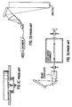
- FIGS. 1A and 1B show prior art grating based line narrowing configurations.
- FIG. 1C shows a pivotable grating structure
- FIGS. 2A, 2B and 2C demonstrate the functioning of a preferred embodiment of the present invention.
- FIG. 3 is a chart showing curvature as a function of rod turns.
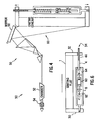
- FIG. 4 shows an excimer laser system using the present invention for bandwidth control.
- FIG. 5 is a perspective view of a preferred embodiment of the present invention.
- FIG. 6 shows a second preferred embodiment using magnets to provide compressive force.
- FIG. 2A shows a grating assembly having a bidirectional control unit attached to it but with no bending force applied to the grating. Shown are grating 1, left end plate 30, right end plate 32, compression spring housing 8, left compression spring 10, right compression spring 11, adjustment shaft 4 and piston 9 which is fixedly pinned to adjustment shaft 4. Adjustment shaft 4 comprises threaded length 4A (1/4-28 UNF-3B x 1.38 long) which mates with threaded channel in right end plate 32. In the FIG. 2A condition, both springs are applying equal compressive force which can offset each other or both springs may be unloaded.
- FIG. 3 shows the resulting curves of bend radius versus the number of turns of rod 4 with 28 threads per inch for springs rated at 52 pounds per inch and 108 pounds per inch. As shown in FIG. 3 operators are able with this design to make extremely fine adjustments to the curvature of the grating surface.
- FIG. 5 is a perspective view of a grating assembly 60 fabricated by Applicants and their co-workers.
- the assembly is comprised of grating 1, two grating end plates 2 (bonded to grating 1) right bi-directional bandwidth control end plate 5, lock nut 16, invar base plate 3 bonded to grating 1, alignment rod 4, socket 34, two linear bearings 12, compression spring housing 8, right compression spring 11, two thrust bearings 13, piston 9 pinned to rod 4, left compression spring 10, travel limiting piston 7 pinned to rod 4, radial ball bearing 14, pivot shaft 15 and left bandwidth control end plate 6.
- FIG. 4 shows a preferred embodiment of the present invention utilized to control bandwidth of an excimer laser system 50 comprising laser chamber 52, output coupler 54, prism beam expander 56 consisting of three prisms, pivotable tuning mirror 58 and grating assembly 60 which is the same as the assembly shown in FIGS. 1, 2A, 2B and 2C.
Landscapes
- Physics & Mathematics (AREA)
- Electromagnetism (AREA)
- Optics & Photonics (AREA)
- Engineering & Computer Science (AREA)
- Plasma & Fusion (AREA)
- General Physics & Mathematics (AREA)
- Lasers (AREA)
- Diffracting Gratings Or Hologram Optical Elements (AREA)
- Springs (AREA)
- Actuator (AREA)
Abstract
Description
Claims (8)
- A bi-directional bandwidth controlled grating assembly comprising:wherein said lined surface is made more concave or less convex by an action of screwing said adjustment rod in a direction to cause it to extend into said spring housing and said line surface is made more convex or less concave by an action of screwing said adjustment rod in a direction to cause it to withdraw from said spring housing.A) a grating defining a lined surface and a first end and a second end;B) a first end plate attached to said first end and extending in a direction away from said lined surface;C) a second end plate attached to said second end and extending in a direction away from said lined surface and having a threaded channel;D) a spring housing connected to said first end plate and defining a first pressure surface and a second pressure surface;E) an adjustment rod having a threaded section threaded into said threaded channel of said second end plate and extending into said spring housing;F) an adjustment rod piston fixed on said adjustment rod;G) a first compression element mounted between said first pressure surface and said adjustment rod piston;H) a second compression element mounted between said second pressure surface and said adjustment rod piston;
- An assembly as in Claim 1 wherein said first and second compression elements are springs.
- An assembly as in Claim 1 wherein said spring housing is pivotably attached to said first end plate.
- An assembly as in Claim 1 and also comprising at least two linear bearings for permitting said adjustment rod to extend substantially friction-free into said spring housing.
- An assembly as in Claim 1 and further comprising at least two thrust bearings mounted adjacent to said adjustment rod piston for permitting said adjustment rod to be rotated without causing substantial rotation of said first and second compression springs.
- An assembly as in Claim 1 wherein said first and second compression elements are comprised of two permanent magnets fixed to said spring housing and one permanent magnet fixed to said adjustment rod.
- An assembly as in Claim 1 wherein said assembly is installed in a line narrowing module mounted on a laser for line narrowing output beams of the laser.
- An assembly as in Claim 7 wherein said laser is an excimer laser.
Applications Claiming Priority (2)
| Application Number | Priority Date | Filing Date | Title |
|---|---|---|---|
| US09/248,466 US6094448A (en) | 1997-07-01 | 1999-02-11 | Grating assembly with bi-directional bandwidth control |
| US248466 | 1999-02-11 |
Publications (3)
| Publication Number | Publication Date |
|---|---|
| EP1028327A2 true EP1028327A2 (en) | 2000-08-16 |
| EP1028327A3 EP1028327A3 (en) | 2003-11-19 |
| EP1028327B1 EP1028327B1 (en) | 2006-01-25 |
Family
ID=22939261
Family Applications (1)
| Application Number | Title | Priority Date | Filing Date |
|---|---|---|---|
| EP00102801A Expired - Lifetime EP1028327B1 (en) | 1999-02-11 | 2000-02-10 | Grating assembly with bi-directional bandwidth control |
Country Status (5)
| Country | Link |
|---|---|
| US (1) | US6094448A (en) |
| EP (1) | EP1028327B1 (en) |
| JP (1) | JP3445215B2 (en) |
| KR (1) | KR100611942B1 (en) |
| DE (1) | DE60025658T2 (en) |
Families Citing this family (98)
| Publication number | Priority date | Publication date | Assignee | Title |
|---|---|---|---|---|
| US6721340B1 (en) * | 1997-07-22 | 2004-04-13 | Cymer, Inc. | Bandwidth control technique for a laser |
| US7006541B2 (en) * | 1998-06-01 | 2006-02-28 | Lambda Physik Ag | Absolute wavelength calibration of lithography laser using multiple element or tandem see through hollow cathode lamp |
| US6160832A (en) | 1998-06-01 | 2000-12-12 | Lambda Physik Gmbh | Method and apparatus for wavelength calibration |
| US6580517B2 (en) | 2000-03-01 | 2003-06-17 | Lambda Physik Ag | Absolute wavelength calibration of lithography laser using multiple element or tandem see through hollow cathode lamp |
| US6567450B2 (en) | 1999-12-10 | 2003-05-20 | Cymer, Inc. | Very narrow band, two chamber, high rep rate gas discharge laser system |
| US20020127497A1 (en) * | 1998-09-10 | 2002-09-12 | Brown Daniel J. W. | Large diffraction grating for gas discharge laser |
| US6700915B2 (en) | 1999-03-12 | 2004-03-02 | Lambda Physik Ag | Narrow band excimer laser with a resonator containing an optical element for making wavefront corrections |
| US6298080B1 (en) | 1999-03-12 | 2001-10-02 | Lambda Physik Ag | Narrow band excimer or molecular fluorine laser with adjustable bandwidth |
| US6801560B2 (en) * | 1999-05-10 | 2004-10-05 | Cymer, Inc. | Line selected F2 two chamber laser system |
| US6625191B2 (en) * | 1999-12-10 | 2003-09-23 | Cymer, Inc. | Very narrow band, two chamber, high rep rate gas discharge laser system |
| US6865210B2 (en) * | 2001-05-03 | 2005-03-08 | Cymer, Inc. | Timing control for two-chamber gas discharge laser system |
| US7856044B2 (en) | 1999-05-10 | 2010-12-21 | Cymer, Inc. | Extendable electrode for gas discharge laser |
| EP1240694B1 (en) * | 1999-12-22 | 2006-11-22 | Cymer, Inc. | Line narrowed laser with bidirection beam expansion |
| US7075963B2 (en) | 2000-01-27 | 2006-07-11 | Lambda Physik Ag | Tunable laser with stabilized grating |
| AU2001241421A1 (en) * | 2000-02-09 | 2001-08-20 | Cymer, Inc. | Bandwidth control technique for a laser |
| US6597462B2 (en) | 2000-03-01 | 2003-07-22 | Lambda Physik Ag | Laser wavelength and bandwidth monitor |
| US7180081B2 (en) * | 2000-06-09 | 2007-02-20 | Cymer, Inc. | Discharge produced plasma EUV light source |
| US6904073B2 (en) * | 2001-01-29 | 2005-06-07 | Cymer, Inc. | High power deep ultraviolet laser with long life optics |
| US6693939B2 (en) | 2001-01-29 | 2004-02-17 | Cymer, Inc. | Laser lithography light source with beam delivery |
| US6914919B2 (en) * | 2000-06-19 | 2005-07-05 | Cymer, Inc. | Six to ten KHz, or greater gas discharge laser system |
| US6603789B1 (en) | 2000-07-05 | 2003-08-05 | Lambda Physik Ag | Narrow band excimer or molecular fluorine laser with improved beam parameters |
| US6807205B1 (en) | 2000-07-14 | 2004-10-19 | Lambda Physik Ag | Precise monitor etalon calibration technique |
| US6801561B2 (en) | 2000-09-25 | 2004-10-05 | Lambda Physik Ag | Laser system and method for spectral narrowing through wavefront correction |
| US6747741B1 (en) | 2000-10-12 | 2004-06-08 | Lambda Physik Ag | Multiple-pass interferometric device |
| US6856638B2 (en) * | 2000-10-23 | 2005-02-15 | Lambda Physik Ag | Resonator arrangement for bandwidth control |
| US6421479B1 (en) | 2000-10-31 | 2002-07-16 | Zolo Technologies, Inc. | Apparatus and method facilitating optical alignment of a bulk optical multiplexer/demultiplexer |
| US6839372B2 (en) * | 2000-11-17 | 2005-01-04 | Cymer, Inc. | Gas discharge ultraviolet laser with enclosed beam path with added oxidizer |
| US6912052B2 (en) * | 2000-11-17 | 2005-06-28 | Cymer, Inc. | Gas discharge MOPA laser spectral analysis module |
| US7190707B2 (en) * | 2001-01-29 | 2007-03-13 | Cymer, Inc. | Gas discharge laser light source beam delivery unit |
| US6704340B2 (en) | 2001-01-29 | 2004-03-09 | Cymer, Inc. | Lithography laser system with in-place alignment tool |
| US20050025882A1 (en) * | 2001-01-29 | 2005-02-03 | Partlo William N. | Optical elements with protective undercoating |
| US6704339B2 (en) | 2001-01-29 | 2004-03-09 | Cymer, Inc. | Lithography laser with beam delivery and beam pointing control |
| US7039086B2 (en) * | 2001-04-09 | 2006-05-02 | Cymer, Inc. | Control system for a two chamber gas discharge laser |
| US6690704B2 (en) | 2001-04-09 | 2004-02-10 | Cymer, Inc. | Control system for a two chamber gas discharge laser |
| US7230964B2 (en) * | 2001-04-09 | 2007-06-12 | Cymer, Inc. | Lithography laser with beam delivery and beam pointing control |
| US7079564B2 (en) * | 2001-04-09 | 2006-07-18 | Cymer, Inc. | Control system for a two chamber gas discharge laser |
| US7009140B2 (en) * | 2001-04-18 | 2006-03-07 | Cymer, Inc. | Laser thin film poly-silicon annealing optical system |
| US7061959B2 (en) * | 2001-04-18 | 2006-06-13 | Tcz Gmbh | Laser thin film poly-silicon annealing system |
| US7167499B2 (en) * | 2001-04-18 | 2007-01-23 | Tcz Pte. Ltd. | Very high energy, high stability gas discharge laser surface treatment system |
| US7439530B2 (en) | 2005-06-29 | 2008-10-21 | Cymer, Inc. | LPP EUV light source drive laser system |
| US20050259709A1 (en) | 2002-05-07 | 2005-11-24 | Cymer, Inc. | Systems and methods for implementing an interaction between a laser shaped as a line beam and a film deposited on a substrate |
| US6928093B2 (en) * | 2002-05-07 | 2005-08-09 | Cymer, Inc. | Long delay and high TIS pulse stretcher |
| US7378673B2 (en) * | 2005-02-25 | 2008-05-27 | Cymer, Inc. | Source material dispenser for EUV light source |
| US7598509B2 (en) * | 2004-11-01 | 2009-10-06 | Cymer, Inc. | Laser produced plasma EUV light source |
| US7372056B2 (en) * | 2005-06-29 | 2008-05-13 | Cymer, Inc. | LPP EUV plasma source material target delivery system |
| US7465946B2 (en) * | 2004-03-10 | 2008-12-16 | Cymer, Inc. | Alternative fuels for EUV light source |
| US6760358B1 (en) | 2001-06-07 | 2004-07-06 | Lambda Physik Ag | Line-narrowing optics module having improved mechanical performance |
| US7088758B2 (en) | 2001-07-27 | 2006-08-08 | Cymer, Inc. | Relax gas discharge laser lithography light source |
| US7830934B2 (en) * | 2001-08-29 | 2010-11-09 | Cymer, Inc. | Multi-chamber gas discharge laser bandwidth control through discharge timing |
| US6963595B2 (en) | 2001-08-29 | 2005-11-08 | Cymer, Inc. | Automatic gas control system for a gas discharge laser |
| US20050100072A1 (en) * | 2001-11-14 | 2005-05-12 | Rao Rajasekhar M. | High power laser output beam energy density reduction |
| US7671349B2 (en) * | 2003-04-08 | 2010-03-02 | Cymer, Inc. | Laser produced plasma EUV light source |
| US6798812B2 (en) | 2002-01-23 | 2004-09-28 | Cymer, Inc. | Two chamber F2 laser system with F2 pressure based line selection |
| US7016388B2 (en) * | 2002-05-07 | 2006-03-21 | Cymer, Inc. | Laser lithography light source with beam delivery |
| US7741639B2 (en) * | 2003-01-31 | 2010-06-22 | Cymer, Inc. | Multi-chambered excimer or molecular fluorine gas discharge laser fluorine injection control |
| US7217941B2 (en) * | 2003-04-08 | 2007-05-15 | Cymer, Inc. | Systems and methods for deflecting plasma-generated ions to prevent the ions from reaching an internal component of an EUV light source |
| US7277188B2 (en) * | 2003-04-29 | 2007-10-02 | Cymer, Inc. | Systems and methods for implementing an interaction between a laser shaped as a line beam and a film deposited on a substrate |
| US7209507B2 (en) * | 2003-07-30 | 2007-04-24 | Cymer, Inc. | Method and apparatus for controlling the output of a gas discharge MOPA laser system |
| US6894785B2 (en) * | 2003-09-30 | 2005-05-17 | Cymer, Inc. | Gas discharge MOPA laser spectral analysis module |
| US6873418B1 (en) | 2003-09-30 | 2005-03-29 | Cymer, Inc. | Optical mountings for gas discharge MOPA laser spectral analysis module |
| US7277464B2 (en) * | 2003-12-18 | 2007-10-02 | Cymer, Inc. | Method and apparatus for controlling the output of a gas discharge laser system |
| US20060146906A1 (en) * | 2004-02-18 | 2006-07-06 | Cymer, Inc. | LLP EUV drive laser |
| US7196342B2 (en) * | 2004-03-10 | 2007-03-27 | Cymer, Inc. | Systems and methods for reducing the influence of plasma-generated debris on the internal components of an EUV light source |
| US7006547B2 (en) * | 2004-03-31 | 2006-02-28 | Cymer, Inc. | Very high repetition rate narrow band gas discharge laser system |
| US7522650B2 (en) * | 2004-03-31 | 2009-04-21 | Cymer, Inc. | Gas discharge laser chamber improvements |
| US20050286599A1 (en) * | 2004-06-29 | 2005-12-29 | Rafac Robert J | Method and apparatus for gas discharge laser output light coherency reduction |
| US7355191B2 (en) * | 2004-11-01 | 2008-04-08 | Cymer, Inc. | Systems and methods for cleaning a chamber window of an EUV light source |
| US7366219B2 (en) * | 2004-11-30 | 2008-04-29 | Cymer, Inc. | Line narrowing module |
| US20060114956A1 (en) * | 2004-11-30 | 2006-06-01 | Sandstrom Richard L | High power high pulse repetition rate gas discharge laser system bandwidth management |
| US7643522B2 (en) * | 2004-11-30 | 2010-01-05 | Cymer, Inc. | Method and apparatus for gas discharge laser bandwidth and center wavelength control |
| US7482609B2 (en) | 2005-02-28 | 2009-01-27 | Cymer, Inc. | LPP EUV light source drive laser system |
| US20060222034A1 (en) * | 2005-03-31 | 2006-10-05 | Cymer, Inc. | 6 Khz and above gas discharge laser system |
| US7633989B2 (en) * | 2005-06-27 | 2009-12-15 | Cymer, Inc. | High pulse repetition rate gas discharge laser |
| US7317536B2 (en) | 2005-06-27 | 2008-01-08 | Cymer, Inc. | Spectral bandwidth metrology for high repetition rate gas discharge lasers |
| US7365349B2 (en) | 2005-06-27 | 2008-04-29 | Cymer, Inc. | EUV light source collector lifetime improvements |
| US7141806B1 (en) | 2005-06-27 | 2006-11-28 | Cymer, Inc. | EUV light source collector erosion mitigation |
| US7180083B2 (en) | 2005-06-27 | 2007-02-20 | Cymer, Inc. | EUV light source collector erosion mitigation |
| JP4911558B2 (en) | 2005-06-29 | 2012-04-04 | 株式会社小松製作所 | Narrow band laser equipment |
| US8379687B2 (en) | 2005-06-30 | 2013-02-19 | Cymer, Inc. | Gas discharge laser line narrowing module |
| US7653095B2 (en) * | 2005-06-30 | 2010-01-26 | Cymer, Inc. | Active bandwidth control for a laser |
| US7394083B2 (en) | 2005-07-08 | 2008-07-01 | Cymer, Inc. | Systems and methods for EUV light source metrology |
| US7679029B2 (en) | 2005-10-28 | 2010-03-16 | Cymer, Inc. | Systems and methods to shape laser light as a line beam for interaction with a substrate having surface variations |
| US7317179B2 (en) | 2005-10-28 | 2008-01-08 | Cymer, Inc. | Systems and methods to shape laser light as a homogeneous line beam for interaction with a film deposited on a substrate |
| US7471455B2 (en) | 2005-10-28 | 2008-12-30 | Cymer, Inc. | Systems and methods for generating laser light shaped as a line beam |
| US7321607B2 (en) * | 2005-11-01 | 2008-01-22 | Cymer, Inc. | External optics and chamber support system |
| US7453077B2 (en) | 2005-11-05 | 2008-11-18 | Cymer, Inc. | EUV light source |
| US7307237B2 (en) * | 2005-12-29 | 2007-12-11 | Honeywell International, Inc. | Hand-held laser welding wand nozzle assembly including laser and feeder extension tips |
| US8259764B2 (en) * | 2006-06-21 | 2012-09-04 | Cymer, Inc. | Bandwidth control device |
| JP5157004B2 (en) | 2006-07-04 | 2013-03-06 | 株式会社小松製作所 | Method for adjusting spectral width of narrow-band laser |
| US9018561B2 (en) | 2007-05-23 | 2015-04-28 | Cymer, Llc | High power seed/amplifier laser system with beam shaping intermediate the seed and amplifier |
| US7655925B2 (en) * | 2007-08-31 | 2010-02-02 | Cymer, Inc. | Gas management system for a laser-produced-plasma EUV light source |
| US7812329B2 (en) * | 2007-12-14 | 2010-10-12 | Cymer, Inc. | System managing gas flow between chambers of an extreme ultraviolet (EUV) photolithography apparatus |
| US8519366B2 (en) * | 2008-08-06 | 2013-08-27 | Cymer, Inc. | Debris protection system having a magnetic field for an EUV light source |
| US7756171B2 (en) * | 2008-10-21 | 2010-07-13 | Cymer, Inc. | Method and apparatus for laser control in a two chamber gas discharge laser |
| US7720120B2 (en) * | 2008-10-21 | 2010-05-18 | Cymer, Inc. | Method and apparatus for laser control in a two chamber gas discharge laser |
| US7751453B2 (en) * | 2008-10-21 | 2010-07-06 | Cymer, Inc. | Method and apparatus for laser control in a two chamber gas discharge laser |
| US8144739B2 (en) * | 2008-10-24 | 2012-03-27 | Cymer, Inc. | System method and apparatus for selecting and controlling light source bandwidth |
| JP5687488B2 (en) | 2010-02-22 | 2015-03-18 | ギガフォトン株式会社 | Extreme ultraviolet light generator |
Family Cites Families (21)
| Publication number | Priority date | Publication date | Assignee | Title |
|---|---|---|---|---|
| US3229951A (en) * | 1960-12-07 | 1966-01-18 | North American Aviation Inc | Resilient mounting system |
| US3443243A (en) * | 1965-06-23 | 1969-05-06 | Bell Telephone Labor Inc | Frequency selective laser |
| US4360925A (en) * | 1980-02-25 | 1982-11-23 | Quanta Ray, Inc. | Laser employing an unstable resonator having an output transmissive mirror |
| US4803696A (en) * | 1987-06-30 | 1989-02-07 | Hughes Aircraft Company | Laser with grating feedback unstable resonator |
| DE3730975A1 (en) * | 1987-09-15 | 1989-03-23 | Siemens Ag | MAGNETIC SPRING AND METHOD FOR ADJUSTMENT |
| JPH03505652A (en) * | 1988-04-22 | 1991-12-05 | フラウンホッファー―ゲゼルシャフト ツァ フェルダールング デァ アンゲヴァンテン フォアシュンク エー.ファオ. | laser resonator |
| JP2531788B2 (en) * | 1989-05-18 | 1996-09-04 | 株式会社小松製作所 | Narrowband oscillation excimer laser |
| US5150370A (en) * | 1989-06-14 | 1992-09-22 | Matsushita Electric Industrial Co., Ltd. | Narrow-band laser apparatus |
| US5095492A (en) * | 1990-07-17 | 1992-03-10 | Cymer Laser Technologies | Spectral narrowing technique |
| US5012483A (en) * | 1990-09-27 | 1991-04-30 | The United States Of America As Represented By The Secretary Of The Navy | Narrow-bandwidth diffraction-limited coupled stable-unstable resonator laser cavity |
| US5043998A (en) * | 1990-10-16 | 1991-08-27 | United States Of America As Represented By The Secretary Of The Navy | Narrow-bandwidth unstable resonator laser cavity |
| EP0509903B1 (en) * | 1991-04-15 | 1996-09-18 | Kabushiki Kaisha TOPCON | Process and apparatus for measuring axial eye length |
| US5216680A (en) * | 1991-07-11 | 1993-06-01 | Board Of Regents, The University Of Texas System | Optical guided-mode resonance filter |
| US5559816A (en) * | 1994-10-26 | 1996-09-24 | Lambda Physik Gesellschaft Zur Herstellung Von Lasern Mbh | Narrow-band laser apparatus |
| US5775469A (en) * | 1996-04-15 | 1998-07-07 | Kang; Song D. | Electrodynamic strut with associated bracing mechanism |
| US5767965A (en) * | 1996-05-31 | 1998-06-16 | Instruments S.A., Inc. | Apparatus and method for driving diffraction gratings |
| US5852627A (en) * | 1997-09-10 | 1998-12-22 | Cymer, Inc. | Laser with line narrowing output coupler |
| JPH10341057A (en) * | 1997-06-06 | 1998-12-22 | Ando Electric Co Ltd | External resonator type wavelength-variable semiconductor laser optical source and wavelength variable method therefor |
| EP0992092B1 (en) * | 1997-07-01 | 2003-04-23 | Cymer, Inc. | Very narrow band laser with unstable resonance cavity |
| US5999671A (en) * | 1997-10-27 | 1999-12-07 | Lucent Technologies Inc. | Tunable long-period optical grating device and optical systems employing same |
| JPH11307864A (en) * | 1998-04-23 | 1999-11-05 | Ando Electric Co Ltd | External resonator variable wavelength light source |
-
1999
- 1999-02-11 US US09/248,466 patent/US6094448A/en not_active Expired - Lifetime
-
2000
- 2000-02-10 EP EP00102801A patent/EP1028327B1/en not_active Expired - Lifetime
- 2000-02-10 KR KR1020000006152A patent/KR100611942B1/en not_active Expired - Lifetime
- 2000-02-10 DE DE60025658T patent/DE60025658T2/en not_active Expired - Lifetime
- 2000-02-14 JP JP2000077241A patent/JP3445215B2/en not_active Expired - Lifetime
Also Published As
| Publication number | Publication date |
|---|---|
| JP3445215B2 (en) | 2003-09-08 |
| JP2000312048A (en) | 2000-11-07 |
| DE60025658D1 (en) | 2006-04-13 |
| DE60025658T2 (en) | 2006-07-20 |
| KR100611942B1 (en) | 2006-08-11 |
| EP1028327A3 (en) | 2003-11-19 |
| EP1028327B1 (en) | 2006-01-25 |
| US6094448A (en) | 2000-07-25 |
| KR20000057994A (en) | 2000-09-25 |
Similar Documents
| Publication | Publication Date | Title |
|---|---|---|
| US6094448A (en) | Grating assembly with bi-directional bandwidth control | |
| USRE45249E1 (en) | System method and apparatus for selecting and controlling light source bandwidth | |
| JP3842541B2 (en) | Narrow band laser with precise wavelength control | |
| EP1330859A1 (en) | Smart laser with fast deformable grating | |
| JP2004507784A (en) | Adjustable light filters | |
| US6498803B2 (en) | Narrow band excimer or molecular fluorine laser with adjustable bandwidth | |
| US20030227560A1 (en) | Digital camera system with piezoelectric actuators | |
| US4442524A (en) | Multiple lever apparatus for positioning an optical element | |
| US20110122901A1 (en) | High power high pulse repetition rate gas discharge laser system | |
| EP1028502A2 (en) | Smart laser with automated beam quality control | |
| WO2003105459A2 (en) | Digital camera system with piezoelectric actuators | |
| KR20160145126A (en) | Integral preload mechanism for piezoelectric actuator | |
| US7653094B2 (en) | External cavity laser with flexure tuning element | |
| US4723841A (en) | Variable transmission output coupler and deviationless tuner for tunable lasers | |
| JP2003215420A (en) | Lens inclination adjusting mechanism and lens barrel | |
| JP4452442B2 (en) | Tunable optical filter | |
| JP5048939B2 (en) | Etalon device and its assembly adjustment method | |
| US20030072347A1 (en) | Apparatus for locking bending mechanism that bends reflex type wavelength selection element | |
| JPH1126856A (en) | Bending mechanism of reflective wavelength selective element | |
| JPH0547482Y2 (en) | ||
| RU2065650C1 (en) | Output window | |
| KR100316654B1 (en) | Lens Position Adjuster of Optical System_ | |
| JP2723018B2 (en) | Driving device for parabolic antenna with auxiliary driving mechanism | |
| JP2003167179A (en) | Positioning and fixing apparatus | |
| JP2003107371A (en) | Variable type optical attenuator actuator |
Legal Events
| Date | Code | Title | Description |
|---|---|---|---|
| PUAI | Public reference made under article 153(3) epc to a published international application that has entered the european phase |
Free format text: ORIGINAL CODE: 0009012 |
|
| 17P | Request for examination filed |
Effective date: 20000413 |
|
| AK | Designated contracting states |
Kind code of ref document: A2 Designated state(s): AT BE CH CY DE DK ES FI FR GB GR IE IT LI LU MC NL PT SE |
|
| AX | Request for extension of the european patent |
Free format text: AL;LT;LV;MK;RO;SI |
|
| PUAL | Search report despatched |
Free format text: ORIGINAL CODE: 0009013 |
|
| AK | Designated contracting states |
Kind code of ref document: A3 Designated state(s): AT BE CH CY DE DK ES FI FR GB GR IE IT LI LU MC NL PT SE |
|
| AX | Request for extension of the european patent |
Extension state: AL LT LV MK RO SI |
|
| RAP1 | Party data changed (applicant data changed or rights of an application transferred) |
Owner name: CYMER, INC. |
|
| 17Q | First examination report despatched |
Effective date: 20040408 |
|
| AKX | Designation fees paid |
Designated state(s): DE GB NL |
|
| GRAP | Despatch of communication of intention to grant a patent |
Free format text: ORIGINAL CODE: EPIDOSNIGR1 |
|
| GRAS | Grant fee paid |
Free format text: ORIGINAL CODE: EPIDOSNIGR3 |
|
| GRAA | (expected) grant |
Free format text: ORIGINAL CODE: 0009210 |
|
| AK | Designated contracting states |
Kind code of ref document: B1 Designated state(s): DE GB NL |
|
| REG | Reference to a national code |
Ref country code: GB Ref legal event code: FG4D |
|
| REF | Corresponds to: |
Ref document number: 60025658 Country of ref document: DE Date of ref document: 20060413 Kind code of ref document: P |
|
| PG25 | Lapsed in a contracting state [announced via postgrant information from national office to epo] |
Ref country code: GB Free format text: LAPSE BECAUSE OF NON-PAYMENT OF DUE FEES Effective date: 20060425 |
|
| PLBE | No opposition filed within time limit |
Free format text: ORIGINAL CODE: 0009261 |
|
| STAA | Information on the status of an ep patent application or granted ep patent |
Free format text: STATUS: NO OPPOSITION FILED WITHIN TIME LIMIT |
|
| GBPC | Gb: european patent ceased through non-payment of renewal fee |
Effective date: 20060425 |
|
| 26N | No opposition filed |
Effective date: 20061026 |
|
| REG | Reference to a national code |
Ref country code: DE Ref legal event code: R082 Ref document number: 60025658 Country of ref document: DE Representative=s name: GRUENECKER PATENT- UND RECHTSANWAELTE PARTG MB, DE Ref country code: DE Ref legal event code: R081 Ref document number: 60025658 Country of ref document: DE Owner name: CYMER, LLC (N.D.GES. D.STAATES NEVADA), SAN DI, US Free format text: FORMER OWNER: CYMER, INC., SAN DIEGO, CALIF., US |
|
| REG | Reference to a national code |
Ref country code: NL Ref legal event code: HC Owner name: CYMER LLC; US Free format text: DETAILS ASSIGNMENT: VERANDERING VAN EIGENAAR(S), VERANDERING VAN NAAM VAN DE EIGENAAR(S); FORMER OWNER NAME: KONA TECHNOLOGIES LLC Effective date: 20160930 Ref country code: NL Ref legal event code: PD Owner name: KONA TECHNOLOGIES LLC; US Free format text: DETAILS ASSIGNMENT: VERANDERING VAN EIGENAAR(S), SAMENVOEGEN; FORMER OWNER NAME: CYMER, INC. Effective date: 20160930 |
|
| PGFP | Annual fee paid to national office [announced via postgrant information from national office to epo] |
Ref country code: NL Payment date: 20180216 Year of fee payment: 19 |
|
| PGFP | Annual fee paid to national office [announced via postgrant information from national office to epo] |
Ref country code: DE Payment date: 20180219 Year of fee payment: 19 |
|
| REG | Reference to a national code |
Ref country code: DE Ref legal event code: R119 Ref document number: 60025658 Country of ref document: DE |
|
| REG | Reference to a national code |
Ref country code: NL Ref legal event code: MM Effective date: 20190301 |
|
| PG25 | Lapsed in a contracting state [announced via postgrant information from national office to epo] |
Ref country code: DE Free format text: LAPSE BECAUSE OF NON-PAYMENT OF DUE FEES Effective date: 20190903 Ref country code: NL Free format text: LAPSE BECAUSE OF NON-PAYMENT OF DUE FEES Effective date: 20190301 |