EP1027849A2 - Beverage container with cap and spout - Google Patents
Beverage container with cap and spout Download PDFInfo
- Publication number
- EP1027849A2 EP1027849A2 EP00300929A EP00300929A EP1027849A2 EP 1027849 A2 EP1027849 A2 EP 1027849A2 EP 00300929 A EP00300929 A EP 00300929A EP 00300929 A EP00300929 A EP 00300929A EP 1027849 A2 EP1027849 A2 EP 1027849A2
- Authority
- EP
- European Patent Office
- Prior art keywords
- spout
- cap
- base
- rim
- beverage container
- Prior art date
- Legal status (The legal status is an assumption and is not a legal conclusion. Google has not performed a legal analysis and makes no representation as to the accuracy of the status listed.)
- Withdrawn
Links
Images

Classifications
-
- B—PERFORMING OPERATIONS; TRANSPORTING
- B65—CONVEYING; PACKING; STORING; HANDLING THIN OR FILAMENTARY MATERIAL
- B65D—CONTAINERS FOR STORAGE OR TRANSPORT OF ARTICLES OR MATERIALS, e.g. BAGS, BARRELS, BOTTLES, BOXES, CANS, CARTONS, CRATES, DRUMS, JARS, TANKS, HOPPERS, FORWARDING CONTAINERS; ACCESSORIES, CLOSURES, OR FITTINGS THEREFOR; PACKAGING ELEMENTS; PACKAGES
- B65D47/00—Closures with filling and discharging, or with discharging, devices
-
- B—PERFORMING OPERATIONS; TRANSPORTING
- B65—CONVEYING; PACKING; STORING; HANDLING THIN OR FILAMENTARY MATERIAL
- B65D—CONTAINERS FOR STORAGE OR TRANSPORT OF ARTICLES OR MATERIALS, e.g. BAGS, BARRELS, BOTTLES, BOXES, CANS, CARTONS, CRATES, DRUMS, JARS, TANKS, HOPPERS, FORWARDING CONTAINERS; ACCESSORIES, CLOSURES, OR FITTINGS THEREFOR; PACKAGING ELEMENTS; PACKAGES
- B65D51/00—Closures not otherwise provided for
- B65D51/16—Closures not otherwise provided for with means for venting air or gas
- B65D51/1672—Closures not otherwise provided for with means for venting air or gas whereby venting occurs by manual actuation of the closure or other element
- B65D51/1688—Venting occurring during initial closing or opening of the container, by means of a passage for the escape of gas between the closure and the lip of the container mouth, e.g. interrupted threads
-
- B—PERFORMING OPERATIONS; TRANSPORTING
- B65—CONVEYING; PACKING; STORING; HANDLING THIN OR FILAMENTARY MATERIAL
- B65D—CONTAINERS FOR STORAGE OR TRANSPORT OF ARTICLES OR MATERIALS, e.g. BAGS, BARRELS, BOTTLES, BOXES, CANS, CARTONS, CRATES, DRUMS, JARS, TANKS, HOPPERS, FORWARDING CONTAINERS; ACCESSORIES, CLOSURES, OR FITTINGS THEREFOR; PACKAGING ELEMENTS; PACKAGES
- B65D25/00—Details of other kinds or types of rigid or semi-rigid containers
- B65D25/38—Devices for discharging contents
- B65D25/40—Nozzles or spouts
- B65D25/48—Separable nozzles or spouts
Abstract
Description
- The present invention relates in general to beverage containers for personal use. In particular, the present invention relates to a beverage container which may be used for storing and dispensing a single serving of carbonated and non-carbonated beverages.
- In the home, beverages are often transferred from original packaging to a container for personal use. Such containers are currently available in a variety of forms. In the general sense, these containers consist of a base defining a cavity for retaining the beverage and a cap for sealing the base. For storing non-carbonated beverages, the seal between the base and cap is often of primary concern, as leakage poses the obvious problems of beverage loss, beverage contamination, and mess. The seal is also important for the storage of carbonated beverages for the same reasons. Further the seal must additionally be to some degree gas-tight to retain the carbonation for the desired period of time.
- While the seal is thus also important for carbonated beverage containers, a greater concern is typically the danger posed by the build-up of pressure within the container, especially during removal of the cap. Specifically, the internal pressure acts upon the underside of the cap tending to force it away from the base. As the user removes the cap, this pressure may cause the cap to be expelled from the container in a very energetic manner. This may even be so energetic as to cause danger to the user.
- According to the invention, there is provided a beverage container with cap and spout, having a base with a bottom wall, side wall extending upward therefrom to an upper rim, and threads formed on the exterior thereof, a cap having a central portion, a shoulder section and skirt having inner threads thereon for mating with said threads on said base, characterised by
- a spout selectively mountable to said base in a specific angular orientation with respect to said threads, said spout including a main panel having an aperture, a spout skirt extending downward from said main panel for engagement with said side wall adjacent said upper rim, and a follower ridge extending upward from said main panel,
- said shoulder section including a cam surface in the form of a downward facing shoulder having a first end and a second end, said cam surface sloping downward from said first end to said second end at an angle substantially equal to that of said threads, such that said cam surface will slide upon said follower ridge during at least a portion of the rotation of said cap as it is applied and removed, and said cam surface will therefore retain said spout in position as said cap moves upward relative to said base.
-
- The preferred embodiment of the invention will store a beverage with freshness for a predetermined desired amount of time, and has a sufficient seal for use with both carbonated and non-carbonated beverages.
- The preferred embodiment of the invention automatically vents internal pressure during opening.
- In this preferred embodiment, the container has a simple design using only a few parts which may each be easily mass-produced.
- The provision, on the shoulder section of the spout contact section having the cam surface, in conjunction with the follower ridge on the spout which is engaged by the cam surface, serves to retain the spout in position as the cap is rotated for removal. This permits the spout to vent any accumulated pressure from a stored carbonated beverage, and thus prevents the spout from being disengaged from the base due to the accumulated pressure.
- An embodiment of the invention is described below by way of example with reference to the accompanying drawings, in which like reference numerals denote like elements and in which:-
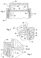
- Fig. 1 is an exploded perspective view of a container according to the present invention showing the base, spout and cap;
- Fig. 2 is a detail cross-sectional view of the assembled base and cap of the container of Fig. 1;
- Fig. 3 is a cross-sectional view showing a detail of Fig. 2;
- Fig. 4 is a cross-sectional view showing a second detail of Fig. 2;
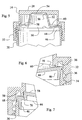
- Fig. 5 is a detail cross-sectional view of the assembled base, spout and cap of the container of Fig. 1;
- Fig. 6 is a cross-sectional view showing a detail of Fig. 5; and
- Fig. 7 is a cross-sectional view showing a second detail of Fig. 5.
-
- With reference to Fig. 1, a container according to the present invention is generally designated by
reference numeral 10. Thecontainer 10 includes at least abase 12 and acap 14, and may further include aspout 16. In particular, when used to store non-carbonated beverages, thebase 12 andcap 14 may be used alone (but may also be used with the spout 16). However, when used to store carbonated beverages, thebase 12 andcap 14 will be used with thespout 16. - The
base 12 includes abottom wall 18 having a periphery, and aside wall 20 extending upward from this periphery, and ending at anupper rim 22. While the periphery of thebottom wall 18 may have various shapes, theupper rim 22 will be circular. Thebottom wall 18 andside wall 20 together define acontainer interior 24 which may receive the beverage to be stored. Theupper rim 22 further defines amouth 26 providing access to, and egress from, this interior. Thebottom wall 18 andside wall 20 may be formed of various materials such as glass, metal or plastic, and may be of the same or diverse materials. It is preferred, however, that they be formed as a monolithic plastic unit formed by injection molding. This is due not only to reduced cost, but also to permit sufficient deformation of the upper rim 22 (described more fully below) which may be difficult to achieve using more rigid materials such as glass or metal. - As noted, a beverage may be stored within the
interior 24 ofbase 12. To prevent unintended egress of the beverage, thecap 14 is provided and serves to close theinterior 24. As best illustrated in Fig. 2, thecap 14 includes acentral portion 28 having generally domed shape with a lower edge, ashoulder section 30 at this lower edge, and askirt 32 extending downward from theshoulder section 30. Theskirt 32 generally has an inner diameter slightly greater than the outer diameter of thebase 12, andthreads 34 are formed on thebase 12 to mate withinner threads 36 on the interior ofskirt 32. Thethreads 34 andinner threads 36 permit thecap 14 to be secured to thebase 12 by threaded engagement. When fully seated, theshoulder section 30 will abut against theupper rim 22, either directly as show in Figs. 2-4, or via the spout as shown in Figs. 5-7. - As best illustrated in Figs. 3 and 4, the
shoulder section 30 is comprised of two distinct sections. These are arim contact section 38 and spout contact section 40 (described more fully below). Therim contact section 38 is intended to abut directly against theupper rim 22 when thecap 14 is fully seated uponbase 12. As may be envisioned, this will serve to block the flow of the beverage from theinterior 24. In practice, however, it can be difficult to achieve proper contact, and thus a proper seal, about the entirety ofupper rim 22. - To ensure a proper seal, it is preferred that the
base 12 include a sealing bead 42 (Fig. 1) extending about the exterior ofside wall 20 at a position in proximity to, but spaced from, theupper rim 22. Further, it is preferred that the interior ofskirt 32 taper inward adjacent theshoulder section 30, and in particular betweenshoulder section 30 and the position of thesealing bead 42 when thecap 14 is fully seated. As may be seen, the inward taper will serve to compress upon thesealing bead 42 as thecap 14 moves toward the seated position, providing the desired seal should theupper rim 22 not fully abutrim contact section 38. - The above description should make clear the operation of the
container 10 when used with only thebase 12 andcap 14. As noted, this use is suitable for non-carbonated beverages. For carbonated beverages, it is preferred (but not required) that thespout 16 also be used. This arrangement will now be discussed. - As shown in Fig. 1, the
spout 16 generally includes amain panel 44 which extends across themouth 26 and has an outer periphery which may rest upon theupper rim 22. Spaced inward from this outer periphery and extending downward is aspout skirt 46 sized to engage theupper rim 22, preferably at the inner face of theside wall 20. In the preferred embodiment shown, the inner face of theside wall 20 includes acircumferential recess 48 which mates with thespout skirt 46. Therecess 48 reduces the thickness of theside wall 20 permitting it to more easily expand to receive thespout skirt 46 in a close fit to prevent egress of the beverage. This mating relationship may include an outward taper toward the free edge of thespout skirt 46 as shown. - Extending through the
main panel 44 is anaperture 50 through which the beverage will be dispensed. In the preferred embodiment shown, aneck extension 52 having the shape of frustum of a conical tube extends from thisaperture 50 to aneck rim 54. Thisneck extension 52 will preferably have a size approximating the opening of standard carbonated beverage bottles for easy and familiar use in drinking from theneck extension 52. When thecap 14 is fully seated upon thebase 12, thecentral portion 28 will seal theaperture 50. When thepreferred neck extension 52 is employed, thecentral portion 28 will abut against theneck rim 54. It is noted that thecap 14 is rotated about its longitudinal axis during this seating to thebase 12, and for this reason it is preferred (but not required) that theneck extension 52 be coaxial with the longitudinal axis of thecap 14. To ensure a proper seal, the inner face of thecentral portion 28 may include anabutment surface 56 shaped to mate with theneck rim 54 when thecap 14 is seated. - The above elements are all that are strictly required to employ the
spout 16. However, this arrangement provides only the benefit of the reduceddiameter neck extension 52 for drinking, and no benefits relating to use with carbonated beverages. For these additional benefits, additional structure is required. - Specifically, the
spout 16 preferably also includes at least onefollower ridge 58 rising above themain panel 44 at a position underlying thespout contact section 40 ofshoulder section 30. In the preferred embodiment threesuch follower ridges 58 are employed at equal angular spacings, and each extends radially outward from theneck extension 52. During the final portion of rotation to mount thecap 14, and conversely the initial portion of rotation to remove thecap 14, the (or each)follower ridge 58 will contact acam surface 60 formed on thespout contact section 40 of shoulder section 30 (thecam surface 60 being best illustrated in Fig. 2). This contact will ensure that thespout 16 does not move from its position mounted upon thebase 12. - The reason for this is the internal pressure developed by carbonated beverages. During the time when the
cap 14 is removed, this pressure is easily released to atmosphere through theaperture 50. However, during the period when thecap 14 is seated, the interior 24 is sealed by thespout skirt 46 and the abutment of thecentral portion 28 against theneck rim 54. This sealed condition will permit this pressure to accumulate. As thecap 14 is later removed, it moves upward and away from thebase 12, and away from engagement withneck rim 54. This accumulated pressure, however, will tend to force thespout 16 upward against thecap 14. The pressure can often be sufficient that thespout 16 will actually travel upward with thecap 14 until thespout skirt 46 is disengaged from thebase 12. If this occurs near the point where thethreads 34 andinner threads 36 disengage, the pressure can cause thecap 14 withspout 16 to be propelled energetically upward and away from thebase 12. This represents a danger to the user. - To prevent this, the
container 10 will vent the interior 24 well prior to disengagement of thethreads 34 andinner threads 36. This is achieved through the use of thefollower ridge 58 andcam surface 60. Specifically, thecam surface 60 has the general form of a downward directed shoulder having a first end 62 (Fig. 2) which angles downward toward asecond end 64. This angle is substantially equal to that of thethreads 34 andinner threads 36. The length of thecam surface 60 will of course be no greater than the circumference at thespout contact section 40, and in the preferred embodiment shown encompasses 120° (there being threecam surfaces 60, one for each of the three follower ridges 58). - The operation of theses elements is as follows. When the
cap 14 is fully seated, thecam surface 60 is contacting thefollower ridge 58, preventing upward movement, and thecap 14 is oriented with thefirst end 62 ofcam surface 60 close to thefollower ridge 58. As the user begins rotation of thecap 14 for removal, the cap rotates with respect to thebase 12, and also moves away from thebase 12. During this initial rotation, thecam surface 60 slides over thefollower ridge 58, with th point of contact maintaining a constant distance from thebase 12 and thus retaining thefollower ridge 58 in position against upward movement with the cap. As such, the cap is moving upward with respect to thebase 12 andspout 16, but thespout 16 is not moving upward. This movement of the cap will then cause theabutment surface 56 to move away from the neck rim 54 in the upward direction. This of course breaks the seal between these elements, and the internal pressure is vented through the neck rim 54 into the interior of thecap 14, and via the threaded engagement of thecap 14, to the atmosphere. As such, it is seen that the movement of thecap 14 restrains upward movement of thespout 16, and permits venting of the container. - The above description of operation relies upon the
follower ridge 58 being in the proper position (i.e., adjacent thefirst end 62 of cam surface 60) when thecap 14 is seated. To ensure this, the angular orientation, i.e., clocking, of thespout 16 with respect to thethreads 34 is critical. As best illustrated in Fig. 1, this clocking is achieved by forming a unique mating relationship between the base 12 andspout 16. In particular, theupper rim 22 includes apositioning recess 66 for eachfollower ridge 58 employed, and thespout 16 includes a like number ofpositioning projections 68 extending radially outward from thespout skirt 46. This requires that thespout 16 be placed in the proper position upon thebase 12 for operation of thecam surface 60. It is noted also that the sealingbead 42 is located below thepositioning recess 66, so that thepositioning recess 66 does not break the seal formed by the sealingbead 42. - While the above description is sufficient, in the seated condition of
cap 14 thecam surface 60 will abut against thefollower ridge 58. This small contact area may lead to failure of the material at thefollower ridge 58 before the desired product life. To reduce this problem, and thus extend product life, thespout contact section 40 may additionally include acontact ridge 70 located radially outward ofcam surface 60, and having a lower edge within a plane perpendicular to the longitudinal axis. This lower edge is located at a position to engage with themain panel 44 when thecap 14 is fully seated, as shown in Fig. 6. As may be envisioned, however, as thecap 14 rotates for removal, thecontact ridge 70 will move away from themain panel 44 due to the upward movement of the cap. As such, thecontact ridge 70 is effective only when thecap 14 is seated. - From the above description it may be seen that the
container 10 will provide a beverage container having a relatively small opening in the spout for ease of drinking, but which permits removal of the spout for easy filling of the container. Further, the container may be employed to safely hold a carbonated beverage by virtue of its venting action upon opening. Beyond this,container 10 may be used without thespout 16 in a conventional manner to hold non-carbonated beverages. In both uses thecontainer 10 provides the proper seals to prevent unintended egress of the beverage due to the unique structure of theshoulder section 30. - From the foregoing it will be seen that this invention is one well adapted to attain all ends and objects hereinabove set forth together with the other advantages which are obvious and which are inherent to the structure.
- It will be understood that certain features and subcombinations are of utility and may be employed without reference to other features and subcombinations. This is contemplated by and is within the scope of the claims.
- Since many possible embodiments may be made of the invention without departing from the scope thereof, it is to be understood that all matter herein set forth or shown in the accompanying drawings is to be interpreted as illustrative, and not in a limiting sense.
- The features disclosed in the foregoing description, in the following claims and/or in he accompanying drawings may, both separately and in any combination hereof, be material for realising the invention in diverse forms thereof.
Claims (7)
- A beverage container with cap and spout, having a base with a bottom wall, side wall extending upward therefrom to an upper rim, and threads formed on the exterior thereof, a cap having a central portion, a shoulder section and skirt having inner threads thereon for mating with said threads on said base, characterized bya spout selectively mountable to said base in a specific angular orientation with respect to said threads, said spout including a main panel having an aperture, a spout skirt extending downward from said main panel for engagement with said side wall adjacent said upper rim, and a follower ridge extending upward from said main panel,said shoulder section including a cam surface in the form of a downward facing shoulder having a first end and a second end, said cam surface sloping downward from said first end to said second end at an angle substantially equal to that of said threads, such that said cam surface will slide upon said follower ridge during at least a portion of the rotation of said cap as it is applied and removed, and said cam surface will therefore retain said spout in position as said cap moves upward relative to said base.
- A beverage container with cap and spout as in claim 1, wherein said shoulder section further includes a rim contact section which will seal against said upper rim when said spout is not positioned upon said base.
- A beverage container with cap and spout as in claim 1, wherein said specific angular orientation is achieved by a positioning recess extending into said upper rim, and a mating positioning projection extending from said spout skirt.
- A beverage container with cap and spout as in claim 1, wherein said spout farther includes a neck extension extending upward from said aperture, and ending at a neck rim, said central portion of said cap sealing against said neck rim when said cap is fully seated upon said base.
- A beverage container with cap and spout as in claim 4, wherein said shoulder section further includes a rim contact section which will seal against said upper rim when said spout is not positioned upon said base.
- A beverage container with cap and spout as in claim 5, wherein said spout skirt is received within said upper rim, and said specific angular orientation is achieved by a positioning recess extending into said upper rim, and a mating positioning projection extending from said spout skirt.
- A beverage container with cap and spout as in claim 6, wherein said neck extension is coaxial with a longitudinal axis of said cap, and an inner surface of said central portion includes an abutment surface against which said neck rim seals when said cap is seated.
Applications Claiming Priority (2)
| Application Number | Priority Date | Filing Date | Title |
|---|---|---|---|
| US09/248,240 US6041982A (en) | 1999-02-10 | 1999-02-10 | Beverage container with cap and spout |
| US248240 | 1999-02-10 |
Publications (2)
| Publication Number | Publication Date |
|---|---|
| EP1027849A2 true EP1027849A2 (en) | 2000-08-16 |
| EP1027849A3 EP1027849A3 (en) | 2005-02-02 |
Family
ID=22938261
Family Applications (1)
| Application Number | Title | Priority Date | Filing Date |
|---|---|---|---|
| EP00300929A Withdrawn EP1027849A3 (en) | 1999-02-10 | 2000-02-07 | Beverage container with cap and spout |
Country Status (15)
| Country | Link |
|---|---|
| US (1) | US6041982A (en) |
| EP (1) | EP1027849A3 (en) |
| JP (1) | JP3459391B2 (en) |
| KR (1) | KR100393154B1 (en) |
| CN (1) | CN1103720C (en) |
| AR (1) | AR022489A1 (en) |
| BR (1) | BR0000337A (en) |
| CA (1) | CA2297521A1 (en) |
| CZ (1) | CZ2000468A3 (en) |
| HK (1) | HK1029972A1 (en) |
| HR (1) | HRP20000072A2 (en) |
| HU (1) | HUP0000560A3 (en) |
| IL (1) | IL134331A (en) |
| PL (1) | PL338326A1 (en) |
| ZA (1) | ZA200000546B (en) |
Families Citing this family (39)
| Publication number | Priority date | Publication date | Assignee | Title |
|---|---|---|---|---|
| US20040173556A1 (en) * | 1997-09-19 | 2004-09-09 | Smolko Daniel D. | Vented closures for containers |
| US7107783B2 (en) * | 1997-09-19 | 2006-09-19 | Advanced Porcus Technologies, Llc | Self-cooling containers for liquids |
| US6398048B1 (en) * | 1997-09-19 | 2002-06-04 | Gregory Kevorkian | Vented beverage container |
| CA2305041A1 (en) | 2000-04-13 | 2001-10-13 | Pierre Tardif | Reusable pouring cap for a container capable of receiving potable liquids for human consumption |
| DE60126605T2 (en) | 2000-06-01 | 2007-08-30 | Enpros International B.V. | CONTAINER FOR CARBONATED BEVERAGES WITH AUSGIESSTÜLLE |
| CA2414392A1 (en) * | 2002-12-09 | 2004-06-09 | Trudeau Corporation 1889 Inc. | Cap for a container |
| US20040237379A1 (en) * | 2003-05-28 | 2004-12-02 | Long Roger H. | Insect traps |
| JP2005059908A (en) * | 2003-08-15 | 2005-03-10 | Toyo Seikan Kaisha Ltd | Easy-drinking container |
| US20070062947A1 (en) * | 2005-09-21 | 2007-03-22 | Dai-Fei Lin | Safety, environment protection and wet-proof airtight can |
| US20080029557A1 (en) * | 2006-08-01 | 2008-02-07 | Megatrade International, Inc. | Closeable adjustable flow spout with tethered protective cap for a beverage container |
| US20080156802A1 (en) * | 2006-12-27 | 2008-07-03 | Kate Avrial Yauk | Sip lid for a container |
| US20080302797A1 (en) * | 2007-06-11 | 2008-12-11 | Evan Ira Phillips | Container |
| US8857644B2 (en) | 2008-11-26 | 2014-10-14 | B.E. Inventive, Llc | Container |
| US20100126992A1 (en) * | 2008-11-26 | 2010-05-27 | Evan Ira Phillips | Container |
| WO2010062232A1 (en) * | 2008-11-27 | 2010-06-03 | Husqvarna Ab | Closure arrangement |
| US8322553B2 (en) * | 2008-12-17 | 2012-12-04 | Genpak Llc | Self-venting container having a lid that remains attached to a base during venting |
| EP2345598B1 (en) * | 2010-01-13 | 2012-08-29 | Sonoco Development, Inc. | Overcap for a container |
| US20120000923A1 (en) * | 2010-07-02 | 2012-01-05 | Wade Antoine Powell | Rapid-flow and smooth-spouted container lid |
| WO2012083368A1 (en) * | 2010-12-23 | 2012-06-28 | Kurmis Manfred Imand | A sealing assembly for a closure |
| GB201111400D0 (en) * | 2011-07-04 | 2011-08-17 | Obrist Closures Switzerland | A closure |
| CN102689733A (en) * | 2012-05-01 | 2012-09-26 | 李红彪 | Beverage bottle cover having automatic opening/closing function |
| CN102874474A (en) * | 2012-09-14 | 2013-01-16 | 朱磊 | Structure for sealing opening of liquid container and assembly method for structure |
| US9969538B1 (en) * | 2013-04-24 | 2018-05-15 | David J. Carr | Flow reduction attachment for storage vessel |
| USD747649S1 (en) | 2014-01-15 | 2016-01-19 | B.E. Inventive, Llc | Can end |
| USD747199S1 (en) | 2014-01-15 | 2016-01-12 | B.E. Inventive, Llc | Closure for can |
| US9567140B2 (en) * | 2014-06-12 | 2017-02-14 | Dart Industries Inc. | Container with drip-proof cap |
| US10106302B1 (en) | 2015-02-20 | 2018-10-23 | Christy F. Sorby | Beverage container pouring cap |
| US10196189B2 (en) | 2015-10-16 | 2019-02-05 | Zipz, Inc. | Carbonated beverage closure |
| USD864658S1 (en) | 2018-05-31 | 2019-10-29 | Camelbak Products, Llc | Beverage container closure |
| US10358270B1 (en) | 2018-05-31 | 2019-07-23 | Camelbak Products, Llc | Closure assemblies and drink containers including the same |
| USD881639S1 (en) | 2018-06-19 | 2020-04-21 | Camelbak Products, Llc | Beverage container closure |
| US10532862B2 (en) | 2018-06-19 | 2020-01-14 | Camelbak Products, Llc | Closure assemblies with distinct dispensing modes and drink containers including the same |
| CN109292704B (en) * | 2018-10-31 | 2021-04-06 | 浙江工业大学上虞研究院有限公司 | Disposable vacuum bottle cap and cap opening method thereof |
| EP4242131A3 (en) * | 2019-04-30 | 2023-11-15 | Scholle IPN IP B.V. | A closure assembly comprising a cap with integrated tamper-evident ring and strap |
| NL2023437B1 (en) * | 2019-07-04 | 2021-02-02 | Dethapak Innovation B V | Pour spout for facilitating pouring a liquid from a container |
| US11912471B2 (en) | 2020-10-27 | 2024-02-27 | Yeti Coolers, Llc | Lid assembly for a container |
| USD957196S1 (en) | 2020-10-27 | 2022-07-12 | Yeti Coolers, Llc | Bottle |
| US20220396402A1 (en) * | 2021-06-12 | 2022-12-15 | Pakorn PANAJCHARIYA | Mason Jar Lid |
| USD1015804S1 (en) * | 2021-09-15 | 2024-02-27 | Yeti Coolers, Llc | Lid |
Family Cites Families (13)
| Publication number | Priority date | Publication date | Assignee | Title |
|---|---|---|---|---|
| BE759636A (en) * | 1969-12-10 | 1971-04-30 | Diamond Int Corp | CONTAINER EQUIPPED WITH A COMBINED BODY IN THE FORM OF A SEAL AND A VALVE |
| JPS5363346U (en) * | 1976-10-29 | 1978-05-29 | ||
| JPS57194938A (en) * | 1981-05-13 | 1982-11-30 | Crown Cork Japan | Vessel having vessel cover fly preventive characteristic and combination of vessel and vessel cover |
| JPS6121354A (en) * | 1984-07-04 | 1986-01-30 | 日本クラウンコルク株式会社 | Combination of vessel having explosion-proof characteristic and vessel cover |
| US4623076A (en) * | 1985-03-04 | 1986-11-18 | David Karpal | Refillable container with depressurization means |
| US4763804A (en) * | 1987-08-14 | 1988-08-16 | Corning Glass Works | Autoclavable tissue culture container and closure |
| ES1006045Y (en) * | 1988-02-29 | 1989-05-16 | Llamas Llobet Gines | POURING DEVICE FOR THE TRANSFER OF LIQUIDS. |
| JP2620554B2 (en) * | 1988-03-04 | 1997-06-18 | 日本クラウンコルク株式会社 | Composite container lid |
| GB9316834D0 (en) * | 1993-08-13 | 1993-09-29 | Beeson & Sons Ltd | Container closure assembly |
| US5785196A (en) * | 1995-05-31 | 1998-07-28 | Rexam Closures Inc. | Closure for a pressurized container |
| US5551608A (en) * | 1995-06-20 | 1996-09-03 | Phoenix Closures, Inc. | Closure assembly with tabbed liner |
| US5871128A (en) * | 1996-07-08 | 1999-02-16 | Carroll; George H. | Glue-dispensing bottle with improved nozzle assembly |
| US5899349A (en) * | 1997-10-02 | 1999-05-04 | Beckman Instruments, Inc. | Cap/closure having a venting mechanism for use with centrifuge containers |
-
1999
- 1999-02-10 US US09/248,240 patent/US6041982A/en not_active Expired - Fee Related
-
2000
- 2000-01-31 CA CA002297521A patent/CA2297521A1/en not_active Abandoned
- 2000-02-02 IL IL13433100A patent/IL134331A/en active IP Right Grant
- 2000-02-03 AR ARP000100466A patent/AR022489A1/en not_active Application Discontinuation
- 2000-02-07 EP EP00300929A patent/EP1027849A3/en not_active Withdrawn
- 2000-02-07 ZA ZA200000546A patent/ZA200000546B/en unknown
- 2000-02-08 BR BR0000337-9A patent/BR0000337A/en not_active IP Right Cessation
- 2000-02-08 CZ CZ2000468A patent/CZ2000468A3/en unknown
- 2000-02-09 HR HR20000072A patent/HRP20000072A2/en not_active Application Discontinuation
- 2000-02-09 HU HU0000560A patent/HUP0000560A3/en unknown
- 2000-02-09 PL PL00338326A patent/PL338326A1/en not_active IP Right Cessation
- 2000-02-10 JP JP2000033707A patent/JP3459391B2/en not_active Expired - Fee Related
- 2000-02-10 KR KR10-2000-0006140A patent/KR100393154B1/en not_active IP Right Cessation
- 2000-02-10 CN CN00104184A patent/CN1103720C/en not_active Expired - Fee Related
-
2001
- 2001-01-19 HK HK01100501A patent/HK1029972A1/en not_active IP Right Cessation
Non-Patent Citations (1)
| Title |
|---|
| None |
Also Published As
| Publication number | Publication date |
|---|---|
| CA2297521A1 (en) | 2000-08-10 |
| IL134331A0 (en) | 2001-04-30 |
| HK1029972A1 (en) | 2001-05-25 |
| KR100393154B1 (en) | 2003-07-31 |
| HUP0000560A3 (en) | 2003-11-28 |
| HRP20000072A2 (en) | 2001-02-28 |
| HU0000560D0 (en) | 2000-04-28 |
| PL338326A1 (en) | 2000-08-14 |
| CZ2000468A3 (en) | 2001-11-14 |
| JP2000229657A (en) | 2000-08-22 |
| CN1264673A (en) | 2000-08-30 |
| JP3459391B2 (en) | 2003-10-20 |
| EP1027849A3 (en) | 2005-02-02 |
| AR022489A1 (en) | 2002-09-04 |
| CN1103720C (en) | 2003-03-26 |
| HUP0000560A2 (en) | 2001-12-28 |
| ZA200000546B (en) | 2000-09-07 |
| US6041982A (en) | 2000-03-28 |
| IL134331A (en) | 2003-01-12 |
| BR0000337A (en) | 2000-09-26 |
| KR20000057993A (en) | 2000-09-25 |
Similar Documents
| Publication | Publication Date | Title |
|---|---|---|
| US6041982A (en) | Beverage container with cap and spout | |
| US7628297B2 (en) | Dispensing closure, package and method of manufacture | |
| US5108009A (en) | Leak and drip resistant storage dispensing and measuring package | |
| US8360256B2 (en) | Storage and drinking container having cap and retaining ring | |
| US4230230A (en) | Plastic overcap for bottle package | |
| RU2316458C2 (en) | Lever distribution lid with actuation prevention system using permanent deformation | |
| MXPA02011589A (en) | Fitment and resealable dispensing closure assembly for high pressure sealing and bi modal dispensing. | |
| US5388731A (en) | Cap and dispensing fitment combination wherein the cap has retaining means engaging the fitment | |
| EP3476760B1 (en) | Cap | |
| US4066191A (en) | Drinking and pouring spout for use with easy-opening containers | |
| US6341721B1 (en) | Container closure | |
| US4660744A (en) | Non-refillable fitment | |
| US20090308765A1 (en) | Inserts for Multiple Component Containers | |
| EP3842358B1 (en) | Capping device intended to be fixed to a neck of a container | |
| WO1996001216A2 (en) | Pour spout assembly for bottles | |
| US6817479B1 (en) | Closure and a liner having a sealing flange with an inwardly directed unflattened fold | |
| JPH0714209Y2 (en) | Mouth with cap | |
| WO1999026855A1 (en) | Closures for pressurised products | |
| US20230150734A1 (en) | Fluid Dispensing Closure Device for a Fluid Container | |
| MXPA00001425A (en) | Beverage container with cap and spout | |
| EP0761557A2 (en) | Wide-mouthed pressurisable beverage container | |
| WO2001028881A1 (en) | Bi-stable stopper for container | |
| JP4318172B2 (en) | Cap with stopper during transition | |
| AU2013205367A1 (en) | A Storage and Drinking Container |
Legal Events
| Date | Code | Title | Description |
|---|---|---|---|
| PUAI | Public reference made under article 153(3) epc to a published international application that has entered the european phase |
Free format text: ORIGINAL CODE: 0009012 |
|
| AK | Designated contracting states |
Kind code of ref document: A2 Designated state(s): AT BE CH CY DE DK ES FI FR GB GR IE IT LI LU MC NL PT SE |
|
| AX | Request for extension of the european patent |
Free format text: AL;LT;LV;MK;RO;SI PAYMENT 20000502 |
|
| PUAL | Search report despatched |
Free format text: ORIGINAL CODE: 0009013 |
|
| AK | Designated contracting states |
Kind code of ref document: A3 Designated state(s): AT BE CH CY DE DK ES FI FR GB GR IE IT LI LU MC NL PT SE |
|
| AX | Request for extension of the european patent |
Extension state: AL LT LV MK RO SI |
|
| AKX | Designation fees paid |
Designated state(s): AT BE CH CY DE DK ES FI FR GB GR IE IT LI LU MC NL PT SE |
|
| AXX | Extension fees paid |
Extension state: SI Payment date: 20000502 |
|
| STAA | Information on the status of an ep patent application or granted ep patent |
Free format text: STATUS: THE APPLICATION IS DEEMED TO BE WITHDRAWN |
|
| 18D | Application deemed to be withdrawn |
Effective date: 20050901 |
|
| REG | Reference to a national code |
Ref country code: HK Ref legal event code: WD Ref document number: 1030531 Country of ref document: HK |