EP1027134B1 - A method of flue gas conditioning and a flue gas conditioning device - Google Patents
A method of flue gas conditioning and a flue gas conditioning device Download PDFInfo
- Publication number
- EP1027134B1 EP1027134B1 EP98933567A EP98933567A EP1027134B1 EP 1027134 B1 EP1027134 B1 EP 1027134B1 EP 98933567 A EP98933567 A EP 98933567A EP 98933567 A EP98933567 A EP 98933567A EP 1027134 B1 EP1027134 B1 EP 1027134B1
- Authority
- EP
- European Patent Office
- Prior art keywords
- flue gas
- conditioning
- diffuser
- inlet
- conditioning device
- Prior art date
- Legal status (The legal status is an assumption and is not a legal conclusion. Google has not performed a legal analysis and makes no representation as to the accuracy of the status listed.)
- Expired - Lifetime
Links
- 230000003750 conditioning effect Effects 0.000 title claims description 73
- UGFAIRIUMAVXCW-UHFFFAOYSA-N Carbon monoxide Chemical compound [O+]#[C-] UGFAIRIUMAVXCW-UHFFFAOYSA-N 0.000 title claims description 65
- 239000003546 flue gas Substances 0.000 title claims description 65
- 238000000034 method Methods 0.000 title claims description 9
- XLYOFNOQVPJJNP-UHFFFAOYSA-N water Substances O XLYOFNOQVPJJNP-UHFFFAOYSA-N 0.000 claims description 13
- 230000033001 locomotion Effects 0.000 claims description 5
- 239000004568 cement Substances 0.000 claims description 3
- 238000004519 manufacturing process Methods 0.000 claims description 3
- 238000000926 separation method Methods 0.000 description 5
- 239000012717 electrostatic precipitator Substances 0.000 description 4
- 239000002245 particle Substances 0.000 description 3
- 230000015572 biosynthetic process Effects 0.000 description 2
- 239000007789 gas Substances 0.000 description 2
- 230000002035 prolonged effect Effects 0.000 description 2
- 239000000428 dust Substances 0.000 description 1
- 230000001771 impaired effect Effects 0.000 description 1
- 238000009776 industrial production Methods 0.000 description 1
- 238000002347 injection Methods 0.000 description 1
- 239000007924 injection Substances 0.000 description 1
- 239000000463 material Substances 0.000 description 1
- 238000011144 upstream manufacturing Methods 0.000 description 1
Images





Classifications
-
- B—PERFORMING OPERATIONS; TRANSPORTING
- B01—PHYSICAL OR CHEMICAL PROCESSES OR APPARATUS IN GENERAL
- B01D—SEPARATION
- B01D51/00—Auxiliary pretreatment of gases or vapours to be cleaned
- B01D51/10—Conditioning the gas to be cleaned
-
- B—PERFORMING OPERATIONS; TRANSPORTING
- B03—SEPARATION OF SOLID MATERIALS USING LIQUIDS OR USING PNEUMATIC TABLES OR JIGS; MAGNETIC OR ELECTROSTATIC SEPARATION OF SOLID MATERIALS FROM SOLID MATERIALS OR FLUIDS; SEPARATION BY HIGH-VOLTAGE ELECTRIC FIELDS
- B03C—MAGNETIC OR ELECTROSTATIC SEPARATION OF SOLID MATERIALS FROM SOLID MATERIALS OR FLUIDS; SEPARATION BY HIGH-VOLTAGE ELECTRIC FIELDS
- B03C3/00—Separating dispersed particles from gases or vapour, e.g. air, by electrostatic effect
- B03C3/01—Pretreatment of the gases prior to electrostatic precipitation
- B03C3/011—Prefiltering; Flow controlling
-
- F—MECHANICAL ENGINEERING; LIGHTING; HEATING; WEAPONS; BLASTING
- F23—COMBUSTION APPARATUS; COMBUSTION PROCESSES
- F23J—REMOVAL OR TREATMENT OF COMBUSTION PRODUCTS OR COMBUSTION RESIDUES; FLUES
- F23J15/00—Arrangements of devices for treating smoke or fumes
- F23J15/02—Arrangements of devices for treating smoke or fumes of purifiers, e.g. for removing noxious material
- F23J15/022—Arrangements of devices for treating smoke or fumes of purifiers, e.g. for removing noxious material for removing solid particulate material from the gasflow
- F23J15/027—Arrangements of devices for treating smoke or fumes of purifiers, e.g. for removing noxious material for removing solid particulate material from the gasflow using cyclone separators
-
- F—MECHANICAL ENGINEERING; LIGHTING; HEATING; WEAPONS; BLASTING
- F23—COMBUSTION APPARATUS; COMBUSTION PROCESSES
- F23J—REMOVAL OR TREATMENT OF COMBUSTION PRODUCTS OR COMBUSTION RESIDUES; FLUES
- F23J15/00—Arrangements of devices for treating smoke or fumes
- F23J15/02—Arrangements of devices for treating smoke or fumes of purifiers, e.g. for removing noxious material
- F23J15/04—Arrangements of devices for treating smoke or fumes of purifiers, e.g. for removing noxious material using washing fluids
Definitions
- the invention relates to a method for conditioning of flue gas where the flue gas is lead to, a flue gas conditioning device comprising an inlet, a diffuser in extension of the inlet and an essentially cylindrical pipe area in extension of the diffuser, said pipe area being equipped with a bottom and an outlet opposite the diffuser, the inner walls of the diffuser and the cylindrical pipe area between inlet and outlet defining a conditioning chamber, means being provided in an area of the conditioning chamber near the outlet to introduce conditioning water into the flue gas, of providing an elevated temperature at the inner wall which defines the conditioning chamber.
- Such flue gas conditioning devices are typically used in connection with industrial production systems and in practice always in connection with cement production systems in which burning takes place in a kiln, and in which the flue gas with its content of particles generated by the burning subsequently has to be freed of at least part of these particles in a separator.
- electrostatic precipitators or bag filters may be used in this connection.
- Such separators make special demands on the state of the flue gas on introduction into these.
- the flue gas has a suitably low temperature, while ensuring that the flue gas is not wet.
- the low temperature moreover causes a reduction in the volume of the gas which is to be treated after the conditioning device, and the respective separator may therefore be dimensioned correspondingly smaller.
- an electrostatic precipitator it is of great importance that the resistivity of the flue gas particles is sufficiently low to avoid reflection in the electrostatic precipitator, as such reflection results in a state of operation in which the separation capacity is impaired considerably.
- bag filters it is likewise of great importance that no wet flue gas is present, since such presence affects the efficiency of the filter and may cause damage to the bag.
- the flue gas before being introduced into these, is fed into a flue gas conditioning device, as described above.
- a grating is placed in such conditioning devices, upwardly in the device and in this connection preferably in the area at the diffuser.
- Such a grating serves to smoothen the flue gas stream so as to bring about a more uniform flue gas stream.
- Another attempt at remedying the problem comprises constructing the diffuser with a small apex angle and with a relatively great length. This measure will remedy the above-mentioned problems in part.
- only a poor flow stability is created in devices comprising a grating as well as in devices comprising a diffuser with a small apex angle, and the above-mentioned problems will still occur to a significant degree.
- a flue gas conditioning device in which the flue gas delivery consists of a pipe which is tangent to the inlet pipe and is directed obliquely upwards has been marketed by F.L.Smidth under the name of "Conditioning tower, LYR".
- F.L.Smidth under the name of "Conditioning tower, LYR”.
- LYR Conditioning tower
- a flue gas conditioning device in which the flue gas is introduced perpendicular to the axis of the conditioning chamber and withdrawn from the bottom of the conditioning chamber is disclosed in US-A-3 483 674. This disclosure does not mention any rotational momentum of the flue gas.
- the object of the present invention is to provide a method for conditioning of a flue gas, which method ensures a more stable flue gas stream and, to a greater degree, a high temperature in the area around the wall.
- a high temperature at the wall is obtained by virtue of the rotating momentum, which ensures to a greater degree than known before that no water drops occur on the wall.
- the flue gas is simultaneously caused to perform an axial movement, and the speed of rotation constitutes between 10 and 40% of the axial speed, preferably about 20%.
- the axial momentum ensures that the rotating momentum is passed toward the outlet and is also stabilized.
- With the rotating flow having a speed of rotation of between 10 and 40% of the axial speed it is moreover possible to obtain pressure conditions which result in a secondary flow directed toward the centre of the rotation.
- Such a secondary flow will give the injected water drops a prolonged residence time in the conditioning chamber, as the drops are entrained by the flow inwards toward the centre of the rotation and upwards to be included in the rotating flow again, thereby contributing to the efficiency of the conditioning device.
- the invention also relates to a flue gas conditioning device for performing the method, said device comprising an inlet, a diffuser in extension of the inlet, and an essentially cylindrical pipe area in extension of the diffuser, said pipe area being equipped with a bottom and an outlet opposite the diffuser, said diffuser and said cylindrical pipe area defining a conditioning chamber, means being provided in an area of the conditioning chamber near the inlet to introduce conditioning water into the flue gas.
- This conditioning device is characterized according to the invention as defined by claim 2.
- Such a device like the method, provides a high temperature at the wall by virtue of the rotating momentum, which ensures to a higher degree than known before that no water drops occur on the wall.
- the axial momentum ensures that the rotating momentum is passed toward the outlet and is also stabilized.
- With the rotating flow it is moreover possible to obtain pressure conditions which result in a secondary flow directed toward the centre of the rotation.
- Such a secondary flow will give the injected water drops a prolonged residence time in the conditioning chamber, as the drops are entrained by the flow inwards toward the centre of the rotation and upwards to be included in the rotating flow again, thereby contributing to the efficiency of the conditioning device.
- the device according to the invention also comprises means to impart to the rotating flue gas stream a momentum in an axial direction.
- Such a rotation and also an axial movement may e.g. be provided in that guide blades are arranged in the inlet, said guide blades extending radially from the centre of the inlet pipe.
- a further possibility comprises providing a first essentially axial inlet pipe and in association with this a second tangentially directed flue gas inlet pipe.
- the invention moreover relates to a use of a conditioning device as described in the foregoing in a cement production system comprising a kiln, a mill, a flue gas conditioning device and a separator.
- the device is particularly expedient in such a system, since this presents particularly difficult conditions of operation.
- Figure 1 shows a known conditioning device 1 comprising an inlet pipe 2, a diffuser 3, a vertical side wall 4, a base part 5, and an outlet 6.
- the diffuser 3 is peripherally provided with a number of holes 7 which serve to introduce lances (not shown) having nozzles for the injection of conditioning water.
- the lances are connected with a water supply.
- the diffuser may also consist of a single cone, several cones having different angles, or of several cylindrical lengths of pipe having different diameters.
- FIG 3 An example of a previously known device is shown in figure 3, in which a long diffuser 3 having a small angle is provided to avoid the flow shown in figure 2.
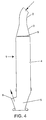
- Figure 4 shows a further example of a previously known device in which a grating 9 is provided in the area at the diffuser.
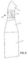
- FIG. 5 shows a blade structure 10 for mounting in the inlet pipe.
- the structure comprises six blades 11, each of which is formed by a single-curved plate. This gives a particularly simple structure.
- Figure 7 shows a conditioning device in which e.g. blades, as shown in figure 6, are implemented, flow lines 12 after this implementation being shown. It appears that the separation indicated in figure 2 no longer occurs. Also a secondary flow 13 directed toward the conditioning chamber is visible. This likewise appears from figure 8 which shows a speed profile through this upper area of the conditioning chamber. It appears that there is a relatively great speed close to the inner wall, which indicates that a hot gas flows here, and that there is thus little risk of water drop settlement. The secondary flow is shown as a negative speed. A water drop 14 is indicated as being entrained.
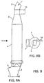
- Figure 9 shows an alternative embodiment of the invention, in which a tangential inlet 15 is provided in addition to the axial inlet 2. Both a downward flow and a rotating flow are provided hereby.
Landscapes
- Engineering & Computer Science (AREA)
- Chemical & Material Sciences (AREA)
- Chemical Kinetics & Catalysis (AREA)
- Mechanical Engineering (AREA)
- General Engineering & Computer Science (AREA)
- Treating Waste Gases (AREA)
- Separating Particles In Gases By Inertia (AREA)
- Instantaneous Water Boilers, Portable Hot-Water Supply Apparatuses, And Control Of Portable Hot-Water Supply Apparatuses (AREA)
- Preparation Of Clay, And Manufacture Of Mixtures Containing Clay Or Cement (AREA)
Description
Claims (7)
- A method for conditioning of flue gas where the flue gas is lead to a flue gas conditioning device comprising an inlet, (2) a diffuser (3) in extension of the inlet (2) and an essentially cylindrical pipe area (4) in extension of the diffuser (3), said pipe area (4) being equipped with a bottom and an outlet (6) opposite the diffuser (3), the inner walls of the diffuser (3) and the cylindrical pipe area (4) defining a conditioning chamber, means being provided in an area of the conditioning chamber near the inlet (2) to introduce conditioning water into the flue gas, providing an elevated temperature at the inner wall which defines the conditioning chamber, characterized in that the flue gas stream in the conditioning chamber is caused to perform a rotating movement with respect to an axis extending through the conditioning chamber,
that the flue gas is simultaneously caused to perform an axial movement, and that the speed of rotation constitutes between 10 and 40% of the axial speed. - A flue gas conditioning device (1) comprising an inlet (2), a diffuser (3) in extension of the inlet (2) and an essentially cylindrical pipe area (4) in extension of the diffuser (3), said pipe area (4) being equipped with a bottom and an outlet (6) opposite the diffuser (3), said diffuser (3) and said cylindrical pipe area (4) defining a conditioning chamber, means being provided in an area of the conditioning chamber near the inlet to introduce conditioning water into the flue gas, characterized in that means (10-15) to impart a rotating momentum and means to impart an axial momentum to the flue gas are provided, whereby the means to generate the rotating momentum and the means to generate the axial momentum are adapted such that the speed of rotation corresponds to 10-40% of the axial speed in the conditioning chamber.
- A flue gas conditioning device according to claim 2, characterized in that guide blades (11) are provided, said guide blades (11) extending radially in the inlet (2) and/or in the diffuser (3).
- A flue gas conditioning device according to claim 2 or 3 4, characterized in that a first essentially axial inlet pipe (2) is provided, and that, in association with this, a second tangentially directed flue gas inlet pipe (15) is provided.
- A flue gas conditioning device according to claim 3, characterized in that the guide blades (11) are single-curved plates in which the curvature extends transversely to the radial direction.
- A flue gas conditioning device according to claim 3 or 5, characterized in that between 2 and 12 blades (11) are provided, and that the blades (11) have a height of up to 2 inlet pipe diameters.
- The use of a conditioning device as defined in any one of claims 2-6 in a cement production system comprising a kiln, a mill, a flue gas conditioning device (1) and a separator.
Applications Claiming Priority (3)
| Application Number | Priority Date | Filing Date | Title |
|---|---|---|---|
| DK84297 | 1997-07-11 | ||
| DK84297 | 1997-07-11 | ||
| PCT/DK1998/000316 WO1999002241A1 (en) | 1997-07-11 | 1998-07-07 | A method of flue gas conditioning and a flue gas conditioning device |
Publications (2)
| Publication Number | Publication Date |
|---|---|
| EP1027134A1 EP1027134A1 (en) | 2000-08-16 |
| EP1027134B1 true EP1027134B1 (en) | 2002-09-11 |
Family
ID=8098171
Family Applications (1)
| Application Number | Title | Priority Date | Filing Date |
|---|---|---|---|
| EP98933567A Expired - Lifetime EP1027134B1 (en) | 1997-07-11 | 1998-07-07 | A method of flue gas conditioning and a flue gas conditioning device |
Country Status (12)
| Country | Link |
|---|---|
| EP (1) | EP1027134B1 (en) |
| KR (1) | KR20010021762A (en) |
| CN (1) | CN1268904A (en) |
| AU (1) | AU8333798A (en) |
| BR (1) | BR9810999A (en) |
| DE (1) | DE69807917D1 (en) |
| ES (1) | ES2178841T3 (en) |
| ID (1) | ID24886A (en) |
| PL (1) | PL338032A1 (en) |
| TR (1) | TR200000056T2 (en) |
| TW (1) | TW555726B (en) |
| WO (1) | WO1999002241A1 (en) |
Families Citing this family (1)
| Publication number | Priority date | Publication date | Assignee | Title |
|---|---|---|---|---|
| CN113337660A (en) * | 2021-05-27 | 2021-09-03 | 上海雷林工业设备有限公司 | Flue gas adjusting device |
Family Cites Families (4)
| Publication number | Priority date | Publication date | Assignee | Title |
|---|---|---|---|---|
| US2532260A (en) * | 1946-09-10 | 1950-11-28 | Martin H Lipton | Combined smoke generator and conditioner |
| DE1557108A1 (en) * | 1951-01-28 | 1970-04-30 | Kloeckner Humboldt Deutz Ag | Improved dedusting of exhaust gases |
| DE1551890C3 (en) * | 1967-04-29 | 1975-01-09 | Metallgesellschaft Ag, 6000 Frankfurt | Evaporative cooler |
| DE3111074A1 (en) * | 1981-03-20 | 1982-09-30 | Metallgesellschaft Ag, 6000 Frankfurt | Steam-generating plant with an exhaust-gas purification apparatus |
-
1998
- 1998-07-07 DE DE69807917T patent/DE69807917D1/en not_active Expired - Lifetime
- 1998-07-07 AU AU83337/98A patent/AU8333798A/en not_active Abandoned
- 1998-07-07 CN CN98807125A patent/CN1268904A/en active Pending
- 1998-07-07 KR KR1020007000325A patent/KR20010021762A/en not_active Withdrawn
- 1998-07-07 ID IDW20000012A patent/ID24886A/en unknown
- 1998-07-07 PL PL98338032A patent/PL338032A1/en unknown
- 1998-07-07 TR TR2000/00056T patent/TR200000056T2/en unknown
- 1998-07-07 EP EP98933567A patent/EP1027134B1/en not_active Expired - Lifetime
- 1998-07-07 BR BR9810999-5A patent/BR9810999A/en not_active IP Right Cessation
- 1998-07-07 ES ES98933567T patent/ES2178841T3/en not_active Expired - Lifetime
- 1998-07-07 WO PCT/DK1998/000316 patent/WO1999002241A1/en not_active Ceased
- 1998-09-19 TW TW087115687A patent/TW555726B/en active
Also Published As
| Publication number | Publication date |
|---|---|
| WO1999002241A1 (en) | 1999-01-21 |
| ES2178841T3 (en) | 2003-01-01 |
| ID24886A (en) | 2000-08-31 |
| PL338032A1 (en) | 2000-09-25 |
| DE69807917D1 (en) | 2002-10-17 |
| AU8333798A (en) | 1999-02-08 |
| BR9810999A (en) | 2000-08-08 |
| EP1027134A1 (en) | 2000-08-16 |
| KR20010021762A (en) | 2001-03-15 |
| TR200000056T2 (en) | 2002-08-21 |
| CN1268904A (en) | 2000-10-04 |
| TW555726B (en) | 2003-10-01 |
Similar Documents
| Publication | Publication Date | Title |
|---|---|---|
| AU706120B2 (en) | Gas transfer pipe arrangement | |
| US4289611A (en) | Multi-stage cyclone separator | |
| RU2447925C2 (en) | Drop separator | |
| US7896937B2 (en) | Hybrid separator | |
| US3976018A (en) | Dryer system | |
| US2182862A (en) | Separating method and apparatus | |
| WO1980001467A1 (en) | Diverging vortex separator | |
| CN103201099B (en) | cyclone separator | |
| CA2932359C (en) | External separator | |
| JPH1066897A (en) | Cyclone, especially cyclone dust collector and cyclone classifier | |
| US20020014707A1 (en) | Method of flue gas conditioning and a flue gas conditioning device | |
| EP0871003A1 (en) | Pulverized body drying method and apparatus | |
| JPH0561964B2 (en) | ||
| EP3559577B1 (en) | Powder drying system with improved inlet arrangement to the filter unit and method of operating the filter unit of such a system | |
| JP5497443B2 (en) | Material particle size selection and / or drying equipment | |
| EP0165668A1 (en) | Heat exchanger | |
| US3173771A (en) | Gas and liquid contact method and apparatus | |
| US20050076782A1 (en) | Gas scrubber | |
| CN1327482A (en) | Blast furnace gas dedusting device | |
| JP2006515533A (en) | Swirl tube separator | |
| JPWO2019230258A1 (en) | Separator | |
| EP1027134A1 (en) | A method of flue gas conditioning and a flue gas conditioning device | |
| JP2002528257A (en) | Fluid and particle separation apparatus and separation method | |
| CN219539840U (en) | Separator for dust-containing process gas | |
| KR100887159B1 (en) | Fly Ash Classifier |
Legal Events
| Date | Code | Title | Description |
|---|---|---|---|
| PUAI | Public reference made under article 153(3) epc to a published international application that has entered the european phase |
Free format text: ORIGINAL CODE: 0009012 |
|
| 17P | Request for examination filed |
Effective date: 20000211 |
|
| AK | Designated contracting states |
Kind code of ref document: A1 Designated state(s): BE DE ES FR GB GR IE NL PT |
|
| 17Q | First examination report despatched |
Effective date: 20010521 |
|
| GRAG | Despatch of communication of intention to grant |
Free format text: ORIGINAL CODE: EPIDOS AGRA |
|
| GRAG | Despatch of communication of intention to grant |
Free format text: ORIGINAL CODE: EPIDOS AGRA |
|
| GRAH | Despatch of communication of intention to grant a patent |
Free format text: ORIGINAL CODE: EPIDOS IGRA |
|
| GRAH | Despatch of communication of intention to grant a patent |
Free format text: ORIGINAL CODE: EPIDOS IGRA |
|
| GRAA | (expected) grant |
Free format text: ORIGINAL CODE: 0009210 |
|
| AK | Designated contracting states |
Kind code of ref document: B1 Designated state(s): BE DE ES FR GB GR IE NL PT |
|
| PG25 | Lapsed in a contracting state [announced via postgrant information from national office to epo] |
Ref country code: NL Free format text: LAPSE BECAUSE OF FAILURE TO SUBMIT A TRANSLATION OF THE DESCRIPTION OR TO PAY THE FEE WITHIN THE PRESCRIBED TIME-LIMIT Effective date: 20020911 Ref country code: GR Free format text: LAPSE BECAUSE OF FAILURE TO SUBMIT A TRANSLATION OF THE DESCRIPTION OR TO PAY THE FEE WITHIN THE PRESCRIBED TIME-LIMIT Effective date: 20020911 Ref country code: FR Free format text: LAPSE BECAUSE OF NON-PAYMENT OF DUE FEES Effective date: 20020911 Ref country code: BE Free format text: LAPSE BECAUSE OF FAILURE TO SUBMIT A TRANSLATION OF THE DESCRIPTION OR TO PAY THE FEE WITHIN THE PRESCRIBED TIME-LIMIT Effective date: 20020911 |
|
| REG | Reference to a national code |
Ref country code: GB Ref legal event code: FG4D |
|
| REG | Reference to a national code |
Ref country code: IE Ref legal event code: FG4D |
|
| REF | Corresponds to: |
Ref document number: 69807917 Country of ref document: DE Date of ref document: 20021017 |
|
| PG25 | Lapsed in a contracting state [announced via postgrant information from national office to epo] |
Ref country code: DE Free format text: LAPSE BECAUSE OF FAILURE TO SUBMIT A TRANSLATION OF THE DESCRIPTION OR TO PAY THE FEE WITHIN THE PRESCRIBED TIME-LIMIT Effective date: 20021212 |
|
| PG25 | Lapsed in a contracting state [announced via postgrant information from national office to epo] |
Ref country code: PT Free format text: LAPSE BECAUSE OF FAILURE TO SUBMIT A TRANSLATION OF THE DESCRIPTION OR TO PAY THE FEE WITHIN THE PRESCRIBED TIME-LIMIT Effective date: 20021217 |
|
| REG | Reference to a national code |
Ref country code: ES Ref legal event code: FG2A Ref document number: 2178841 Country of ref document: ES Kind code of ref document: T3 |
|
| NLV1 | Nl: lapsed or annulled due to failure to fulfill the requirements of art. 29p and 29m of the patents act | ||
| EN | Fr: translation not filed | ||
| PG25 | Lapsed in a contracting state [announced via postgrant information from national office to epo] |
Ref country code: IE Free format text: LAPSE BECAUSE OF NON-PAYMENT OF DUE FEES Effective date: 20030707 Ref country code: GB Free format text: LAPSE BECAUSE OF NON-PAYMENT OF DUE FEES Effective date: 20030707 |
|
| PLBE | No opposition filed within time limit |
Free format text: ORIGINAL CODE: 0009261 |
|
| STAA | Information on the status of an ep patent application or granted ep patent |
Free format text: STATUS: NO OPPOSITION FILED WITHIN TIME LIMIT |
|
| PGFP | Annual fee paid to national office [announced via postgrant information from national office to epo] |
Ref country code: ES Payment date: 20030813 Year of fee payment: 6 |
|
| 26N | No opposition filed |
Effective date: 20030612 |
|
| GBPC | Gb: european patent ceased through non-payment of renewal fee |
Effective date: 20030707 |
|
| REG | Reference to a national code |
Ref country code: IE Ref legal event code: MM4A |
|
| PG25 | Lapsed in a contracting state [announced via postgrant information from national office to epo] |
Ref country code: ES Free format text: LAPSE BECAUSE OF NON-PAYMENT OF DUE FEES Effective date: 20040708 |
|
| REG | Reference to a national code |
Ref country code: ES Ref legal event code: FD2A Effective date: 20040708 |