EP1026878A2 - Color electrophotographic apparatus and method of processing an image produced thereby - Google Patents
Color electrophotographic apparatus and method of processing an image produced thereby Download PDFInfo
- Publication number
- EP1026878A2 EP1026878A2 EP00300829A EP00300829A EP1026878A2 EP 1026878 A2 EP1026878 A2 EP 1026878A2 EP 00300829 A EP00300829 A EP 00300829A EP 00300829 A EP00300829 A EP 00300829A EP 1026878 A2 EP1026878 A2 EP 1026878A2
- Authority
- EP
- European Patent Office
- Prior art keywords
- halftone
- data
- image reproduction
- color
- dots
- Prior art date
- Legal status (The legal status is an assumption and is not a legal conclusion. Google has not performed a legal analysis and makes no representation as to the accuracy of the status listed.)
- Granted
Links
Images






Classifications
-
- H—ELECTRICITY
- H04—ELECTRIC COMMUNICATION TECHNIQUE
- H04N—PICTORIAL COMMUNICATION, e.g. TELEVISION
- H04N1/00—Scanning, transmission or reproduction of documents or the like, e.g. facsimile transmission; Details thereof
- H04N1/46—Colour picture communication systems
- H04N1/52—Circuits or arrangements for halftone screening
-
- H—ELECTRICITY
- H04—ELECTRIC COMMUNICATION TECHNIQUE
- H04N—PICTORIAL COMMUNICATION, e.g. TELEVISION
- H04N1/00—Scanning, transmission or reproduction of documents or the like, e.g. facsimile transmission; Details thereof
- H04N1/40—Picture signal circuits
- H04N1/405—Halftoning, i.e. converting the picture signal of a continuous-tone original into a corresponding signal showing only two levels
- H04N1/4055—Halftoning, i.e. converting the picture signal of a continuous-tone original into a corresponding signal showing only two levels producing a clustered dots or a size modulated halftone pattern
- H04N1/4058—Halftoning, i.e. converting the picture signal of a continuous-tone original into a corresponding signal showing only two levels producing a clustered dots or a size modulated halftone pattern with details for producing a halftone screen at an oblique angle
Definitions
- the present invention relates to a color electrophotographic apparatus which performs halftoning operations through use of halftone spots formed by a plurality of dots, a method of processing an image produced by the color photographic apparatus, and a recording medium having recorded thereon a program to be used for image processing.
- dot implies "pixel” defined as a unit cell in electrophotographic apparatuses.
- a color image is reproduced by utilization of cyan toner, magenta toner, yellow toner, and black toner.
- some page printers-which forms a latent image on a photosensitive drum by utilization of a laser beam develop the latent image by use of charged toner, and transfer an image formed from the thus developed toner onto transfer paper can change an area to be exposed by the laser beam within a dot in various manners.
- those page printers can reproduce a color image with high resolution and high gradation.
- a dithering method has been widely utilized as a binary-coding method to be used for reproducing the halftone of a gray-scale image.
- the dithering method by reference to conversion tables which are called dither matrices or threshold-value matrices and which define the correspondence between halftone data and image production data, a determination is made as to whether color spot is displayed in each dot or not. A dot is 'ON' when color spot is displayed and "OFF" when color spot is not displayed.
- Halftone spots are produced by one dot or some adjacent dots turning "ON", and halftones of the images are reproduced on the basis of the sizes of halftone spots.
- Dots are arranged in the direction of primary scanning in which a laser beam is moved for scanning (hereinafter referred to simply as a "primary-scanning direction") and in the direction of secondary scanning in which transfer paper is fed (hereinafter referred to simply as a “secondary-scanning direction”).
- primary-scanning direction a laser beam is moved for scanning
- secondary-scanning direction a direction of secondary scanning in which transfer paper is fed
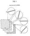
- FIG. 1 shows the combination of the angle of a cyan screen, the angle of a magenta screen, the angle of a yellow screen, and the angle of black screen, which has conventionally been used in wide applications of industrial printing systems.
- the angles of four color screens are set; specifically, the angle of the yellow (Y) screen is set to 0°; the angle of the cyan (C) screen [or the angle of the magenta (M) screen] is set to 15°; the angle of the black (K) screen is set to 45°; and the angle of the magenta (M) screen [or the angle of the cyan (C) screen] is set to 75°.
- the angle of the cyan screen is set to 15°, and the angle of the magenta screen is set to 75°.
- the angle of the yellow screen is set to 0°.
- the yellow screen is set to the longitudinal direction or the horizontal direction that are most noticeable to the human eye, the yellow screen does not become greatly noticeable, because yellow is least noticeable to the human eye.
- the industrial printing system is designed so as to prevent a moiré pattern by setting the magenta or cyan screen to an angle of 15° or 75° and rotating the color screens. Since the color screens are only rotated, exactly as they are, the pitch among halftone spots is maintained uniform throughout the 4 colors.
- the pattern of dots which can be developed by an engine for developing an actual image on the basis of image reproduction data, is limited to the direction of primary scanning in which a laser beam is actuated for scanning, as well as to the direction of secondary scanning in which paper is fed.
- the electrophotographic apparatus is incapable of rotating the color screens to arbitrary angles. Accordingly, in the electrophotographic apparatus, desired screen angles are achieved by shifting the positions of the dither matrices to be used for the dithering method in primary or secondary scanning direction, or by changing the data in the conversion table, as required.
- FIG. 2 is an illustration for describing a conventional method of determining screen angles in dithering method.
- dither matrices 40 are shifted such that in a horizontal row of dither matrices 40, each dither matrix 40 is vertically shifted from the preceding dither matrix 40 by a given amount, such that after four shifts the last dither in the row is vertically shifted by an amount corresponding to the height of one dither matrix 40.
- a dither matrix 42 designated by broken lines comprises a plurality of dither matrices 40. It is possible to determine the screen angle at an arbitrary value with higher degree of freedom by means of such a large dither matrix 42.
- a screen angle of 15° for magenta and a screen angle of 75° for cyan, which are deemed to contributed to the best picture quality in the printing industry, are related to an irrational tangent (i.e., a tangent which is an irrational number). Angles related to the irrational tangent cannot be reproduced, so long as a limited number of dots arranged in both the direction of primary scanning and the direction of secondary scanning are utilized.
- Another conceivable approach toward selecting angles which are related to the rational tangent and close to 15° and 75° is to increase the size of the dither matrices 42.
- the number of dots per unit area which the engine can process is as small as, e.g., 600 dpi (dots per inch). If the size of the dither matrices is increased, halftone spot pitch increases and screen frequency is diminished. Further, an increase in the size of dither matrices also results in an increase in the number of corresponding required ⁇ tables. Such an increase in the number of ⁇ tables in turn involves an increase in the volume of a recording medium for recording the conversion tables. Eventually, the cost of the electrophotographic apparatus is increased.
- the pitch between halftone spots among the color screens of different angles cannot be made uniform. Even in this respect, the electrophotographic apparatus encounters difficulty providing the same picture quality as that provided by the industrial printing system.
- An object of the present invention is to provide an electrophotographic apparatus capable of achieving screen angles related to an irrational tangent, a method of processing an image produced by the electrophotographic apparatus, and a recording medium on which an image processing program is recorded, with regard to a color electrophotographic apparatus which reproduces an image by utilization of halftone spots formed from a plurality of dots.
- Another object of the present invention is to provide an electrophotographic apparatus capable of making uniform pitches of halftone spots in a screen compatible with a plurality of colors, a method of processing an image produced by the electrophotographic apparatus, and a recording medium on which an image processing program is recorded, with regard to a color electrophotographic apparatus which reproduces an image by utilization of halftone spots formed from a plurality of dots.
- Still another object of the present invention is to achieve the objects through use of a reduced number of conversion tables.
- An image reproduction engine which causes toner to adhere to a development region of certain area located at a certain position within dots according to image reproduction data is utilized for image processing, wherein a halftone is expressed by means of halftone spots formed from a plurality of dots.
- the centroid of a halftone spot formed from a single dot or a plurality of adjacent dots can be shifted from the center of the dot to an arbitrary position, thus achieving desired screen angles or desired dot pitches.
- screen angles related to an irrational tangent can be realized, and the pitches of halftone spots of a plurality of color screens can also be made uniform.
- the present invention enables the position and area where the laser beam is radiated to be controllably changed to an arbitrary position and area for each dot, by producing a laser drive pulse signal according to image reproduction data by means of pulse-width modulation (PWM), as required.
- PWM pulse-width modulation
- the present invention utilizes an index-type conversion table.
- the conversion table comprises a plurality of ⁇ tables defining the correspondence between halftone data and image reproduction data, and a pattern matrix which includes reference data representing ⁇ tables to be referred to so as to correspond to a matrix including a plurality of dots.
- some of reference data sets in the pattern matrix can be identical, and a single ⁇ table can be referred to by a plurality of dots within the pattern matrix.
- the present invention provides a color electrophotographic apparatus which reproduces an image by utilization of a plurality of color toners and by expressing halftone of each color through use of halftone spots formed from a plurality of dots
- the apparatus comprising: a halftone processing section which is provided with halftone data for respective colors and which reproduces the image reproduction data corresponding to the dots on the basis of the halftone data by reference to a conversion table defining the correspondence between the halftone data prepared so as to correspond to the dots and image reproduction data; and an image reproduction engine which is provided with a drive signal corresponding to the image reproduction data and which causes the toners to adhere to a development region whose area and location correspond to the image reproduction data, within the dots, wherein the halftone processing section prepares the image reproduction data to be used for changing the angle of one color screen of the plurality of color screens to substantially an angle related to an irrational tangent.
- the present invention provides a color electrophotographic apparatus which reproduces an image by utilization of a plurality of color toners and by expressing halftone of each color through use of halftone spots formed from a plurality of dots
- the apparatus comprising: a halftone processing section which is provided with halftone data for respective colors and which reproduces the image reproduction data corresponding to the dots on the basis of the halftone data by reference to a conversion table defining the correspondence between the halftone data prepared so as to correspond to the dots and image reproduction data, and an image reproduction engine which is provided with a drive signal corresponding to the image reproduction data and which causes the toners to adhere to a development region whose area and location correspond to the image reproduction data, within the dots, wherein the halftone processing section prepares the image reproduction data to be used for making the distances among the centers of the halftone spots of the plurality of colors substantially equal.
- the present invention also provides a recording medium which reserves an image processing method for use with the foregoing electrophotographic apparatus and a program used for effecting image processing.
- FIG. 3 shows an example of a halftone spot according to the first embodiment of the present invention.
- a single halftone spot SP is produced by formation of a development region designated as a shaded area, within dots D1 to D6 produced at; e.g., 600 dpi.
- Formation of the halftone spot will be described by reference to electrophotographic system, in which a laser diode is activated on the basis of image reproduction data in accordance with a drive pulse modulated by a pulse-width modulation method, to thereby radiate a resultant laser beam.
- the laser beam is radiated onto the dot D1 such that toner adheres to a region encompassing approximately the rightmost one-fourth of the dot (hereinafter called "rightmost one-fourth region").
- the diameter of the laser beam is equal to; e.g., the longitudinal length of the dot, and the laser beam is radiated onto a desired region while being scanned in the transverse direction of FIG. 3.
- the drive pulse for driving the laser is imparted with a timing and a width corresponding to approximately the rightmost one-fourth region.
- the development position can be controlled by controlling the timing, and the area of development can be controlled by controlling the pulse width.
- a dot D2 is adjacent to the dot D1, and the laser beam is radiated onto a region encompassing approximately the leftmost one-tenth of the dot D2.
- the development region of predetermined width is realized by connection of the irradiated region of the adjacent dot D1 to the irradiated region of the dot D2.
- the entirety of a dot D3 is exposed to the laser beam.
- the laser beam is radiated onto a region encompassing approximately the leftmost two-thirds of an adjacent dot D4.
- a wide development region is formed by connection of the irradiated region of the dot D3 to the irradiated region of the dot D4.
- the laser beam is radiated onto a region encompassing approximately the rightmost one-half of a dot D5, and the laser beam is radiated onto a region encompassing approximately the leftmost one-fourth region of a dot D6.
- the halftone spot SP shown in FIG. 3 is characterized in that the development region formed from the dots D1 and D2 is narrower than the development region formed from the dots D5 and D6 and that the development region formed from the adjacent dots D1 and D2, the development region formed from the adjacent dots D3 and D4, and the development region formed from the adjacent dots D5 and D6 are shifted leftward.
- the centroid of the halftone spot SP formed from the dots D1 to D6 i.e., the center of the halftone spot SP
- X shown in the drawing.
- the halftone spot SP to be finally reproduced becomes more rounded than the shaded region shown in FIG. 3, by means of the shape of the laser beam or the adhering characteristic of toner.
- the center of the halftone spot can be placed at an arbitrary position without regard to arrangement of dots, by setting the positions and areas within dots to be exposed to the laser beam, as required.
- a development region of arbitrary area can be produced at an arbitrary location within a dot, by means of controlling the timing and width of a pulse signal used for driving the laser.
- Utilization of such a development method and formation of a halftone spot through use of development regions of a plurality of dots enables controllable changing of the position of the halftone spot to an arbitrary position, without regard to the pitch and arrangement of dots.
- the present invention enables formation of a halftone spot at an arbitrary position and realization of screen angles related to an irrational tangent and arbitrary pitch of the halftone spots.
- FIG. 4 is an example of a halftone spot which is formed on the basis of the foregoing principle and is grown according to the first embodiment.
- FIG. 4 shows a plurality of halftone spots to be formed from dots D 1,1 to D 12,12 of a matrix pattern having 12 rows and 12 columns.
- a conversion table defining the correspondence between halftone data of dots and image reproduction data assumes the form of a 12x12 matrix.
- Each halftone spot may be formed from four adjacent dots, six adjacent dots, or from some other number of dots.
- the center of the halftone spot is set at a desired location without regard to the pitch or arrangement of dots.
- the coordinates of a halftone spot SP1 are set to (8.2, 2.0), and the coordinates of a halftone spot SP2 are set to (10.5, 10.7).
- the halftone spot SP1 is formed from four adjacent dots
- the halftone spot SP2 is formed from nine adjacent dots.
- a screen angle defined by the two halftone spots SP1 and SP2 (i.e., the angle of a line connecting the halftone spots) is 14.81° with reference to the Y axis.
- the screen angle is very close to an angle of 15°; an angle related to an irrational tangent.
- the distance between the two halftone spots SP1 and SP2 is 9.0 dots long. Since two halftone spots exist between the halftone spots SP1 and SP2, the pitch between the halftone spots shown in FIG. 4 (i.e., the linear distance between the halftone spots) assumes a pitch of 3.0 dots. In the screen whose angle is 0°, realization of a pitch of 3.0 dots is easy. Therefore, the example screen of FIG. 4 can be used as a rotated screen of 0° screen with the same halftone spot pitch (3.0 dots).
- the screen angles of 15° and 45° shown in FIG. 1 can be realized.
- the pitch of halftone spots can also be set to a value of 3.0 dots, in the same manner as in the previous example of FIG. 4.
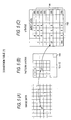
- FIG. 5 is schematic representation showing a conversion table used in the first embodiment.
- the conversion table is ordinarily stored in a halftone processing section provided within an internal controller of an electrophotographic apparatus.
- Image data shown in FIG. 5(A) comprise halftone data for respective colors corresponding to dots.
- the halftone data may correspond to a color space of RGB or to a color space of CMYK.
- CMYK toners are commonly used in a color electrophotographic apparatus.
- the image data comprise halftone data corresponding to Y, M, C, and K, respectively.
- a pattern matrix shown in FIG. 5(B) and ⁇ tables shown in FIG. 5(C) are applied to such image data.
- the pattern matrix consists of 12 rows by 12 columns.
- the pattern matrix in FIG. 5(B) contains the reference numbers "i" to the ⁇ table. For instance, given that the reference number of the pattern matrix corresponding to a dot P of image data is 27, image reproduction data corresponding to the dot P are determined by reference to the ⁇ table whose reference number 27. Specifically, image reproduction data (an output value) corresponding to halftone data of image data (an input level) are read by reference to the ⁇ table corresponding to reference number 27.
- the engine utilizing a laser beam is provided with a laser drive pulse signal modulated by the pulse-width modulation method, activates a laser diode in accordance with the drive pulse, and radiates a laser beam onto a photosensitive drum. Consequently, a laser beam is radiated onto only a region of desired area on the left or right side within a dot, and toner adheres to the thus-irradiated region.
- the image reproduction data output from the ⁇ table comprise data pertaining to whether the region to be irradiated is on the left or right side of the dot, as well as pulse width data corresponding to the area of the region to be irradiated.
- FIG. 6 is an illustration showing an example of the pattern matrix according to the first embodiment.
- the pattern corresponds to a matrix having 12 rows and 12 columns.
- a total of 144 reference numbers (1 to 144) are assigned to elements of the matrix without involvement of an overlap.
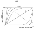
- FIG. 7 is a diagrammatic representation of an example of the ⁇ table according to the first embodiment.
- input levels of halftone data are associated with outputs including image reproduction data pertaining to whether the right or the left side of the dot is to be irradiated with a laser beam and data pertaining to the extent to which the region is to be irradiated.
- the ⁇ table assigned to reference number "j" converts low-level input data into high-level output data and corresponds to a dot in the pattern matrix which grows when the input level of the image data is comparatively low.
- the ⁇ table assigned to reference number "m” converts input data into output data so as to be in proportion to the input data and corresponds to a dot in the pattern matrix which grows when the input level of the image data is comparatively intermediate level.
- the ⁇ table assigned to reference number "p” corresponds to a dot which does not grow when the input level of image data is low but grows when the input level of the image data has reached a comparatively high level.
- ⁇ tables of 144 types are associated with the pattern matrix having 12 rows and 12 columns. Consequently, the ⁇ table shown in FIG. 7 also comprises ⁇ curves of 144 types.
- An enormous pattern matrix such as 1000x1000 theoretically enables to realize screens with angles related to the irrational tangent or screen sets with equal halftone spot pitch among the screens of different angles.
- the electrophotographic apparatus such as a color page printer cannot utilize such a pattern matrix of enormous magnitude.
- the pitch between halftone spots becomes too long (consequently, the screen frequency is reduced), so that the resolution of the resultant reproduced image is deteriorated drastically.
- the development region which is located at a desired position within a dot and has a desired area, is controlled on the basis of the image reproduction data.
- the position of a halftone spot to grow is controllably set to an arbitrary position where the halftone spot is not limited by the dot pitch or the arrangement of dots, thus achieving screen angles related to the irrational tangent or a uniform pitch of halftone spots.
- the total number of ⁇ tables is diminished by collecting, into a single table, ⁇ tables assigned the same output for an input level.
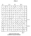
- FIG. 8 shows index-type conversion table according to the second embodiment.
- an index of the ⁇ table is assigned to respective elements of the pattern matrix.
- the ⁇ table is sought by reference to an index table. Consequently, a single ⁇ table can be shared among a plurality of elements of the pattern matrix, and the number of ⁇ tables can be set to a small value independently of the pattern matrix.
- dots appear, in the form of completely identical patterns, in positions spaced apart from one another by a given distance in the longitudinal direction and a given distance in the lateral direction. Accordingly, dots can be designated within a square matrix of finite size without involvement of errors. Further, dots appear within the square matrix in the form of completely identical patterns. In this sense, the index-type conversion table is advantageous in the case of the rational tangent screen.
- 144 ⁇ tables are classified into a group of tables corresponding to halftone spots whose right portions are development regions (i.e., regions exposed to a laser beam) and another group of matrices corresponding to halftone spots whose left portions are development regions.
- ⁇ tables with similar input-output correspondence are collected.
- the thus-collected adjacent ⁇ tables are assigned a single index.
- FIG. 9 is an illustration showing an example of a pattern matrix according to the second embodiment.
- the pattern matrix shown in FIG. 9 represents, in the form of a single pattern matrix, the pattern matrix shown in FIG. 8(B) and the index table shown in FIG. 8(C).
- different ⁇ tables are assigned to all the elements of the matrix having 12 rows and 12 columns.
- ⁇ tables of 36 types are assigned to 144 elements of the matrix having 12 rows and 12 columns.
- Numbers assigned to 144 elements shown in FIG. 9 designate indices of the ⁇ tables.
- ⁇ tables are understood to be assigned to the elements in an overlapping manner.
- the ⁇ table assigned number 1 is allocated to elements D 1,1 , D 1,4 , D 2,7 , D 3,10 , D 7,12 , and D 10,11 of the pattern matrix.
- the total number of ⁇ tables can be diminished by collecting ⁇ tables assigned to dots whose development regions are on the same side and which output substantially the same value in response to an input. Specifically, the adjacent ⁇ tables of the ⁇ tables shown in FIG. 7 are collected into a single group.
- FIG. 10 shows an example of halftone spots that have been grown according to the second embodiment.
- the development regions formed in respective dots differ in position and area from one dot to another. Consequently, the center coordinates of the grown halftone spot SP1 are (8.2, 2.0), and the center coordinates of the grown halftone spot SP2 are (10.5, 10.7).
- the halftone spots SP1 and SP2 can be placed in the same positions as those shown in FIG. 4.
- the screen angle ⁇ assumes a value of about 15°
- the pitch of the halftone dot assumes a value of 3.0, as in the case of the example shown in FIG. 4.
- the dots D 1,1 , D 1,4 , D 2,7 , D 3,10 , D 7,12 , and D 10,11 shown in FIG. 4 correspond to dots whose right-side portions are developed or remain substantially undeveloped.
- the right-side portions of all the dots are developed to the same area.
- FIG. 11 is a schematic diagram showing the configuration of an electrophotographic system.
- a host computer 50 produces image data 56 comprising RGB halftone data (each data set including eight bits, and the halftone data comprise a total of 24 bits).
- the RGB halftone data are delivered to an electrophotographic apparatus 60 such as a page printer.
- the electrophotographic apparatus 60 reproduces a color image.
- the electrophotographic apparatus 60 comprises a controller 62 which processes an image and supplies laser drive data 69 to an engine, and an engine 70 which reproduces an image according to the drive data 69.
- the host computer 50 produces text data, graphic data, bit-map data or the like.
- the data sets produced by the application program 52 are rasterized by means of a electrophotographic apparatus driver software 54 installed in the host computer 50.
- the thus-rasterized data sets are converted into the image data 56, each pixel or dot of which comprises respective RGB halftone data sets.
- the electrophotographic apparatus 60 is provided with an unillustrated built-in microprocessor, and the microprocessor, in combination with a control program installed therein, constitutes a controller 62 including a color conversion section 64, a halftone processing section 66, and a pulse-width modulation section 68.
- the engine 70 e.g., a laser driver 72, activates a laser diode 74 for drawing an image on the basis of the drive data 69.
- the engine 70 comprises a photosensitive drum, a transfer belt, and a drive section, these elements are omitted from FIG. 11.
- the color conversion section 64 provided within the controller 62 converts RGB halftone data 56 that are supplied for each dot, into CMYK halftone data 10 which are complementary to the RGB data.
- each color halftone data set comprises 8 bits and a maximum of 256 gray scales.
- the color conversion section 64 converts the RGB halftone data 56 for each dot into the halftone data 10 for each plane dot of the respective CMYK colors. Consequently, the halftone processing section 66 is supplied with the halftone data 10 corresponding to a plane dot of the respective color.
- the halftone processing section 66 produces, from the halftone data 10 for each dot, the image reproduction data 30 for each dot.
- the halftone processing section 66 produces the image reproduction data 30, which represent halftones, by utilization of; e.g., a multivalued dithering method.
- the halftone processing section 66 can produce the image reproduction data 30 which represent the right or left region and the area of the region.
- a color printer of as low dot per inch as 600 dpi is possible to have a high resolution by a high frequency screen with small spot pitch, and also halftone processing section 66 can set the center of a halftone spot at an arbitrary position regardless of the position of the dot.
- halftone processing section 66 can set the center of a halftone spot at an arbitrary position regardless of the position of the dot.
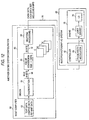
- FIG. 12 is a schematic diagram showing another configuration of the electrophotographic system. This configuration corresponds to a modification of the system configuration shown in FIG. 11.
- a driver software 80 installed in the host computer 50 has a rasterization function 54, the color conversion function 64, and the halftone processing function 66. These functions 54, 64, and 66 are analogous to the functions of the elements assigned the same reference numerals shown in FIG. 11.
- the image reproduction data 30 produced for each color by means of the halftone processing function 64 are supplied to the pulse-width modulation section 68 of the controller 62 provided within the electrophotographic apparatus 60, such as a page printer, where the data are converted into the desired drive data 69 and delivered to the engine 70.
- the driver software 80 installed in the host computer 50 performs color conversion and halftone processing operations.
- the controller provided within the electrophotographic system performs color conversion and halftone processing operations.
- the host computer 50 performs conversion and halftone processing operations. If demand exists for the electrophotographic apparatus 60 to be inexpensive, the price of the apparatus is required to be diminished by reducing the capability of the controller 62. In such a case, an effective measure is to implement the color conversion processing and the halftone processing, which are portions of the functions offered by the controller shown in FIG. 11, by means of the driver program installed in the host computer. In a case where the driver 80 performs halftone processing, the storage medium having recorded thereon a program for causing the computer to perform the foregoing halftone processing procedures is incorporated into the host computer 50.
- the present invention enables the electrophotographic device capable of reproducing only a limited dot density to materialize screen angles substantially related to an irrational tangent with a small pitch of halftone spots and high resolution. Further, the all pitches of halftone spots of different color screens having different angles can be made substantially equal at a limited dot density.
Landscapes
- Engineering & Computer Science (AREA)
- Multimedia (AREA)
- Signal Processing (AREA)
- Facsimile Image Signal Circuits (AREA)
- Color, Gradation (AREA)
- Color Image Communication Systems (AREA)
- Color Electrophotography (AREA)
- Image Processing (AREA)
- Fax Reproducing Arrangements (AREA)
- Photoreceptors In Electrophotography (AREA)
- Developing Agents For Electrophotography (AREA)
Abstract
Description
Claims (12)
- A color electrophotographic apparatus which reproduces an image by utilization of a plurality of color toners and by expressing halftone of each color through use of halftone spots formed from a plurality of dots, said apparatus comprising:a halftone processing section which is provided with halftone data for respective colors and which reproduces image reproduction data by reference to a conversion table defining a correspondence between the halftone data and image reproduction data; andan image reproduction engine which is provided with a drive signal corresponding to the image reproduction data to thereby cause the toners to adhere to a development region whose area and location correspond to the image reproduction data, within the dots,
wherein said halftone processing section prepares the image reproduction data to be used for changing an angle of at least one color screen of a plurality of color screens to substantially an angle related to an irrational tangent. - A color electrophotographic apparatus according to claim 1, wherein said image reproduction engine radiates a beam to the development region to thereby causes the toners to adhere to the development region, andthe image reproduction data comprise data pertaining to a position and an area to be exposed within the dot in a scanning direction of the beam.
- A color electrophotographic apparatus according to claim 1, wherein the conversion table comprisesa plurality of γ tables each defining the correspondence between the halftone data and the image reproduction data; anda pattern matrix having reference data, which reference data show the γ table to be referred to in response to the matrix having the plurality of dots.
- A color electrophotographic apparatus according to claim 3, wherein a partial overlap exists in the reference data provided within the pattern matrix, and a single γ table is referred to by the plurality of dots within the pattern matrix.
- A color electrophotographic apparatus which reproduces an image by utilization of a plurality of color toners and by expressing halftone of each color through use of halftone spots formed from a plurality of dots, said apparatus comprising:a halftone processing section which is provided with halftone data of respective colors and which reproduces the image reproduction data corresponding to the dots on the basis of the halftone data by reference to a conversion table defining a correspondence between the halftone data and image reproduction data; andan image reproduction engine which is provided with a drive signal corresponding to the image reproduction data to thereby cause the toners to adhere to a development region whose area and location correspond to the image reproduction data, within the dots,
wherein said halftone processing section prepares the image reproduction data to be used for making distances among centroids of the halftone spots of the plurality of colors substantially equal. - A color electrophotographic apparatus according to claim 5, wherein said image reproduction engine radiates a beam to the development region to thereby causes the toners to adhere to the development region, andthe image reproduction data comprise data pertaining to a position and an area to be exposed within the dot in a scanning direction of the beam.
- A color electrophotographic apparatus according to claim 5, wherein the conversion table comprisesa plurality of γ tables each defining the correspondence between the halftone data and the image reproduction data; anda pattern matrix having reference data, which reference data show the γ table to be referred to in response to the matrix having the plurality of dots.
- A color electrophotographic apparatus according to claim 7, wherein a partial overlap exists in the reference data provided within the pattern matrix, and a single γ table is referred to by the plurality of dots within the pattern matrix.
- A method of processing an image of color electrophotography by utilization of a plurality of color toners and by expressing halftone of each color through use of halftone spots formed from a plurality of dots, said method comprising:a halftone processing process, in which halftone data are provided for respective colors and the image reproduction data corresponding to the dots are produced on the basis of the halftone data by reference to a conversion table defining the correspondence between the halftone data and image reproduction data; andan image reproduction process, in which a drive signal corresponding to the image reproduction data is provided and the toners are caused to adhere to a development region whose area and location correspond to the image reproduction data, within the dots,
wherein, in the halftone processing process, there are produced the image reproduction data to be used for changing an angle of at least one color screen of a plurality of color screens to substantially an angle related to an irrational tangent. - A method of processing an image of color electrophotography by utilization of a plurality of color toners and by expressing halftone of each color through use of halftone spots formed from a plurality of dots, said method comprising:a halftone processing process, in which halftone data of respective colors are provided and the image reproduction data corresponding to the dots are reproduced on the basis of the halftone data by reference to a conversion table defining the correspondence between the halftone data and image reproduction data; andan image reproduction process, in which a drive signal corresponding to the image reproduction data is provided and the toners are caused to adhere to a development region whose area and location correspond to the image reproduction data, within the dots,
wherein, in the halftone processing process, there are prepared the image reproduction data to be used for making distances among centroids of the halftone spots of the plurality of colors substantially equal. - A recording medium having recorded thereon an image processing program used for causing a computer to perform color electrophotographic image processing procedures for reproducing an image by utilization of a plurality of color toners and by expressing halftone of each color through use of halftone spots formed from a plurality of dots, said image processing procedures comprising:a halftone processing procedure, in which halftone data are provided for respective colors and the image reproduction data corresponding to the dots are produced on the basis of the halftone data by reference to a conversion table defining the correspondence between the halftone data and image reproduction data,
wherein the image reproduction data comprise data pertaining to a position and area to be exposed within the dot in the scanning direction of the beam, and the halftone processing procedures produces the image reproduction data to be used for changing an angle of at least one color screen of a plurality of color screens to substantially an angle related to an irrational tangent. - A recording medium having recorded thereon an image processing program used for causing a computer to perform color electrophotographic image processing procedures for reproducing an image by utilization of a plurality of color toners and by expressing halftone of each color through use of halftone spots formed from a plurality of dots, said image processing procedures comprising:halftone processing procedures, in which halftone data of respective colors are provided and the image reproduction data corresponding to the dots are reproduced on the basis of the halftone data by reference to a conversion table defining the correspondence between the halftone data and image reproduction data,
wherein the image reproduction data comprise data pertaining to a position and area to be exposed within the dot in a scanning direction of the beam, and the halftone processing procedures produces the image reproduction data to be used for making distances among the centroids of the halftone spots of the plurality of colors substantially equal.
Applications Claiming Priority (2)
| Application Number | Priority Date | Filing Date | Title |
|---|---|---|---|
| JP2866699 | 1999-02-05 | ||
| JP02866699A JP3835037B2 (en) | 1999-02-05 | 1999-02-05 | Color electrophotographic image processing method and electrophotographic apparatus thereof |
Publications (3)
| Publication Number | Publication Date |
|---|---|
| EP1026878A2 true EP1026878A2 (en) | 2000-08-09 |
| EP1026878A3 EP1026878A3 (en) | 2002-01-02 |
| EP1026878B1 EP1026878B1 (en) | 2006-08-02 |
Family
ID=12254849
Family Applications (1)
| Application Number | Title | Priority Date | Filing Date |
|---|---|---|---|
| EP00300829A Expired - Lifetime EP1026878B1 (en) | 1999-02-05 | 2000-02-03 | Color electrophotographic apparatus and method of processing an image produced thereby |
Country Status (5)
| Country | Link |
|---|---|
| US (2) | US6791715B1 (en) |
| EP (1) | EP1026878B1 (en) |
| JP (1) | JP3835037B2 (en) |
| AT (1) | ATE335360T1 (en) |
| DE (1) | DE60029651T2 (en) |
Cited By (3)
| Publication number | Priority date | Publication date | Assignee | Title |
|---|---|---|---|---|
| EP1079603A3 (en) * | 1999-08-23 | 2002-08-07 | Seiko Epson Corporation | Method and apparatus for providing halftoning processing of color images |
| EP1439690A2 (en) | 2003-01-15 | 2004-07-21 | Xerox Corporation | Multi-bit output sampled threshold array halftoner |
| US6992795B1 (en) | 1999-02-25 | 2006-01-31 | Seiko Epson Corporation | Electrophotographic apparatus and electrophotograph image processing method |
Families Citing this family (8)
| Publication number | Priority date | Publication date | Assignee | Title |
|---|---|---|---|---|
| KR100538227B1 (en) * | 2003-07-26 | 2005-12-21 | 삼성전자주식회사 | Method of removing Moire pattern in 3D image displaying apparatus using complete parallax |
| JP4229017B2 (en) | 2004-07-15 | 2009-02-25 | セイコーエプソン株式会社 | Image processing apparatus, image processing method, and image processing program |
| JP4682770B2 (en) * | 2005-09-21 | 2011-05-11 | 富士ゼロックス株式会社 | Image forming apparatus |
| US7382994B2 (en) * | 2005-09-29 | 2008-06-03 | Lexmark International, Inc. | Background energy density control in an electrophotographic device |
| US7555252B2 (en) | 2006-01-17 | 2009-06-30 | Seiko Epson Corporation | Image forming apparatus that prevents conspicuous unevenness in image density |
| JP6083314B2 (en) * | 2013-05-01 | 2017-02-22 | コニカミノルタ株式会社 | Image forming apparatus |
| JP6338480B2 (en) * | 2014-07-22 | 2018-06-06 | 株式会社Screenホールディングス | Color conversion apparatus and color conversion method |
| US10477068B2 (en) * | 2016-03-18 | 2019-11-12 | Ricoh Company, Ltd. | Image processing apparatus for primary color and spot halftoning |
Family Cites Families (15)
| Publication number | Priority date | Publication date | Assignee | Title |
|---|---|---|---|---|
| JPS57171337A (en) | 1981-04-14 | 1982-10-21 | Dainippon Screen Mfg Co Ltd | Production of halftone plate picture |
| EP0711067A3 (en) * | 1989-11-21 | 1996-07-10 | Toyo Ink Mfg Co | Process for the formation of density patterns for the reproduction of binary gradations |
| GB9009406D0 (en) * | 1990-04-26 | 1990-06-20 | Zed Instr Ltd | Printing cylinder engraving |
| EP0740458B1 (en) * | 1991-02-08 | 2002-06-19 | Adobe Systems Inc. | Method of controlling dot size in digital halftoning with multi-cell threshold arrays |
| DE69322914T2 (en) | 1992-08-17 | 1999-07-29 | Bayer Corp., Agfa Division, Wilmington, Ma. | Raster filter and generating device and method therefor |
| JP3391847B2 (en) * | 1993-06-30 | 2003-03-31 | キヤノン株式会社 | Image forming apparatus and image forming method |
| BE1007264A4 (en) * | 1993-07-12 | 1995-05-02 | Agfa Gevaert Nv | Grid method for writing system with reduced density resolution. |
| DE69425244T2 (en) * | 1994-04-27 | 2001-01-25 | Agfa-Gevaert N.V., Mortsel | Tone-dependent rosette structures in multi-layer halftone screening using phase modulation |
| EP0680195B1 (en) * | 1994-04-27 | 2002-08-07 | Agfa-Gevaert | Clustered dot and line multilevel halftoning for electrographic colour printing |
| JP2815087B2 (en) | 1994-07-07 | 1998-10-27 | 富士ゼロックス株式会社 | Multicolor image forming apparatus and method |
| JPH0869139A (en) | 1994-08-30 | 1996-03-12 | Canon Inc | Image forming method and apparatus |
| JPH1075375A (en) | 1996-05-20 | 1998-03-17 | Fuji Xerox Co Ltd | Image processing unit, image processing system, and method for generating image processing screen |
| JP3156605B2 (en) * | 1996-11-19 | 2001-04-16 | セイコーエプソン株式会社 | Apparatus and method for generating pulse width data for toner transfer type printing apparatus |
| US5892891A (en) * | 1996-11-20 | 1999-04-06 | Xerox Corporation | System for printing color images with extra colorants in addition to primary colorants |
| DE19722697A1 (en) * | 1997-05-30 | 1998-12-03 | Heidelberger Druckmasch Ag | Process for digital screening of halftone images with screens of any screen width and screen angle |
-
1999
- 1999-02-05 JP JP02866699A patent/JP3835037B2/en not_active Expired - Fee Related
-
2000
- 2000-02-03 DE DE60029651T patent/DE60029651T2/en not_active Expired - Lifetime
- 2000-02-03 EP EP00300829A patent/EP1026878B1/en not_active Expired - Lifetime
- 2000-02-03 AT AT00300829T patent/ATE335360T1/en not_active IP Right Cessation
- 2000-02-04 US US09/497,518 patent/US6791715B1/en not_active Expired - Lifetime
-
2004
- 2004-04-12 US US10/821,946 patent/US7355756B2/en not_active Expired - Fee Related
Cited By (6)
| Publication number | Priority date | Publication date | Assignee | Title |
|---|---|---|---|---|
| US6992795B1 (en) | 1999-02-25 | 2006-01-31 | Seiko Epson Corporation | Electrophotographic apparatus and electrophotograph image processing method |
| EP1032190B1 (en) * | 1999-02-25 | 2006-09-13 | Seiko Epson Corporation | Electrophotographic apparatus and electrophotograph image processing method |
| EP1079603A3 (en) * | 1999-08-23 | 2002-08-07 | Seiko Epson Corporation | Method and apparatus for providing halftoning processing of color images |
| US6864996B1 (en) | 1999-08-23 | 2005-03-08 | Seiko Epson Corporation | Image processor and image processing method, and printer system equipped with image processor |
| EP1439690A2 (en) | 2003-01-15 | 2004-07-21 | Xerox Corporation | Multi-bit output sampled threshold array halftoner |
| EP1439690B1 (en) * | 2003-01-15 | 2012-04-18 | Xerox Corporation | Multi-bit output sampled threshold array halftoner |
Also Published As
| Publication number | Publication date |
|---|---|
| JP2000228728A (en) | 2000-08-15 |
| US7355756B2 (en) | 2008-04-08 |
| EP1026878A3 (en) | 2002-01-02 |
| US20040190031A1 (en) | 2004-09-30 |
| US6791715B1 (en) | 2004-09-14 |
| EP1026878B1 (en) | 2006-08-02 |
| ATE335360T1 (en) | 2006-08-15 |
| DE60029651T2 (en) | 2007-07-26 |
| JP3835037B2 (en) | 2006-10-18 |
| DE60029651D1 (en) | 2006-09-14 |
Similar Documents
| Publication | Publication Date | Title |
|---|---|---|
| EP1178671B1 (en) | Electrophotographic image forming apparatus and image forming program product thereof | |
| US7355756B2 (en) | Color electrophotographic apparatus and method of processing an image produced thereby | |
| US5742317A (en) | Image processing apparatus and recording apparatus | |
| JP2017130751A (en) | Image processing system and image processing method, and program | |
| US7130084B2 (en) | Electrophotographic apparatus and image processing program | |
| US6344870B1 (en) | Methods of providing lower resolution format data into higher resolution format | |
| US5740330A (en) | Exposure controlling method and an exposure controlling apparatus | |
| EP1119180A2 (en) | Image processing apparatus for electrophotography and electrophotographic apparatus utilising the same | |
| US6404508B1 (en) | Gradation reproduction | |
| EP1079603B1 (en) | Method and apparatus for providing halftoning processing of color images | |
| EP1032190B1 (en) | Electrophotographic apparatus and electrophotograph image processing method | |
| JP3711763B2 (en) | Electrophotographic image processing apparatus and method | |
| JP4432995B2 (en) | Image forming apparatus | |
| US6356360B1 (en) | Apparatus and method for rendering halftone dot structures using grey level dots | |
| JP3873590B2 (en) | Color electrophotographic equipment | |
| JP3733983B2 (en) | Image forming apparatus | |
| US6341019B1 (en) | Method and apparatus for processing an image | |
| US5854689A (en) | Image processing apparatus and method for performing smoothing processing for each of different colors | |
| JP4020115B2 (en) | Electrophotographic image processing apparatus and method | |
| JP2000333012A (en) | Image processing device for electrophotography | |
| JPH0691944A (en) | Image forming device | |
| JP2007267411A (en) | Image forming apparatus | |
| JPH10257336A (en) | Gradation reproducing method and image-forming device | |
| JPH08130645A (en) | Printer device and printing method of printer device | |
| JPH05191643A (en) | Image forming device |
Legal Events
| Date | Code | Title | Description |
|---|---|---|---|
| PUAI | Public reference made under article 153(3) epc to a published international application that has entered the european phase |
Free format text: ORIGINAL CODE: 0009012 |
|
| AK | Designated contracting states |
Kind code of ref document: A2 Designated state(s): AT BE CH CY DE DK ES FI FR GB GR IE IT LI LU MC NL PT SE |
|
| AX | Request for extension of the european patent |
Free format text: AL;LT;LV;MK;RO;SI |
|
| PUAL | Search report despatched |
Free format text: ORIGINAL CODE: 0009013 |
|
| AK | Designated contracting states |
Kind code of ref document: A3 Designated state(s): AT BE CH CY DE DK ES FI FR GB GR IE IT LI LU MC NL PT SE |
|
| AX | Request for extension of the european patent |
Free format text: AL;LT;LV;MK;RO;SI |
|
| RIC1 | Information provided on ipc code assigned before grant |
Free format text: 7H 04N 1/405 A |
|
| 17P | Request for examination filed |
Effective date: 20020430 |
|
| AKX | Designation fees paid |
Free format text: AT BE CH CY DE DK ES FI FR GB GR IE IT LI LU MC NL PT SE |
|
| 17Q | First examination report despatched |
Effective date: 20050308 |
|
| GRAP | Despatch of communication of intention to grant a patent |
Free format text: ORIGINAL CODE: EPIDOSNIGR1 |
|
| GRAS | Grant fee paid |
Free format text: ORIGINAL CODE: EPIDOSNIGR3 |
|
| GRAA | (expected) grant |
Free format text: ORIGINAL CODE: 0009210 |
|
| AK | Designated contracting states |
Kind code of ref document: B1 Designated state(s): AT BE CH CY DE DK ES FI FR GB GR IE IT LI LU MC NL PT SE |
|
| PG25 | Lapsed in a contracting state [announced via postgrant information from national office to epo] |
Ref country code: IT Free format text: LAPSE BECAUSE OF FAILURE TO SUBMIT A TRANSLATION OF THE DESCRIPTION OR TO PAY THE FEE WITHIN THE PRE;WARNING: LAPSES OF ITALIAN PATENTS WITH EFFECTIVE DATE BEFORE 2007 MAY HAVE OCCURRED AT ANY TIME BEFORE 2007. THE CORRECT EFFECTIVE DATE MAY BE DIFFERENT FROM THE ONE RECORDED.SCRIBED TIME-LIMIT Effective date: 20060802 Ref country code: BE Free format text: LAPSE BECAUSE OF FAILURE TO SUBMIT A TRANSLATION OF THE DESCRIPTION OR TO PAY THE FEE WITHIN THE PRESCRIBED TIME-LIMIT Effective date: 20060802 Ref country code: LI Free format text: LAPSE BECAUSE OF FAILURE TO SUBMIT A TRANSLATION OF THE DESCRIPTION OR TO PAY THE FEE WITHIN THE PRESCRIBED TIME-LIMIT Effective date: 20060802 Ref country code: AT Free format text: LAPSE BECAUSE OF FAILURE TO SUBMIT A TRANSLATION OF THE DESCRIPTION OR TO PAY THE FEE WITHIN THE PRESCRIBED TIME-LIMIT Effective date: 20060802 Ref country code: FI Free format text: LAPSE BECAUSE OF FAILURE TO SUBMIT A TRANSLATION OF THE DESCRIPTION OR TO PAY THE FEE WITHIN THE PRESCRIBED TIME-LIMIT Effective date: 20060802 Ref country code: NL Free format text: LAPSE BECAUSE OF FAILURE TO SUBMIT A TRANSLATION OF THE DESCRIPTION OR TO PAY THE FEE WITHIN THE PRESCRIBED TIME-LIMIT Effective date: 20060802 Ref country code: CH Free format text: LAPSE BECAUSE OF FAILURE TO SUBMIT A TRANSLATION OF THE DESCRIPTION OR TO PAY THE FEE WITHIN THE PRESCRIBED TIME-LIMIT Effective date: 20060802 |
|
| REG | Reference to a national code |
Ref country code: GB Ref legal event code: FG4D |
|
| REG | Reference to a national code |
Ref country code: CH Ref legal event code: EP |
|
| REG | Reference to a national code |
Ref country code: IE Ref legal event code: FG4D |
|
| REF | Corresponds to: |
Ref document number: 60029651 Country of ref document: DE Date of ref document: 20060914 Kind code of ref document: P |
|
| PG25 | Lapsed in a contracting state [announced via postgrant information from national office to epo] |
Ref country code: DK Free format text: LAPSE BECAUSE OF FAILURE TO SUBMIT A TRANSLATION OF THE DESCRIPTION OR TO PAY THE FEE WITHIN THE PRESCRIBED TIME-LIMIT Effective date: 20061102 Ref country code: SE Free format text: LAPSE BECAUSE OF FAILURE TO SUBMIT A TRANSLATION OF THE DESCRIPTION OR TO PAY THE FEE WITHIN THE PRESCRIBED TIME-LIMIT Effective date: 20061102 |
|
| PG25 | Lapsed in a contracting state [announced via postgrant information from national office to epo] |
Ref country code: ES Free format text: LAPSE BECAUSE OF FAILURE TO SUBMIT A TRANSLATION OF THE DESCRIPTION OR TO PAY THE FEE WITHIN THE PRESCRIBED TIME-LIMIT Effective date: 20061113 |
|
| NLV1 | Nl: lapsed or annulled due to failure to fulfill the requirements of art. 29p and 29m of the patents act | ||
| PG25 | Lapsed in a contracting state [announced via postgrant information from national office to epo] |
Ref country code: PT Free format text: LAPSE BECAUSE OF FAILURE TO SUBMIT A TRANSLATION OF THE DESCRIPTION OR TO PAY THE FEE WITHIN THE PRESCRIBED TIME-LIMIT Effective date: 20070102 |
|
| REG | Reference to a national code |
Ref country code: CH Ref legal event code: PL |
|
| PG25 | Lapsed in a contracting state [announced via postgrant information from national office to epo] |
Ref country code: MC Free format text: LAPSE BECAUSE OF NON-PAYMENT OF DUE FEES Effective date: 20070228 |
|
| ET | Fr: translation filed | ||
| PLBE | No opposition filed within time limit |
Free format text: ORIGINAL CODE: 0009261 |
|
| STAA | Information on the status of an ep patent application or granted ep patent |
Free format text: STATUS: NO OPPOSITION FILED WITHIN TIME LIMIT |
|
| 26N | No opposition filed |
Effective date: 20070503 |
|
| PG25 | Lapsed in a contracting state [announced via postgrant information from national office to epo] |
Ref country code: IE Free format text: LAPSE BECAUSE OF NON-PAYMENT OF DUE FEES Effective date: 20070205 |
|
| PG25 | Lapsed in a contracting state [announced via postgrant information from national office to epo] |
Ref country code: GR Free format text: LAPSE BECAUSE OF FAILURE TO SUBMIT A TRANSLATION OF THE DESCRIPTION OR TO PAY THE FEE WITHIN THE PRESCRIBED TIME-LIMIT Effective date: 20061103 |
|
| PG25 | Lapsed in a contracting state [announced via postgrant information from national office to epo] |
Ref country code: CY Free format text: LAPSE BECAUSE OF FAILURE TO SUBMIT A TRANSLATION OF THE DESCRIPTION OR TO PAY THE FEE WITHIN THE PRESCRIBED TIME-LIMIT Effective date: 20060802 Ref country code: LU Free format text: LAPSE BECAUSE OF NON-PAYMENT OF DUE FEES Effective date: 20070203 |
|
| REG | Reference to a national code |
Ref country code: FR Ref legal event code: PLFP Year of fee payment: 17 |
|
| PGFP | Annual fee paid to national office [announced via postgrant information from national office to epo] |
Ref country code: DE Payment date: 20160127 Year of fee payment: 17 |
|
| PGFP | Annual fee paid to national office [announced via postgrant information from national office to epo] |
Ref country code: GB Payment date: 20160203 Year of fee payment: 17 Ref country code: FR Payment date: 20160108 Year of fee payment: 17 |
|
| REG | Reference to a national code |
Ref country code: DE Ref legal event code: R119 Ref document number: 60029651 Country of ref document: DE |
|
| GBPC | Gb: european patent ceased through non-payment of renewal fee |
Effective date: 20170203 |
|
| REG | Reference to a national code |
Ref country code: FR Ref legal event code: ST Effective date: 20171031 |
|
| PG25 | Lapsed in a contracting state [announced via postgrant information from national office to epo] |
Ref country code: FR Free format text: LAPSE BECAUSE OF NON-PAYMENT OF DUE FEES Effective date: 20170228 Ref country code: DE Free format text: LAPSE BECAUSE OF NON-PAYMENT OF DUE FEES Effective date: 20170901 |
|
| PG25 | Lapsed in a contracting state [announced via postgrant information from national office to epo] |
Ref country code: GB Free format text: LAPSE BECAUSE OF NON-PAYMENT OF DUE FEES Effective date: 20170203 |