EP1026877A2 - Method, apparatus, program and medium for slant adjustment and photo layout - Google Patents
Method, apparatus, program and medium for slant adjustment and photo layout Download PDFInfo
- Publication number
- EP1026877A2 EP1026877A2 EP00300707A EP00300707A EP1026877A2 EP 1026877 A2 EP1026877 A2 EP 1026877A2 EP 00300707 A EP00300707 A EP 00300707A EP 00300707 A EP00300707 A EP 00300707A EP 1026877 A2 EP1026877 A2 EP 1026877A2
- Authority
- EP
- European Patent Office
- Prior art keywords
- image
- region
- skew
- component
- pixels
- Prior art date
- Legal status (The legal status is an assumption and is not a legal conclusion. Google has not performed a legal analysis and makes no representation as to the accuracy of the status listed.)
- Withdrawn
Links
Images



Classifications
-
- H—ELECTRICITY
- H04—ELECTRIC COMMUNICATION TECHNIQUE
- H04N—PICTORIAL COMMUNICATION, e.g. TELEVISION
- H04N1/00—Scanning, transmission or reproduction of documents or the like, e.g. facsimile transmission; Details thereof
- H04N1/387—Composing, repositioning or otherwise geometrically modifying originals
- H04N1/3876—Recombination of partial images to recreate the original image
Definitions
- the present invention is directed to image processing. It finds particular, but not exclusive, application in photocopiers.
- Photocopying is an example of a class of image-processing applications in which proper alignment of an input image is necessary or at least desirable. In most cases, alignment of an original document on a photocopier bed is easy: it is a relatively simple matter to have the document original abut the edge of the photocopier's scanner bed so as to align its top and bottom edges with ruled indicia provided for that purpose.
- U.S. Patents Nos. 5,430,550 and 5,440,403 to Hashimoto et al. propose an approach to a similar problem.
- the problem faced there involves an input image taken from, say, a microfilm transparency containing a number of individual microfilm frames.
- the transparency may not be aligned properly with the imaging device, and it may be desired to display the individual frames in relative positions different from those that they occupy on the input transparency.
- the Hashimoto et al. approach to identifying the constituent components and determining their skew angle vis-à-vis the input scan orientation is to find the first and second locations in each of a plurality of scan lines where transitions occur between bright, indicating a blank transparency region with no frame present, to darker, indicating the presence of a frame. These two locations will indicate the places where the two frames begin.
- the frames' skew angle can be determined by the differences between where these transitions occur in different scans.
- constituent input sub-images of the composite input image are independently de-skewed, by angles that are not the same in general, to produce corresponding constituent sub-images of the output image.
- the sub-images are identified by using what we call "components" of a "preview” version of the image.
- the preview image can be the image itself but is more commonly a lower-resolution version of that image.
- a component is a "connected group" of the preview image's pixels that meet certain pixel-qualifying criteria based on the values of those pixels and/or of pixels in their neighborhoods.
- a pixel-qualifying criterion that we use in one embodiment, for instance, is that the image's gradient magnitude at the pixel's location exceeds a predetermined threshold after that image has been subjected to unsharp masking.
- a connected group of qualifying pixels is one in which each group member is "connected" to all others.
- a first qualifying pixel in a group is connected to a second pixel in the group if (1) the first and second qualifying pixels meet a predetermined proximity criterion or (2) the first pixel meets the predetermined proximity criterion with a qualifying pixel that is connected to the second qualifying pixel.
- a proximity criterion is one met by some of the image's pixel pairs and not by others and for which there exist maximum and minimum distances such that the proximity criterion is not met by any pixel pair whose pixels' positions differ by more than the maximum distance but is met by each pixel pair whose pixels' positions differ by less than the minimum distance.
- the proximity criterion employed here is that the two pixels must be contiguous, but other proximity criteria can be used instead.
- Components that meet certain component-qualifying criteria are assigned respective de-skewing angles and employed to define the input sub-images that are separately de-skewed. More specifically, a predetermined bounding rule is used to associate with each qualifying component an input-composite-image bounding region that includes all of the component's pixels. This bounding region contains the part of the composite input image that is de-skewed in accordance with that component's de-skewing angle to produce the composite output image's constituent sub-images.
- one of the component-qualifying criteria is that a second bounding region of the composite input image determined in accordance with a second bounding rule from a given component not be contained completely within a third bounding region, determined in accordance with a third bounding rule from any other component.
- the second and third bounding rules are the same, so the bounding regions determined in accordance with them from a given component are, too.
- the present invention can be embodied in a wide variety of photocopiers, but Fig. 1 depicts a typical photocopier organization.
- the photocopier 10 includes a scanner 12 that optically scans one or more documents placed on a scanner bed and generates electrical scanner signals that represent a digital image of the bed's contents.
- An image processor 14 receives the resultant raw digital image and performs a number of image-processing operations that result in generation of electrical signals that represent a processed digital image.
- a rendering device such as a laser printer 16 responds to the processed digital image by making a hard copy.
- the resultant image can be thought of as a composite, which includes a plurality of constituent images.
- the constituent images may represent, for instance, a check and a corresponding receipt, the front and back of a canceled check, multiple photographs, etc.
- Fig. 2A's composite image 20a which is rectangular in shape, may include constituent rectangular shapes 22a, 24a, and 26a whose sides are not parallel to those of the composite image.
- the user may select a re-orienting mode to avoid this.
- the image processor includes among its processing steps a re-orienting operation that results in an output of the type that Fig. 2B depicts.
- the sides of the revised composite image's constituents 22b, 24b, and 26b are parallel to corresponding sides of the composite image 20b.
- the image processor 14 will typically follow a set of program instructions stored on a machine-readable medium such as Fig. 1's disc 28.
- FIG. 3 depicts the steps that the illustrated embodiment employs to identify these constituents, which are assumed to be rectangular, and determine their skew angles with respect to the composite-image outline.
- the scanner 12's output represents a color image, although the same operations can be performed in a simplified manner to process solely gray-scale images. That is, for each of a plurality of pixels into which the image is divided, the raw digital image includes a digital value for each of a plurality of color components. Those components are typically red, green, and blue, in which case maximum red in an eight-bit-per-component system is (255, 0, 0), maximum white is (255, 255, 255), and maximum black is (0, 0, 0).
- the scanner 12 will typically be a high-resolution device, affording a spatial resolution of, say, 240 or 600 dots per inch ("dpi"). Not all of this resolution is required for the operations that Fig. 3 depicts, though, and operating with such a high-resolution image therefore makes the operation unnecessarily slow. So we will assume that the photocopier in some fashion provides the Fig. 3 operation with a lower-resolution, "preview" version of the image. The scanner itself may be capable of doing this optically, or the lower-resolution image can be generated from the higher-resolution image by low-pass filtering and sub-sampling. In either case, we will assume for the sake of example that Fig.
- the first step in Fig. 3's processing is its unsharp-masking step 30.
- This operation which can roughly be characterized as subtracting from an image a low-pass-filtered version of itself, tends to sharpen the image.
- equation (1) weights all three color components equally, it may be preferable to weight them differently in accordance with, say, the sensitivities of charge-coupled devices in the respective scanner color channels
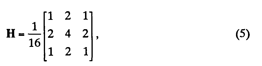
- the average values I i,j '' can be computed as, say, elements of a low-pass-filtered gray-scale image I'' obtained by convolving the intensity with a low-pass kernel H :
- a low-pass kernel H For images whose resolutions are 240 dots per inch (“dpi"), we have used the following low-pass kernel: whereas we have used the following kernel for 600-dpi images:
- the image processor finds locations where there are large brightness changes, as is typically the case at the edge of one of the constituent document images.
- ⁇ 2 x c i , j + ⁇ 2 y c i , j , and
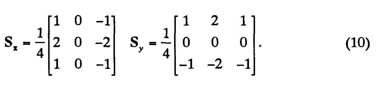
- c i,j is r i,j , g i,j , or b i,j , and S x and S y are horizontal and vertical Sobel kernels with which we convolve the individual color image components.
- Sobel kernels For the 240-dpi case, we have used the following Sobel kernels: For the 600-dpi case, the Sobel kernels we have used are
- steps 30, 32, and 34 as imposing a pixel-qualification criterion, eliminating most of the pixels from consideration and leaving only those with the binary value that identifies them as occupying high-gradient regions.
- Large connected groups of these form the outlines of constituent images, but there typically are many other pixels remaining, and the processor must distinguish between these and those that make up actual constituent-image boundaries.
- One basis for eliminating pixels from consideration is that they do not form large groups of connected pixels.
- Block 38 represents determining the sizes of the remaining connected groups, while block 40 represents eliminating of groups that do not exceed 1,000 pixels each.
- Fig. 3's block 42 represents the step of determining each remaining component's "bounding box" i.e., the smallest rectangle that includes all of that component's pixels and has pixel-row and pixel-column boundaries.
- component 44's bounding box is rectangle 46.
- One of the bounding box's purposes is to provide an easily computed estimate of whether any component is enclosed by another component.
- Such enclosed components can be eliminated from consideration as possible constituent-document boundaries.
- component 48 can be eliminated from consideration because the image region defined by its bounding box 50 falls totally within the region defined by component 44's bounding box 46.
- Fig. 3's block 52 represents the step of removing such enclosed components.
- non-inclusion criterion in the illustrated embodiment because it is relatively convenient, but other types of non-inclusion criteria can be used instead.
- image regions associated with the potentially enclosing and enclosed components do not have to be bounding boxes.
- different, "outer” and “inner” region-defining processes can be used respectively to define the regions associated with the potentially enclosing and enclosed components, and the criterion would be that the inner region defined for a qualifying component cannot be enclosed by the outer region defined for any other component.
- Components that meet the non-inclusion criterion may be subjected to other component-qualification criteria. For example, some components are so shaped that they are unlikely to have arisen from constituent documents' outlines. In Fig. 4, for instance, component 54's bounding box 56 has an aspect ratio that is considerably greater than that which would be expected from any constituent document, so the image processor eliminates that component from consideration, also. Fig. 3's block 58 represents this step.
- the procedure for determining a skew region from a component includes refining the image processor's estimate of the source document's boundary.
- each of the three components 44, 48, and 54 depicted in Fig. 4 has far fewer pixels than the 1,000-pixel minimum.
- a 1000-pixel component's sides are usually much thicker than that of Fig. 4's components.
- the image processor takes advantage of this fact by using a morphological-opening operation to smooth out the component boundary and thereby eliminate further noise-generated pixels.
- Fig. 5 depicts such an operation.
- Its pixel set 62 represents one fragment of a component that has survived the previous elimination operations.
- This pixel set has jagged edges, which would typically represent noise.
- the morphological-opening operation eliminates such noise and thereby refines the estimate of the constituent document's boundary location.
- Such operations can be performed in many ways, but the one that is simplest and illustrates the operation most clearly involves a single "erosion” operation followed by a single “dilation” operation.
- any surviving pixel is eliminated if not all of the eight pixels contiguous to it also survived the previous operations.
- the erosion operation tends to compact the component, eliminating most jagged protrusions. But that operation also shrinks the pixel set, thereby making the component appear smaller than it is in the initial data.
- the image processor performs a "dilation" operation: if a pixel did not previously belong to the component but was contiguous to one that did, it is added to the component.
- the image processor refines the bounding-box determinations by re-computing the bounding boxes from the noise-suppressed components.
- the image processor has finished its assignment of pixels to components. That is, every pixel in the image has been assigned a binary value that indicates whether it belongs to a component ⁇ i.e., whether it has survived the culling processes thus described above ⁇ and those that do belong to components have been labeled with the identities of the components to which they belong.
- the image processor can then begin determining each surviving component's skew angle. It bases that determination on each component's boundary pixels. To identify boundary pixels, the image processor scans the image rightward from the left of the component's bounding box to find the first pixel in each scan line and leftward from the right of the bounding box to find the last pixel in each scan line. It similarly scans from the top and bottom of the bounding box. The pixels thus identified are considered the respective components' boundary pixels.
- Fig. 3's block 70 represents the boundary-determination operation. Occasionally, this operation results in a relatively large number of boundary-identified pixels that are unconnected. The boundary thus determined is considered unreliable in that case, and some remedial operation occurs.
- the unit may repeat the optical scanning and start the whole operation over again, or it may repeat the processing with a different threshold.
- the pixel locations thus determined are the input to the operation for determining the component's skew angle.
- the skew-angle determination which Fig. 3's block 72 represents, employs a two-dimensional-histogram operation.
- Fig. 6 illustrates the principle employed to populate the histogram.
- the upper left corner of an image 74 is conventionally considered the origin of a coordinate system that specifies pixel locations.
- each line can be uniquely represented by an ordered pair ( ⁇ , ⁇ ), where ⁇ is the angle that the line makes with the x axis, and ⁇ is the directed perpendicular distance from that line to the origin, i.e., to the image's upper left corner.
- the two-dimensional histogram has bins for pairs of ( ⁇ , ⁇ ) sub-ranges, where the ⁇ sub-ranges may, say, span the range from the image length to the negative of the image length and the ⁇ sub-range may, say, span the range from, say, -10° to +10°. (Obviously, a more-comprehensive system could have ⁇ extend from -90° to +90°, but such a range is ordinarily unnecessary; users typically orient their documents with only small skew angles.)
- the skew angle is simply determined by noting which-angled bins contain the largest maxima. In practice, the determination is slightly more complicated, since the actual skew angle typically falls between two of the angles for which lines are computed, so the skew-angle determination may be based on adjacent-bin pairs.
- y cos ⁇ has a negative value, so the magnitude of the perpendicular distance ⁇ equals the difference between magnitude of y cos ⁇ and the magnitude of x sin ⁇ .
- skew angle Once the skew angle has been determined by processing the low-resolution image, that angle can be used to de-skew the high-resolution image.
- a memory-efficient way to do this is simply to rotate the contents of each component's bounding box by a de-skewing angle equal to the negative of the skew angle determined for that component. That makes it unnecessary to retain a component-indicating label for each pixel.
- the rotation's equation is as follows: where ( x , y ) is the location of a (high-resolution) input-image pixel, ( x ', y ') is the output-image location that receives the ( x , y ) input pixel's value, ⁇ is the de-skewing angle, and ( x c , y c ) is the center of the bounding box. Then each (high-resolution) pixel within the de-skewed bounding box is assigned a value by reversing the equation (13) operation to find the input-image location that will translate to that output location.
- Fig. 8A shows two components 76 and 78 whose bounding boxes 80 and 82 overlap.
- One way to determine whether the machine can avoid having the user reorient the documents is first to de-skew the (low-resolution) boundary pixels and then compute new bounding boxes on the de-skewed outlines, as Fig. 8B illustrates.
- Fig. 8B shows the new bounding boxes 84 and 86, which we will refer to as the bounding boxes of the output documents ("BBODs") to distinguish them from the original bounding boxes of the input documents ("BBIDs"). If the BBODs turn out not to overlap, the user does not have to re-orient the documents.
- BBODs bounding boxes of the output documents
- the high-resolution image's de-skewing occurs as was just described, with de-skewing values determined for all pixels within a BBID. But if a pixel's transformed location falls outside of a given component's BBOD, it is not used to generate that component's output image.
- the BBOD can be used for other purposes. If there is only a single document on the scanner bed, the document size indicated by the BBOD can be used to select a paper size automatically for copying purposes or to suggest that paper size for the user's approval.
- the output-pixel location typically corresponds to inter-pixel locations in the input image.
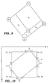
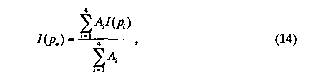
- the image processor To determine the value of an output pixel centered at a point corresponding to Fig. 9's input-image point p o , the image processor begins with the gray-scale values, computed as in equation (1), of the four closest input pixels, whose centers Fig. 9 depicts as being at points p 1, p 2 , p 3 , and p 4 .
- a gray-scale value for p o is determined in accordance with the following equation: where the A i 's are the areas depicted in Fig. 9.
- ⁇ B n B ( p n ) - I ( p n )
- the output pixel receives the value thus imputed to the corresponding input-image point p o.
- determining the value for a pixel at one location in the output image can require input-pixel data drawn from anywhere in the input image. But it may be burdensome to buffer the entire input image in order to compute output-image values. For high-resolution images, such as a 240 dpi image on a A4-size document, the buffer size required to contain the entire image is around 20 megabytes. But the value-computation operation can actually be performed with a considerably smaller buffer if we make the assumption that the skew angle is quite small. This assumption is reasonable, since the user will usually place the constituent documents in rough alignment or can be prompted to do so.
- Fig. 10A illustrates the number of required input lines determined in accordance with the calculation just described.
- row 0 we fill the buffer as Fig. 10A indicates.
- Fig. 10A we put the corresponding input row 0 in the middle buffer row, which is row 4 in this case, with subsequent input rows below it.
- the buffer rows above it, for which there are no corresponding input rows, are filled with white values, i.e., with values (255, 255, 255) in an 8-bit RGB scheme.
- the buffer contains all of the input values needed to compute that first output row's values. (Actually, because rows other than the one that includes the constituent image's center of rotation undergo some translation in addition to the rotation, the number of buffer rows may need to be slightly more than the value indicated above if, as we prefer, the buffered input rows are always to be centered on the output row whose values are being computed.)
- row 0's output values are determined, they are sent to the printer or the next processing operation ⁇ so that, e.g., scanning and printing can be performed concurrently ⁇ and the buffer rows are advanced as Fig. 10B illustrates so that input row 1 is now centered in the buffer. The output row 1 is then computed from these values. This operation continues until the end of the output image is reached.
- this re-orientation operation is but one of a number of processing operations that the image processor performs in order to generate the printer's input.
- Many of those operations such as constituent-image-specific white balancing, contrast enhancement, and thresholding, employ parameterized functions that depend on various of a constituent document's global features such as average brightness, brightness variation, average saturation, etc.
- the data for these parameters is taken most economically from a "preview,” low-resolution version of the image such as the one used as described above to identify components and determine their skew angles. That is, the parameter determination should be performed before conversion to the high-resolution de-skewed image. But the parameters should be based on the individual constituent documents rather than on the total image.
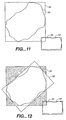
- SBBOD slanted bounding box of the output document
- Fig. 12 depicts.
- the SBBOD is the rectangle that results from skewing the BBOD by the associated component's skew angle.
- statistics are taken only from pixels that fall within the intersection of the component's SBBOD 98 and its BBID 92. That is, the statistics for a component 90 are taken from those pixels within the BBID that are not within Fig. 12's shaded regions.
- intersection point a is determined by substituting x 1 into equation (17)
- intersection points b and c are determined by substituting y 1 into equations (17) and (18), respectively, and the other intersection points d, e, f, g , and h are similarly determined.
- each pixel whose y coordinate is less than that of intersection point a and whose x coordinate is less than that of intersection point b has its coordinates substituted into the equation for line
- each remaining pixel whose x coordinate is greater than intersection point f 's and whose y coordinate exceeds intersection point e 's has its coordinates substituted into line
- the present invention provides a way of easily avoiding the disordered appearance that has heretofore afflicted multiple-document images. It thus constitutes a significant advance in the art.
Landscapes
- Engineering & Computer Science (AREA)
- Multimedia (AREA)
- Signal Processing (AREA)
- Image Processing (AREA)
- Editing Of Facsimile Originals (AREA)
Abstract
Description





Claims (10)
- A method of generating a composite output image by separately de-skewing constituent skew regions of a composite input image, the method comprising the steps of:A) receiving electrical input signals representing the composite input image;B) providing a preview version of the composite input image, which preview version consists of a plurality of preview pixels;C) identifying as qualifying pixels the preview pixels that meet a set of at least one predetermined pixel-qualification criterion;D) identifying as components connected groups of the qualifying pixels;E) identifying as qualifying components the components that meet a set of at least one predetermined component-qualification criterion;F) determining a skew region of the composite input image from each qualifying component in accordance with a skew-region procedure;G) associating a respective de-skew angle with each skew region, the de-skew angle associated with at least one skew region differing from the de-skew angle associated with at least one other skew region;H) producing as the composite output image an image that includes a respective constituent output sub-image generated from each skew region of the composite input image by rotating that skew region by its de-skew angle; andI) generating electrical signals that represent the composite output image.
- A method as defined in claim 1 wherein one said component-qualification criterion is that, for a given component to be a qualifying component, the region of the composite input image defined in accordance with an inner-region procedure from the given component cannot be contained within the region of the composite input image defined in accordance with an outer-region procedure from any other component.
- A method as defined in claim 2 wherein the inner- and outer-region procedures are the same.
- A photocopier comprising:A) a scanner that optically scans an input region and generates electrical scanner signals representing an image of the input region;B) image-processing circuitry that performs a sequence of at least one image-revision step, in which sequence each image-revision step receives a respective input-image version consisting of input pixels and produces therefrom an output image version consisting of output pixels, the input image version of the first image-revision step is the image represented by the scanner signals, the input image version of any subsequent image-revision step is the output image version of the preceding image-revision step, and one of the image-revision steps is a de-skewing operation whose input image is denominated a composite input image and comprises the steps of:i) providing a preview version of a composite input image, which preview version consists of a plurality of preview pixels;ii) identifying as qualifying pixels the preview pixels that meet a set of at least one predetermined pixel-qualification criterion;iii) identifying as components connected groups of the qualifying pixels;iv) identifying as qualifying components the components that meet a set of at least one predetermined component-qualification criterion;v) determining a skew region of the composite input image from each qualifying component in accordance with a skew-region procedure;vi) associating a respective de-skew angle with each skew region, at least one de-skew angle differing from at least one other de-skew angle;vii) producing as the de-skewing operation's output image a composite output image that includes a constituent output sub-image respectively generated from each skew region of the composite input image by rotating that skew region by its de-skew angle; andviii) generating electrical signals that represent the composite output image; andC) a printer that prints the image that the output image version of the last image-revision step represents.
- A photocopier as defined in claim 4 wherein one said component-qualification criterion is that, for a given component to be a qualifying component, the region of the composite input image defined in accordance with an inner-region procedure from the given component cannot be contained within the region of the composite input image defined in accordance with an outer-region procedure from any other component.
- A photocopier as defined in claim 5 wherein the inner- and outer-region procedures are the same.
- A computer-program of instructions for execution by a computer to perform a method of generating a composite output image by separately de-skewing constituent skew regions of a composite input image, the method comprising the steps of:A) receiving electrical input signals representing a composite input image that includes constituent skew regions;B) providing a preview version of the composite input image, which preview version consists of a plurality of preview pixels;C) identifying as qualifying pixels the preview pixels that meet a set of at least one predetermined pixel-qualification criterion;D) identifying as components connected groups of the qualifying pixels;E) identifying as qualifying components the components that meet a set of at least one predetermined component-qualification criterion;F) determining a skew region of the composite input image from each qualifying component in accordance with a skew-region procedure;G) associating a respective de-skew angle with each skew region, the de-skew angle associated with at least one skew region differing from the de-skew angle associated with at least one other skew region;H) producing as a composite output image an image that includes a respective constituent output sub-image generated from each skew region of the composite input image by rotating that skew region by its de-skew angle; andI) generating electrical signals that represent the composite output image.
- A computer-program as defined in claim 7 wherein one said component-qualification criterion is that, for a given component to be a qualifying component, the region of the composite input image defined in accordance with an inner-region procedure from the given component cannot be contained within the region of the composite input image defined in accordance with an outer-region procedure from any other component.
- A computer-program as defined in claim 8 wherein the inner- and outer-region procedures are the same.
- A computer-readable medium comprising the computer-program as defined in any one of claims 7 to 9.
Applications Claiming Priority (2)
| Application Number | Priority Date | Filing Date | Title |
|---|---|---|---|
| US244916 | 1988-09-14 | ||
| US09/244,916 US6373590B1 (en) | 1999-02-04 | 1999-02-04 | Method and apparatus for slant adjustment and photo layout |
Publications (2)
| Publication Number | Publication Date |
|---|---|
| EP1026877A2 true EP1026877A2 (en) | 2000-08-09 |
| EP1026877A3 EP1026877A3 (en) | 2001-12-12 |
Family
ID=22924603
Family Applications (1)
| Application Number | Title | Priority Date | Filing Date |
|---|---|---|---|
| EP00300707A Withdrawn EP1026877A3 (en) | 1999-02-04 | 2000-01-31 | Method, apparatus, program and medium for slant adjustment and photo layout |
Country Status (3)
| Country | Link |
|---|---|
| US (1) | US6373590B1 (en) |
| EP (1) | EP1026877A3 (en) |
| JP (1) | JP2000228722A (en) |
Cited By (1)
| Publication number | Priority date | Publication date | Assignee | Title |
|---|---|---|---|---|
| US7423671B2 (en) * | 2002-10-31 | 2008-09-09 | Casio Computer Co., Ltd. | Image pickup apparatus and photographing method with image angle correction for combining image data |
Families Citing this family (32)
| Publication number | Priority date | Publication date | Assignee | Title |
|---|---|---|---|---|
| US7411593B2 (en) * | 2001-03-28 | 2008-08-12 | International Business Machines Corporation | Image rotation with substantially no aliasing error |
| JP2003259110A (en) * | 2002-02-28 | 2003-09-12 | Fujitsu Ltd | Image combining device, its method, and program |
| US7068855B2 (en) * | 2002-07-16 | 2006-06-27 | Hewlett-Packard Development Company, L.P. | System and method for manipulating a skewed digital image |
| TWI267800B (en) * | 2003-06-13 | 2006-12-01 | Lite On Technology Corp | Automatic correction method of tilted image |
| JP4363151B2 (en) * | 2003-10-14 | 2009-11-11 | カシオ計算機株式会社 | Imaging apparatus, image processing method thereof, and program |
| US7356200B2 (en) * | 2003-11-03 | 2008-04-08 | Hewlett-Packard Development Company, L.P. | Method and device for determining skew angle of an image |
| JP4238749B2 (en) * | 2004-03-10 | 2009-03-18 | カシオ計算機株式会社 | Image processing apparatus, image projection apparatus, image processing method, and program |
| JP2005267457A (en) * | 2004-03-19 | 2005-09-29 | Casio Comput Co Ltd | Image processing apparatus, photographing apparatus, image processing method, and program |
| US8320708B2 (en) * | 2004-04-02 | 2012-11-27 | K-Nfb Reading Technology, Inc. | Tilt adjustment for optical character recognition in portable reading machine |
| JP4574235B2 (en) * | 2004-06-04 | 2010-11-04 | キヤノン株式会社 | Image processing apparatus, control method therefor, and program |
| JP4402540B2 (en) * | 2004-08-06 | 2010-01-20 | キヤノン株式会社 | Image processing system, control method therefor, and program |
| US7623734B2 (en) * | 2004-09-30 | 2009-11-24 | Microsoft Corporation | Method and system for automatically inscribing noisy objects in scanned image data within a minimum area rectangle |
| US20060098243A1 (en) * | 2004-11-08 | 2006-05-11 | Lexmark International, Inc. | Determining a gray background value and/or skew of a scanned document |
| US7483589B2 (en) * | 2004-12-07 | 2009-01-27 | Lexmark International, Inc. | Method for copying objects |
| US20070002375A1 (en) * | 2005-06-30 | 2007-01-04 | Lexmark International, Inc. | Segmenting and aligning a plurality of cards in a multi-card image |
| WO2007027893A2 (en) * | 2005-08-30 | 2007-03-08 | The Regents Of The University Of California, Santa Cruz | Kernel regression for image processing and reconstruction |
| JP4574503B2 (en) * | 2005-09-09 | 2010-11-04 | キヤノン株式会社 | Image processing apparatus, image processing method, and program |
| DE112006002940T5 (en) | 2005-11-05 | 2008-12-11 | 3M Innovative Properties Co., St. Paul | Optical films comprising high refractive index and antireflective coatings |
| JP2008059081A (en) * | 2006-08-29 | 2008-03-13 | Sony Corp | Image processing apparatus, image processing method, and computer program |
| US8120810B2 (en) * | 2007-08-10 | 2012-02-21 | International Business Machines Corporation | Method and system for adjusting scanned images |
| JP5002497B2 (en) * | 2008-03-11 | 2012-08-15 | 株式会社Pfu | Image processing apparatus, image processing method, and image processing program |
| US8064729B2 (en) * | 2008-04-03 | 2011-11-22 | Seiko Epson Corporation | Image skew detection apparatus and methods |
| US9547799B2 (en) * | 2008-07-17 | 2017-01-17 | Sharp Laboratories Of America, Inc. | Methods and systems for content-boundary detection |
| JP5253035B2 (en) * | 2008-08-08 | 2013-07-31 | キヤノン株式会社 | Image processing apparatus, image processing method, and program |
| US8406500B2 (en) * | 2009-03-03 | 2013-03-26 | Seiko Epson Corporation | Simultaneously scanning multiple checks |
| US8913285B1 (en) * | 2009-06-07 | 2014-12-16 | Apple Inc. | Automated method of decomposing scanned documents |
| US8873864B2 (en) * | 2009-12-16 | 2014-10-28 | Sharp Laboratories Of America, Inc. | Methods and systems for automatic content-boundary detection |
| CN103119624A (en) * | 2010-07-29 | 2013-05-22 | 惠普发展公司,有限责任合伙企业 | Insert content and quarantines into pages |
| CN103917376B (en) * | 2011-07-05 | 2016-12-21 | 惠普工业印刷有限公司 | Printers and Printing Methods |
| US10091391B2 (en) * | 2015-11-10 | 2018-10-02 | Bidirectional Display, Inc. | System and method for constructing document image from snapshots taken by image sensor panel |
| JP6957889B2 (en) * | 2017-02-08 | 2021-11-02 | 富士フイルムビジネスイノベーション株式会社 | Image processing device and image processing program |
| WO2023069445A1 (en) * | 2021-10-18 | 2023-04-27 | Google Llc | User input based distraction removal in media items |
Family Cites Families (10)
| Publication number | Priority date | Publication date | Assignee | Title |
|---|---|---|---|---|
| FR2550403A1 (en) * | 1983-08-04 | 1985-02-08 | Thomson Csf | METHOD FOR DISCRIMINATING CONTOURS AND TEXTURES IN A VIDEO IMAGE AND CONTOUR DETECTOR DEVICE FOR IMPLEMENTING SAID METHOD |
| US5103490A (en) | 1990-06-13 | 1992-04-07 | National Computer Systems, Inc. | Method and apparatus for storing and merging multiple optically scanned images |
| US5465163A (en) | 1991-03-18 | 1995-11-07 | Canon Kabushiki Kaisha | Image processing method and apparatus for processing oversized original images and for synthesizing multiple images |
| US5430550A (en) | 1991-06-14 | 1995-07-04 | Minolta Camera Kabushiki Kaisha | Image reading apparatus which corrects for positional and angular deviation between the image sensor and the document |
| JP2989364B2 (en) | 1992-03-12 | 1999-12-13 | シャープ株式会社 | Image processing apparatus and image processing method |
| US5440403A (en) | 1992-07-24 | 1995-08-08 | Minolta Camera Kabushiki Kaisha | Image reading means for reading a document including a plurality of images and space |
| US5685002A (en) | 1993-09-29 | 1997-11-04 | Minolta Co., Ltd. | Image processing system capable of generating a multi-picture image |
| US5649032A (en) | 1994-11-14 | 1997-07-15 | David Sarnoff Research Center, Inc. | System for automatically aligning images to form a mosaic image |
| JPH08237407A (en) | 1994-12-09 | 1996-09-13 | Xerox Corp | Method of positioning relative alignment of picture tile andcorrecting penetrative distortion |
| US6188779B1 (en) * | 1998-12-30 | 2001-02-13 | L&H Applications Usa, Inc. | Dual page mode detection |
-
1999
- 1999-02-04 US US09/244,916 patent/US6373590B1/en not_active Expired - Lifetime
-
2000
- 2000-01-31 EP EP00300707A patent/EP1026877A3/en not_active Withdrawn
- 2000-02-03 JP JP2000026724A patent/JP2000228722A/en not_active Withdrawn
Cited By (1)
| Publication number | Priority date | Publication date | Assignee | Title |
|---|---|---|---|---|
| US7423671B2 (en) * | 2002-10-31 | 2008-09-09 | Casio Computer Co., Ltd. | Image pickup apparatus and photographing method with image angle correction for combining image data |
Also Published As
| Publication number | Publication date |
|---|---|
| JP2000228722A (en) | 2000-08-15 |
| EP1026877A3 (en) | 2001-12-12 |
| US6373590B1 (en) | 2002-04-16 |
Similar Documents
| Publication | Publication Date | Title |
|---|---|---|
| US6373590B1 (en) | Method and apparatus for slant adjustment and photo layout | |
| EP0803842B1 (en) | Binary image forming device | |
| EP2149860B1 (en) | Image processing unit, noise reduction method, program, and storage medium | |
| US5568571A (en) | Image enhancement system | |
| US4924521A (en) | Image processing system and method employing combined black and white and gray scale image data | |
| US20160050338A1 (en) | Skew detection | |
| EP1178668B1 (en) | Digital imaging device with background training | |
| US20110025860A1 (en) | Image output apparatus, captured image processing system, and recording medium | |
| US7242816B2 (en) | Group average filter algorithm for digital image processing | |
| EP0982929A3 (en) | Image processing device | |
| US6721458B1 (en) | Artifact reduction using adaptive nonlinear filters | |
| JPH118755A (en) | Method for scanning and detecting many photographs and removing artificial edge | |
| US7350710B2 (en) | Two-dimensional code extracting method | |
| US5483606A (en) | Method for automatically registering a document having a plurality of pages | |
| US6501565B1 (en) | Method and apparatus for smoothing text outlines | |
| CN101320425A (en) | Image processing device and method, image forming device, image processing system | |
| US6271935B1 (en) | Method to remove edge artifacts from skewed originals | |
| US20020176120A1 (en) | Photo extraction techniques | |
| US20100091037A1 (en) | Image rotation | |
| US7724981B2 (en) | Adaptive contrast control systems and methods | |
| EP0870276B1 (en) | A method for transforming a gray-level image into a black-and-white image | |
| JP3142279B2 (en) | Halftone dot area separation device | |
| US20090016613A1 (en) | Image processing apparatus, image processing method, and computer program product | |
| KR100260923B1 (en) | Local binarization apparatus and method for burns | |
| JPH1098613A (en) | Image processing device |
Legal Events
| Date | Code | Title | Description |
|---|---|---|---|
| PUAI | Public reference made under article 153(3) epc to a published international application that has entered the european phase |
Free format text: ORIGINAL CODE: 0009012 |
|
| AK | Designated contracting states |
Kind code of ref document: A2 Designated state(s): AT BE CH CY DE DK ES FI FR GB GR IE IT LI LU MC NL PT SE |
|
| AX | Request for extension of the european patent |
Free format text: AL;LT;LV;MK;RO;SI |
|
| PUAL | Search report despatched |
Free format text: ORIGINAL CODE: 0009013 |
|
| AK | Designated contracting states |
Kind code of ref document: A3 Designated state(s): AT BE CH CY DE DK ES FI FR GB GR IE IT LI LU MC NL PT SE |
|
| AX | Request for extension of the european patent |
Free format text: AL;LT;LV;MK;RO;SI |
|
| RIC1 | Information provided on ipc code assigned before grant |
Free format text: 7H 04N 1/387 A, 7G 06T 5/00 B |
|
| AKX | Designation fees paid | ||
| REG | Reference to a national code |
Ref country code: DE Ref legal event code: 8566 |
|
| STAA | Information on the status of an ep patent application or granted ep patent |
Free format text: STATUS: THE APPLICATION IS DEEMED TO BE WITHDRAWN |
|
| 18D | Application deemed to be withdrawn |
Effective date: 20020613 |