EP1026783A2 - Improved branching connector and electrical connector box assembly - Google Patents
Improved branching connector and electrical connector box assembly Download PDFInfo
- Publication number
- EP1026783A2 EP1026783A2 EP00101953A EP00101953A EP1026783A2 EP 1026783 A2 EP1026783 A2 EP 1026783A2 EP 00101953 A EP00101953 A EP 00101953A EP 00101953 A EP00101953 A EP 00101953A EP 1026783 A2 EP1026783 A2 EP 1026783A2
- Authority
- EP
- European Patent Office
- Prior art keywords
- connector
- terminal supports
- circuit
- circuit unit
- extension
- Prior art date
- Legal status (The legal status is an assumption and is not a legal conclusion. Google has not performed a legal analysis and makes no representation as to the accuracy of the status listed.)
- Withdrawn
Links
- 238000003780 insertion Methods 0.000 claims abstract description 37
- 230000037431 insertion Effects 0.000 claims abstract description 37
- 238000011179 visual inspection Methods 0.000 claims description 2
- 238000012790 confirmation Methods 0.000 abstract description 2
- 230000000007 visual effect Effects 0.000 abstract 1
- 229920003002 synthetic resin Polymers 0.000 description 4
- 239000000057 synthetic resin Substances 0.000 description 4
- 238000000465 moulding Methods 0.000 description 2
- 238000007689 inspection Methods 0.000 description 1
- 238000003466 welding Methods 0.000 description 1
Images


Classifications
-
- H—ELECTRICITY
- H01—ELECTRIC ELEMENTS
- H01R—ELECTRICALLY-CONDUCTIVE CONNECTIONS; STRUCTURAL ASSOCIATIONS OF A PLURALITY OF MUTUALLY-INSULATED ELECTRICAL CONNECTING ELEMENTS; COUPLING DEVICES; CURRENT COLLECTORS
- H01R9/00—Structural associations of a plurality of mutually-insulated electrical connecting elements, e.g. terminal strips or terminal blocks; Terminals or binding posts mounted upon a base or in a case; Bases therefor
- H01R9/22—Bases, e.g. strip, block, panel
- H01R9/24—Terminal blocks
-
- Y—GENERAL TAGGING OF NEW TECHNOLOGICAL DEVELOPMENTS; GENERAL TAGGING OF CROSS-SECTIONAL TECHNOLOGIES SPANNING OVER SEVERAL SECTIONS OF THE IPC; TECHNICAL SUBJECTS COVERED BY FORMER USPC CROSS-REFERENCE ART COLLECTIONS [XRACs] AND DIGESTS
- Y10—TECHNICAL SUBJECTS COVERED BY FORMER USPC
- Y10S—TECHNICAL SUBJECTS COVERED BY FORMER USPC CROSS-REFERENCE ART COLLECTIONS [XRACs] AND DIGESTS
- Y10S439/00—Electrical connectors
- Y10S439/949—Junction box with busbar for plug-socket type interconnection with receptacle
Definitions
- the present invention relates to a branching connector having a circuit unit and a connector for a wire harness and to an electrical connection box which houses the branching connector.
- An electrical connection box houses a branching connector, on which a plurality of relays, fuses, and the like are mounted and to which wire harnesses, coming in from outside, are connected.
- the branching connector houses a circuit unit from which a plurality of connector terminals project, both above and below the outer surface of the circuit unit. These connector terminals also project through the upper case of the branching connector to connect fuses, relays and the like and into the lower case of the branching connector.
- the circuit unit is formed by stacking a plurality of circuit boards, one on top of the other. Circuits are formed from a plurality of bus bars, which make up the circuit board, and the connector terminals extend from the bus bars.
- the inner surface of the branching connector abuts the upper surface of the circuit unit and the connector terminals project through the upper case of the branching connector.
- the individual connector terminals are positioned in and can form, for example, relay cavities, fuse cavities, or connector mounting openings. These fuse cavities, relay cavities and connector mounting openings are generally part of the upper case into which the fuses and connectors are positioned.
- the circuit unit When assembling the branching connector, the circuit unit is positioned inside an upper case and a lower case, and the upper and lower cases are connected and fixed to each other by pairs of elastic engagement pieces disposed on each of the cases. If the branching connector is assembled so that the upper surface and the lower surface of the circuit unit do not tightly abut the inner surfaces of the upper case and the lower case, the connector terminals will not project a predetermined length through the case. As a result, the relays, fuses, and the like will not be reliably connected to the connector terminals.
- a tool When assembling the branching connector, a tool is used to apply a predetermined load to cause the elastic engagement pieces on the cases to connect. Since it is not possible to confirm whether the upper case, the lower case, and the circuit unit are properly aligned before connecting the two cases, it must be assumed that the circuit unit and the upper and lower cases are aligned when the elastic engagement pieces are aligned and the tool connects the upper and lower cases. Furthermore, since the elastic engagement pieces are disposed on the sides of the cases, it is not possible to confirm whether the central portions of the circuit unit are properly positioned in the casing, even when the elastic engagement pieces are engaged. There is thus a need to provide a branching connector wherein the circuit unit and the upper and lower cases can be properly assembled in a reliable manner.
- the present invention accomplishes this by providing an extension on the circuit unit which extends through the upper case and aligns with a corresponding hole in the upper case.
- the extension has a top surface that is substantially flat and coplanar with the outer surface of the upper case. With this coplanar arrangement, proper assembly can be visually confirmed, either by the human eye or by a conventional inspection machine. Furthermore, since the extension is preferably positioned in close association with the connector terminals, the extension also allows for confirmation that the central portions of the circuit unit tightly abut the upper case.
- coplanar means that the top surface of the extension is in the same plane as at least a portion of the outer surface of the upper case.
- the present invention is a branching connector comprising a casing in which a circuit unit is housed, wherein the circuit unit is a plurality of stacked circuit boards on which bus bars form circuits; connecting terminals extend from the circuit boards and project from the surface of the circuit unit in the direction in which the circuit boards are stacked; the connecting terminals project through the outer surface of the casing to form connectors for electronic members; one or more extensions are disposed on the circuit boards, the extensions extending from the surface of the circuit unit in stacking direction; and insertion openings are disposed on the casing to allow for insertion of the extensions therethrough, the relative heights of the extensions and the insertion openings being such that the top of each extension is coplanar with a portion of the outer surface of the casing at the insertion opening to provide for visual inspection from the front of the branching connector and thereby confirm proper assembly.
- the extensions are terminal supports formed integrally with one or more of the circuit boards through which the connecting terminals are inserted, the terminal supports supporting the connecting terminals so that they are perpendicular to the circuit board.
- the terminal supports are formed integrally with the uppermost circuit board, i.e. the circuit board that forms the upper surface of the circuit unit.
- the extensions extend through the casing at a point where the inner surface of the casing abuts the upper surface of the circuit unit, and even more preferably, where there is a connector mount opening.
- the electrical connection box according to the present invention includes a branching connector as described herein.
- the extension when a connector mounting opening is integrated with the upper casing of the branching connector, the extension extends from the surface of the circuit unit and into the insertion opening of the connector mounting opening.
- the extension can be: (1) a terminal support disposed integrally with a circuit board to provide perpendicular support for a connector terminal; (2) an extension disposed integrally with the circuit board and not associated with the connector terminal; or (3) an extension extending from the bus bar itself.
- the extension can extend, for example, from a surface on one side of the circuit unit, relative to the direction in which the bodies are stacked.
- electrical connection box 10 is formed from branching connector 11, upper cover 12, and lower cover 13.
- Branching connector 11 is formed from upper connector 16 and lower connector 17.
- Fuses 14 and connectors 15 are mounted on upper connector 16.
- External connectors (not shown) connect a wire harness W to lower connector 17.
- Fuses 14 and connector 15 are covered by upper cover 12.
- Lower cover 13 covers the external connectors of lower connector 17.
- Lower cover 13 is formed so that the wire harness W can be passed through, as shown.
- Upper cover 12 and lower cover 13 are connected to each other, with branching connector 11 housed inside, by elastic engagement pieces 18 (only one is shown in Fig. 3), which are formed integrally with upper cover 12, and engagement pieces 19, which are formed integrally with lower cover 13.
- Fig. 4 shows branching connector 11 in a disassembled state.
- Branching connector 11 includes circuit unit 20, upper case 21, and lower case 22.
- upper case 21 and lower case 22 form the upper and lower connectors.
- Circuit unit 20 is formed by stacking a plurality of circuit boards 24a-24e. Circuits are formed on circuit boards 24a-24e by a plurality of bus bars 23. Circuit boards 24a-24e are formed from insulative synthetic resin, and the plurality of bus bars 23 are arranged on the upper surfaces thereof. Extending from bus bars 23 are connector terminals 25, 26. Connector terminals 25, 26 extend upward and downward, perpendicular to circuit boards 24a-24e. Connector terminals 25, 26 of bus bars 23 are inserted through circuit boards 24a-24e and project from the upper surface of uppermost circuit board 24a and from the lower surface of lowermost circuit board 24e. On the circuit board 24e, at the lowermost position of the circuit unit 20, bus bars 23 are also disposed on the lower surface, forming circuits.
- upper surface 20a of circuit unit 20 is formed from the circuits of uppermost circuit board 24a, and lower surface 20b is similarly formed from the circuits on the lower surface of lowermost circuit board 24e.
- upper surface 20a and lower surface 20b of circuit unit 20 are circuit surfaces.
- Upper case 21 is formed integrally from synthetic resin and includes connector mounting openings 27 and fuse cavities 28, which serve as upper connector 16.
- Connector terminals 25 are disposed in connector mounting openings 27, and connector terminals 26 are disposed in fuse cavities 28.
- Lower case 22 is also formed integrally from a synthetic resin and includes connector mounting openings (not shown), which serve as lower connector 17 of circuit unit 20.
- Upper case 21 and lower case 22 are connected to each other so that they abut upper surface 20a and lower surface 20b respectively.
- elastic engagement pieces 29, which are formed integrally with the side surfaces of upper case 21 engage engagement pieces 30, which are formed integrally with the side surfaces of lower case 22, thus connecting cases 21 and 22 to each other.
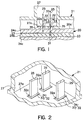
- Fig. 1 is a schematic vertical cross-section showing one of connector mounting openings 27 disposed on upper case 21 and sections of circuit boards 24a, 24b, 24c, which serve as the upper portion of circuit unit 20.
- Connector terminals 25 extend from bus bars 23, which serve as the circuits on circuit boards 24a-24e, and have a width greater than the thickness of the boards.
- One of connector terminals 25 extends from bus bar 23 on circuit board 24c and passes through insertion opening 31 disposed on circuit board 24b.
- Connector terminals 25 project a predetermined length above upper surface 20a.
- Insertion opening 31 is formed with a width slightly greater than that of connector terminals 25 and with a thickness slightly greater than that of connector terminals 25. This is done to take into account dimension tolerances in the circuit boards 24a-24e, which are formed by molding synthetic resin, as well as tolerances in assembly, thus allowing easier assembly.
- terminal supports 32 are formed integrally as extensions on circuit board 24a.
- Each terminal support 32 includes an extension 33 formed on the upper surface of circuit board 24a and a support opening 34 formed in the center of extension 33. The size of support opening 34 is such that connector terminal 25 can be pressed through.
- terminal supports 32 are formed so that they can support connector terminals 25 perpendicularly relative to circuit board 24a.
- Terminal supports 32 are inserted through insertion openings 35. Insertion openings 35 allow for molding tolerances in upper case 21 and circuit boards 24a-24e as well as assembly tolerances. To make assembly easier, insertion openings 35 are formed larger than the horizontal cross section of extensions 33. Terminal supports 32 are formed so that when the inner surface of upper case 21 is tightly abutted against upper surface 20a of circuit unit 20, each upper end surface 32a of terminal supports 32 is at the same height as bottom surface 27a of connector mounting opening 27, i.e. surfaces 32a and 27a are coplanar.
- terminal supports 32 formed integrally with circuit board 24e disposed at the lowermost position of circuit unit 20. Terminal supports 32 are inserted into insertion openings 35 disposed in connector mounting openings 27 at the corresponding positions.
- circuit unit 20 is assembled with upper case 21 so that the inner surface of upper case 21 abuts upper surface 20a of circuit unit 20.
- This causes terminal supports 32, through which connector terminals 25 are inserted, to be inserted into insertion openings 35 of connector mounting openings 27.
- terminal supports 32 through which connector terminals 25 are inserted, to be inserted into insertion openings 35 of connector mounting openings 27.
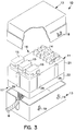
- FIG. 2 when circuit unit 20 and upper case 21 are assembled together, it is possible to look from the front of upper case 21 to visually inspect the relative heights (along the direction in which circuit unit 20 and upper case 21 are stacked) of terminal supports 32 and insertion openings 35, i.e. the relative heights of upper surface 32a and bottom surface 27a.
- terminal supports 32 can be minimized since terminal supports 32 are formed integrally with circuit board 24a, which is closest to upper case 21. As a result, when circuit unit 20 and upper case 21 are assembled with proper alignment, the relative heights of terminal supports 32 and insertion openings 35 are not significantly affected by variations in the lengths of terminal supports 32. This allows the relative heights of terminal supports 32 and insertion openings 35 to effectively reflect the state of the assembly, which can then be visually evaluated.
- circuit unit 20 and lower case 22 are assembled can be evaluated directly from terminal supports 32, which are disposed on lower surface 20b and which extend through insertion openings disposed on lower connector 17.
- circuit unit 20 and upper case 21, as well as circuit unit 20 and lower case 22, are properly assembled, elastic engagement pieces 29 of upper case 21 are engaged with engagement pieces 30 of lower case 22, thus integrating upper case 21 and lower case 22 in a properly assembled state.
- terminal support 40 is formed integrally with circuit board 24b on the side from which connector terminals 25 extend. Terminal support 40 extends through insertion opening 35 of upper case 21, through which connector terminal 25 is inserted. The relative heights of terminal support 40 and insertion opening 35 can be checked from the front of upper case 21.
- extension 41 is formed integrally with circuit board 24a. Extension 41 extends in the direction in which the circuit boards are stacked and is disposed at a position where no connector terminal 25 is inserted. Upper case 21 is formed with insertion opening 42, through which extension 41 is inserted. As shown in Fig. 6, the upper end of extension 41 can be lower than the upper opening of insertion opening 42 or can be at the same position. The relative heights of extension 41 and insertion opening 42 are checked from the front of upper case 21.
- extension 44 does not have to be formed integrally with a circuit board. Instead, extension 44 extends along the direction in which the circuit boards are stacked and is formed integrally with a bus bar, as is the case with the connector terminals.
- Terminal supports 32 do not have to project into the connector mounting openings 27. It would also be possible to have terminal supports 32 project into cavities such as fuse cavities 28 or relay cavities or at some other point on the case.
- the extensions disposed on circuit board 24a or bus bars 23 do not have to be inserted into insertion openings disposed at the bottom of cavities in the case, such as connector mounting openings 27, fuse cavities 28, or relay cavities. It would also be possible to have insertion openings disposed at positions where no opening 27 or cavity 28 is formed. In this case, the relative heights of the extensions and the insertion openings can be easily inspected visually from the front of the case. This makes it possible to easily check the manner in which the case is assembled.
- the extension does not have to be integrally formed with circuit boards 24a-24e or bus bars 23. It would also be possible to have the extension bonded, e.g. through adhesion or welding, to circuit boards 24a-24e or to bus bars 23, as shown in Fig. 8 with extension 46 extending from circuit board 24a through insertion opening 48.
- the branching connector can be implemented so that the connector on which connector mounting openings are formed for connection of external connectors is disposed on the same surface as the connector to which electronic parts are connected.
Landscapes
- Connection Or Junction Boxes (AREA)
- Coupling Device And Connection With Printed Circuit (AREA)
Abstract
Connection terminals 25 extending from bus bars 23 are
projected from an upper case 21. A circuit board 24a closest to
the upper case 21 is formed integrally with terminal supports 32
supporting the connection terminals 25 perpendicularly on the
circuit board 24a. Insertion openings 35 are formed at the
bottom of connector mounting openings 27 through which the
connection terminals 25 project. The terminal supports 32
supporting the connection terminals 25 are inserted through the
insertion openings 35. The terminal supports 32 and the
insertion openings 35 are disposed so that, when an inner side
surface of the upper case 21 abuts the upper surface of a circuit
unit 20 and the two are assembled with proper alignment, upper
end surfaces 32a of the terminal supports 32 are coplanar with a
bottom surface 27a on which are disposed the insertion openings
35, thereby allowing for visual confirmation of proper alignment.
Description
- The present invention relates to a branching connector having a circuit unit and a connector for a wire harness and to an electrical connection box which houses the branching connector.
- Conventionally, automobiles use electrical connection boxes, such as relay boxes and fuse boxes. An electrical connection box houses a branching connector, on which a plurality of relays, fuses, and the like are mounted and to which wire harnesses, coming in from outside, are connected. The branching connector houses a circuit unit from which a plurality of connector terminals project, both above and below the outer surface of the circuit unit. These connector terminals also project through the upper case of the branching connector to connect fuses, relays and the like and into the lower case of the branching connector. The circuit unit is formed by stacking a plurality of circuit boards, one on top of the other. Circuits are formed from a plurality of bus bars, which make up the circuit board, and the connector terminals extend from the bus bars.
- Generally, the inner surface of the branching connector abuts the upper surface of the circuit unit and the connector terminals project through the upper case of the branching connector. The individual connector terminals are positioned in and can form, for example, relay cavities, fuse cavities, or connector mounting openings. These fuse cavities, relay cavities and connector mounting openings are generally part of the upper case into which the fuses and connectors are positioned.
- When assembling the branching connector, the circuit unit is positioned inside an upper case and a lower case, and the upper and lower cases are connected and fixed to each other by pairs of elastic engagement pieces disposed on each of the cases. If the branching connector is assembled so that the upper surface and the lower surface of the circuit unit do not tightly abut the inner surfaces of the upper case and the lower case, the connector terminals will not project a predetermined length through the case. As a result, the relays, fuses, and the like will not be reliably connected to the connector terminals.
- When assembling the branching connector, a tool is used to apply a predetermined load to cause the elastic engagement pieces on the cases to connect. Since it is not possible to confirm whether the upper case, the lower case, and the circuit unit are properly aligned before connecting the two cases, it must be assumed that the circuit unit and the upper and lower cases are aligned when the elastic engagement pieces are aligned and the tool connects the upper and lower cases. Furthermore, since the elastic engagement pieces are disposed on the sides of the cases, it is not possible to confirm whether the central portions of the circuit unit are properly positioned in the casing, even when the elastic engagement pieces are engaged. There is thus a need to provide a branching connector wherein the circuit unit and the upper and lower cases can be properly assembled in a reliable manner.
- The present invention accomplishes this by providing an extension on the circuit unit which extends through the upper case and aligns with a corresponding hole in the upper case. The extension has a top surface that is substantially flat and coplanar with the outer surface of the upper case. With this coplanar arrangement, proper assembly can be visually confirmed, either by the human eye or by a conventional inspection machine. Furthermore, since the extension is preferably positioned in close association with the connector terminals, the extension also allows for confirmation that the central portions of the circuit unit tightly abut the upper case.
- As used herein, the term coplanar means that the top surface of the extension is in the same plane as at least a portion of the outer surface of the upper case.
- Broadly, the present invention is a branching connector comprising a casing in which a circuit unit is housed, wherein the circuit unit is a plurality of stacked circuit boards on which bus bars form circuits; connecting terminals extend from the circuit boards and project from the surface of the circuit unit in the direction in which the circuit boards are stacked; the connecting terminals project through the outer surface of the casing to form connectors for electronic members; one or more extensions are disposed on the circuit boards, the extensions extending from the surface of the circuit unit in stacking direction; and insertion openings are disposed on the casing to allow for insertion of the extensions therethrough, the relative heights of the extensions and the insertion openings being such that the top of each extension is coplanar with a portion of the outer surface of the casing at the insertion opening to provide for visual inspection from the front of the branching connector and thereby confirm proper assembly.
- Preferably, the extensions are terminal supports formed integrally with one or more of the circuit boards through which the connecting terminals are inserted, the terminal supports supporting the connecting terminals so that they are perpendicular to the circuit board.
- More preferably, the terminal supports are formed integrally with the uppermost circuit board, i.e. the circuit board that forms the upper surface of the circuit unit.
- Still more preferably, the extensions extend through the casing at a point where the inner surface of the casing abuts the upper surface of the circuit unit, and even more preferably, where there is a connector mount opening.
- The electrical connection box according to the present invention includes a branching connector as described herein.
- According to the preferred embodiment, when a connector mounting opening is integrated with the upper casing of the branching connector, the extension extends from the surface of the circuit unit and into the insertion opening of the connector mounting opening.
- The extension can be: (1) a terminal support disposed integrally with a circuit board to provide perpendicular support for a connector terminal; (2) an extension disposed integrally with the circuit board and not associated with the connector terminal; or (3) an extension extending from the bus bar itself. The extension can extend, for example, from a surface on one side of the circuit unit, relative to the direction in which the bodies are stacked.
- These and other aspects of the present invention may be understood with reference to the accompanying drawings wherein:
- Fig. 1 is a schematic vertical cross-section of a connector mounting opening showing an extension as a terminal support in an insertion opening;
- Fig. 2 is a schematic perspective view of a connector mounting opening showing an extension as a terminal support in an insertion opening;
- Fig. 3 is a schematic perspective view showing an electrical connection box;
- Fig. 4 is a schematic exploded perspective view of the branching connector;
- Fig. 5 is a schematic vertical cross-section view of another example of a connector mounting opening showing an extension as a terminal support in an insertion opening;
- Fig. 6 is a schematic vertical cross-section view of yet another example of a connector mounting opening showing an extension as a terminal support in an insertion opening;
- Fig. 7 is a schematic vertical cross-section of an alternative embodiment of the present invention; and
- Fig. 8 is a schematic vertical cross-section of a further alternative embodiment of the present invention.
-
- As shown in Fig. 3,
electrical connection box 10 is formed from branchingconnector 11,upper cover 12, andlower cover 13.Branching connector 11 is formed fromupper connector 16 andlower connector 17.Fuses 14 andconnectors 15 are mounted onupper connector 16. External connectors (not shown) connect a wire harness W to lowerconnector 17. -
Fuses 14 andconnector 15 are covered byupper cover 12.Lower cover 13 covers the external connectors oflower connector 17.Lower cover 13 is formed so that the wire harness W can be passed through, as shown. -
Upper cover 12 andlower cover 13 are connected to each other, with branchingconnector 11 housed inside, by elastic engagement pieces 18 (only one is shown in Fig. 3), which are formed integrally withupper cover 12, andengagement pieces 19, which are formed integrally withlower cover 13. - Fig. 4 shows branching
connector 11 in a disassembled state.Branching connector 11 includescircuit unit 20,upper case 21, andlower case 22. In this embodiment,upper case 21 andlower case 22 form the upper and lower connectors. -
Circuit unit 20 is formed by stacking a plurality ofcircuit boards 24a-24e. Circuits are formed oncircuit boards 24a-24e by a plurality ofbus bars 23.Circuit boards 24a-24e are formed from insulative synthetic resin, and the plurality ofbus bars 23 are arranged on the upper surfaces thereof. Extending frombus bars 23 areconnector terminals Connector terminals circuit boards 24a-24e.Connector terminals bus bars 23 are inserted throughcircuit boards 24a-24e and project from the upper surface ofuppermost circuit board 24a and from the lower surface oflowermost circuit board 24e. On thecircuit board 24e, at the lowermost position of thecircuit unit 20,bus bars 23 are also disposed on the lower surface, forming circuits. Thus,upper surface 20a ofcircuit unit 20 is formed from the circuits ofuppermost circuit board 24a, andlower surface 20b is similarly formed from the circuits on the lower surface oflowermost circuit board 24e. In this embodiment,upper surface 20a andlower surface 20b ofcircuit unit 20 are circuit surfaces. -
Upper case 21 is formed integrally from synthetic resin and includesconnector mounting openings 27 andfuse cavities 28, which serve asupper connector 16.Connector terminals 25 are disposed inconnector mounting openings 27, andconnector terminals 26 are disposed infuse cavities 28. -
Lower case 22 is also formed integrally from a synthetic resin and includes connector mounting openings (not shown), which serve aslower connector 17 ofcircuit unit 20. -
Upper case 21 andlower case 22 are connected to each other so that they abutupper surface 20a andlower surface 20b respectively. Whenupper case 21 andlower case 22 abutupper surface 20a andlower surface 20b ofcircuit unit 20,elastic engagement pieces 29, which are formed integrally with the side surfaces ofupper case 21, engageengagement pieces 30, which are formed integrally with the side surfaces oflower case 22, thus connectingcases - Fig. 1 is a schematic vertical cross-section showing one of
connector mounting openings 27 disposed onupper case 21 and sections ofcircuit boards circuit unit 20. -
Connector terminals 25 extend frombus bars 23, which serve as the circuits oncircuit boards 24a-24e, and have a width greater than the thickness of the boards. One ofconnector terminals 25 extends frombus bar 23 oncircuit board 24c and passes throughinsertion opening 31 disposed oncircuit board 24b.Connector terminals 25 project a predetermined length aboveupper surface 20a.Insertion opening 31 is formed with a width slightly greater than that ofconnector terminals 25 and with a thickness slightly greater than that ofconnector terminals 25. This is done to take into account dimension tolerances in thecircuit boards 24a-24e, which are formed by molding synthetic resin, as well as tolerances in assembly, thus allowing easier assembly. - Aligned with
connector terminals 25 of bus bars 23, terminal supports 32 are formed integrally as extensions oncircuit board 24a. Eachterminal support 32 includes anextension 33 formed on the upper surface ofcircuit board 24a and asupport opening 34 formed in the center ofextension 33. The size ofsupport opening 34 is such thatconnector terminal 25 can be pressed through. Thus, terminal supports 32 are formed so that they can supportconnector terminals 25 perpendicularly relative tocircuit board 24a. - Terminal supports 32 are inserted through
insertion openings 35.Insertion openings 35 allow for molding tolerances inupper case 21 andcircuit boards 24a-24e as well as assembly tolerances. To make assembly easier,insertion openings 35 are formed larger than the horizontal cross section ofextensions 33. Terminal supports 32 are formed so that when the inner surface ofupper case 21 is tightly abutted againstupper surface 20a ofcircuit unit 20, eachupper end surface 32a of terminal supports 32 is at the same height asbottom surface 27a ofconnector mounting opening 27, i.e. surfaces 32a and 27a are coplanar. - As with
connector terminals 25 exposed inconnector mounting openings 27 ofupper case 21, connector terminals exposed at connector mounting openings oflower case 22 are supported byterminal supports 32 formed integrally withcircuit board 24e disposed at the lowermost position ofcircuit unit 20. Terminal supports 32 are inserted intoinsertion openings 35 disposed inconnector mounting openings 27 at the corresponding positions. - The following is a description of how the branching connector and electrical connection box as described above operate.
- To assemble branching
connector 11,circuit unit 20 is assembled withupper case 21 so that the inner surface ofupper case 21 abutsupper surface 20a ofcircuit unit 20. This causesterminal supports 32, through whichconnector terminals 25 are inserted, to be inserted intoinsertion openings 35 ofconnector mounting openings 27. As shown in Fig. 2, whencircuit unit 20 andupper case 21 are assembled together, it is possible to look from the front ofupper case 21 to visually inspect the relative heights (along the direction in whichcircuit unit 20 andupper case 21 are stacked) of terminal supports 32 andinsertion openings 35, i.e. the relative heights ofupper surface 32a andbottom surface 27a. When the height ofupper end surface 32a is even (coplanar) with the height ofbottom surface 27a, the inner surface ofupper case 21 is abutted tightly againstupper surface 20a ofcircuit unit 20. Ifupper end surface 32a is lower thanbottom surface 27a, the inner surface ofupper case 21 is not abutted tightly againstupper surface 20a ofcircuit unit 20. Thus, the manner in whichcircuit unit 20 andupper case 21 are assembled can be directly inspected at terminal supports 32 ofupper surface 20a. - The length of terminal supports 32 can be minimized since terminal supports 32 are formed integrally with
circuit board 24a, which is closest toupper case 21. As a result, whencircuit unit 20 andupper case 21 are assembled with proper alignment, the relative heights of terminal supports 32 andinsertion openings 35 are not significantly affected by variations in the lengths of terminal supports 32. This allows the relative heights of terminal supports 32 andinsertion openings 35 to effectively reflect the state of the assembly, which can then be visually evaluated. - Similarly, the manner in which
circuit unit 20 andlower case 22 are assembled can be evaluated directly fromterminal supports 32, which are disposed onlower surface 20b and which extend through insertion openings disposed onlower connector 17. - When
circuit unit 20 andupper case 21, as well ascircuit unit 20 andlower case 22, are properly assembled,elastic engagement pieces 29 ofupper case 21 are engaged withengagement pieces 30 oflower case 22, thus integratingupper case 21 andlower case 22 in a properly assembled state. - As shown in Fig. 5,
terminal support 40 is formed integrally withcircuit board 24b on the side from whichconnector terminals 25 extend.Terminal support 40 extends through insertion opening 35 ofupper case 21, through whichconnector terminal 25 is inserted. The relative heights ofterminal support 40 andinsertion opening 35 can be checked from the front ofupper case 21. - As shown in Fig. 6, extension 41 is formed integrally with
circuit board 24a. Extension 41 extends in the direction in which the circuit boards are stacked and is disposed at a position where noconnector terminal 25 is inserted.Upper case 21 is formed withinsertion opening 42, through which extension 41 is inserted. As shown in Fig. 6, the upper end of extension 41 can be lower than the upper opening ofinsertion opening 42 or can be at the same position. The relative heights of extension 41 andinsertion opening 42 are checked from the front ofupper case 21. - As shown in Fig. 7,
extension 44 does not have to be formed integrally with a circuit board. Instead,extension 44 extends along the direction in which the circuit boards are stacked and is formed integrally with a bus bar, as is the case with the connector terminals. - Terminal supports 32 do not have to project into the
connector mounting openings 27. It would also be possible to haveterminal supports 32 project into cavities such asfuse cavities 28 or relay cavities or at some other point on the case. The extensions disposed oncircuit board 24a orbus bars 23 do not have to be inserted into insertion openings disposed at the bottom of cavities in the case, such asconnector mounting openings 27,fuse cavities 28, or relay cavities. It would also be possible to have insertion openings disposed at positions where noopening 27 orcavity 28 is formed. In this case, the relative heights of the extensions and the insertion openings can be easily inspected visually from the front of the case. This makes it possible to easily check the manner in which the case is assembled. - Furthermore, the extension does not have to be integrally formed with
circuit boards 24a-24e or bus bars 23. It would also be possible to have the extension bonded, e.g. through adhesion or welding, tocircuit boards 24a-24e or tobus bars 23, as shown in Fig. 8 withextension 46 extending fromcircuit board 24a throughinsertion opening 48. - The branching connector can be implemented so that the connector on which connector mounting openings are formed for connection of external connectors is disposed on the same surface as the connector to which electronic parts are connected.
Claims (6)
- A branching connector assembly including a circuit unit (20) which comprises a plurality of circuit boards (24), on which bus bars (23) form circuit sections, connecting terminals (25) projecting from a circuit surface of at least one of said circuit boards in a direction in which said circuit boards are stacked, a connector mounting opening (27) of a case (21) abutting said surface, said connecting terminals constituting connectors for electrical elements (14); andextensions (33, 40, 41, 44), extending in said direction, on said circuit boards (24) or said bus bars (23), insertion openings (35, 42) in said connector mounting opening (27) and adapted to receive said extensions (33, 40, 41, 44), whereby said insertion openings (35, 42) can be visually inspected from in front of said connector mounting opening.
- The branching connector assembly of claim 1 wherein said extensions are terminal supports (32, 40) integral with one of said circuit boards (24) through which said connecting terminals (25) are inserted, whereby said terminal supports (32, 40) maintain said connecting terminals substantially perpendicular to one of said circuit boards.
- The branching connector assembly of claim 2 wherein said terminal supports (32, 40) are integral with an uppermost circuit board (24a) through which said connecting terminals (25) are inserted, whereby said terminal supports (32, 40) maintain said connecting terminals (25) substantially perpendicular to said uppermost circuit board (24a).
- The branching connector assembly of claim 1 wherein said extension (44) is part of one of said bus bars (23).
- The branching connector assembly of claim 1 wherein said extension (41) is independent of said connecting terminals (25).
- The branching connector assembly of claim 1 wherein said insertion opening (48) is not positioned in said connector mounting opening (27) and said extension (46) extends through said insertion opening (48) for visual inspection.
Priority Applications (1)
| Application Number | Priority Date | Filing Date | Title |
|---|---|---|---|
| DE20022806U DE20022806U1 (en) | 1999-02-01 | 2000-02-01 | Improved assembly with junction box and electrical connection box |
Applications Claiming Priority (2)
| Application Number | Priority Date | Filing Date | Title |
|---|---|---|---|
| JP2378599 | 1999-02-01 | ||
| JP02378599A JP3405249B2 (en) | 1999-02-01 | 1999-02-01 | Electrical junction box |
Publications (1)
| Publication Number | Publication Date |
|---|---|
| EP1026783A2 true EP1026783A2 (en) | 2000-08-09 |
Family
ID=12119994
Family Applications (1)
| Application Number | Title | Priority Date | Filing Date |
|---|---|---|---|
| EP00101953A Withdrawn EP1026783A2 (en) | 1999-02-01 | 2000-02-01 | Improved branching connector and electrical connector box assembly |
Country Status (4)
| Country | Link |
|---|---|
| US (1) | US6224397B1 (en) |
| EP (1) | EP1026783A2 (en) |
| JP (1) | JP3405249B2 (en) |
| CN (1) | CN1263431A (en) |
Cited By (3)
| Publication number | Priority date | Publication date | Assignee | Title |
|---|---|---|---|---|
| EP1034983A3 (en) * | 1999-03-12 | 2001-05-16 | Harness System Technologies Research, Ltd. | Branch connection box |
| EP1220357A3 (en) * | 2000-12-28 | 2003-11-12 | Sumitomo Wiring Systems, Ltd. | Electrical connection box |
| EP1618770B1 (en) * | 2003-04-28 | 2011-07-20 | Motorola, Inc. | Electronic control module for a removable connector and methods of assembling same |
Families Citing this family (25)
| Publication number | Priority date | Publication date | Assignee | Title |
|---|---|---|---|---|
| JP3676636B2 (en) * | 1999-12-27 | 2005-07-27 | 矢崎総業株式会社 | Interlayer connection structure |
| KR20010058771A (en) * | 1999-12-30 | 2001-07-06 | 구자홍 | One system module for an electric and electronic products |
| JP3543713B2 (en) * | 2000-01-20 | 2004-07-21 | 住友電装株式会社 | Electrical junction box |
| US6671154B1 (en) * | 2000-02-02 | 2003-12-30 | Lanetics, Inc. | Surge protector for high speed data networks |
| JP2002078144A (en) * | 2000-08-24 | 2002-03-15 | Sumitomo Wiring Syst Ltd | Electrical junction box |
| EP1187258A1 (en) * | 2000-08-30 | 2002-03-13 | Kojin, Ltd. | Fuse relay junction block for use in automobiles |
| JP2003009347A (en) * | 2001-06-20 | 2003-01-10 | Sumitomo Wiring Syst Ltd | Electrical junction box |
| US6736648B2 (en) * | 2001-10-24 | 2004-05-18 | Fujikura Ltd. | Junction box and connector |
| DE10254910B4 (en) * | 2001-11-26 | 2008-12-24 | AutoNetworks Technologies, Ltd., Nagoya | Circuit forming unit and method of making the same |
| US6850421B2 (en) | 2002-04-01 | 2005-02-01 | Tyco Electronics Corporation | Fuse relay box apparatus, methods and articles of manufacture |
| JP4041423B2 (en) * | 2003-03-28 | 2008-01-30 | 矢崎総業株式会社 | Waterproof structure of electrical junction box |
| JP2006166528A (en) * | 2004-12-03 | 2006-06-22 | Yazaki Corp | Electrical junction box |
| JP2009542014A (en) * | 2006-06-29 | 2009-11-26 | フーバー + スーナー アーゲー | Connection box |
| US7983024B2 (en) * | 2007-04-24 | 2011-07-19 | Littelfuse, Inc. | Fuse card system for automotive circuit protection |
| US9415730B2 (en) * | 2008-04-23 | 2016-08-16 | Littlefuse, Inc. | Flexible power distribution module cover assembly |
| US20110084549A1 (en) * | 2008-04-23 | 2011-04-14 | Littelfuse, Inc. | Flexible power distribution module |
| JP6021481B2 (en) * | 2012-07-10 | 2016-11-09 | 矢崎総業株式会社 | Fixing structure between fuse holder and fuse cover |
| BR112015006120A2 (en) * | 2012-09-20 | 2017-07-04 | Delphi Tech Inc | relay unit |
| CN107112736B (en) | 2015-01-14 | 2018-09-21 | 日立汽车系统株式会社 | Electronic control unit |
| US11091275B2 (en) | 2015-10-22 | 2021-08-17 | Droneovation, Inc. | Aerial drone operations support base |
| JP6404258B2 (en) * | 2016-04-26 | 2018-10-10 | 矢崎総業株式会社 | Electrical junction box and wire harness |
| DE102018210892B4 (en) * | 2018-07-03 | 2025-08-07 | Bayerische Motoren Werke Aktiengesellschaft | Plug connection element for a motor vehicle and method for producing such a plug connection element |
| CN112399708B (en) * | 2019-08-12 | 2024-09-06 | 南京中兴新软件有限责任公司 | Printed circuit board, support and through-flow device |
| CN115803562A (en) * | 2020-06-11 | 2023-03-14 | 昕诺飞控股有限公司 | Lamps or luminaires including LED modules |
| DE102021121465A1 (en) * | 2021-08-18 | 2023-02-23 | Borgwarner Inc. | Circuit board connection device and circuit board assembly |
Family Cites Families (7)
| Publication number | Priority date | Publication date | Assignee | Title |
|---|---|---|---|---|
| JPS62177226A (en) | 1986-01-28 | 1987-08-04 | Mitsubishi Heavy Ind Ltd | Device for insolubilizing treatment for carbon fiber |
| JPH0340047Y2 (en) * | 1986-03-24 | 1991-08-22 | ||
| JPH02160383A (en) * | 1988-12-14 | 1990-06-20 | Yazaki Corp | Layer connection structure for laminated bus bar wiring boards |
| US5023752A (en) * | 1989-10-31 | 1991-06-11 | General Motors Corporation | Electrical power distribution center |
| JP2778856B2 (en) * | 1991-07-10 | 1998-07-23 | 住友電装株式会社 | Small junction box |
| JPH075652A (en) | 1993-06-16 | 1995-01-10 | Konica Corp | Electrochemical processing method of photosensitive material |
| EP0700133B1 (en) * | 1994-08-31 | 1999-10-06 | Sumitomo Wiring Systems, Ltd. | Electrical connection box |
-
1999
- 1999-02-01 JP JP02378599A patent/JP3405249B2/en not_active Expired - Fee Related
-
2000
- 2000-01-31 US US09/495,000 patent/US6224397B1/en not_active Expired - Lifetime
- 2000-02-01 CN CN00101935A patent/CN1263431A/en active Pending
- 2000-02-01 EP EP00101953A patent/EP1026783A2/en not_active Withdrawn
Cited By (3)
| Publication number | Priority date | Publication date | Assignee | Title |
|---|---|---|---|---|
| EP1034983A3 (en) * | 1999-03-12 | 2001-05-16 | Harness System Technologies Research, Ltd. | Branch connection box |
| EP1220357A3 (en) * | 2000-12-28 | 2003-11-12 | Sumitomo Wiring Systems, Ltd. | Electrical connection box |
| EP1618770B1 (en) * | 2003-04-28 | 2011-07-20 | Motorola, Inc. | Electronic control module for a removable connector and methods of assembling same |
Also Published As
| Publication number | Publication date |
|---|---|
| CN1263431A (en) | 2000-08-16 |
| JP2000223187A (en) | 2000-08-11 |
| US6224397B1 (en) | 2001-05-01 |
| JP3405249B2 (en) | 2003-05-12 |
Similar Documents
| Publication | Publication Date | Title |
|---|---|---|
| US6224397B1 (en) | Branching connector and electrical connector box assembly | |
| US6430054B1 (en) | Electrical junction box | |
| US9468121B2 (en) | Electrical connection box | |
| US7927111B2 (en) | Electrical junction box | |
| US8815425B2 (en) | Protection cover attachment structure of battery-mounted fusible link unit | |
| JPH08185921A (en) | Electrical junction box | |
| US6270359B1 (en) | Electric junction box | |
| US7907423B2 (en) | Modular power distribution assembly and method of making same | |
| JP2009152108A (en) | Electrical connection block | |
| US7442052B2 (en) | Junction block having improved support for its printed circuit board | |
| US20070145050A1 (en) | Electrical junction box | |
| KR20160031531A (en) | Direct-battery-mount fusible link | |
| EP1174311A1 (en) | Junction box | |
| JP2007087823A (en) | Fuse unit for connecting battery | |
| CN100511898C (en) | Electrical junction box | |
| US7414194B2 (en) | Bus bar wiring board and method of assembling the same | |
| US20030045144A1 (en) | Electrical connector system | |
| US6386923B2 (en) | Assembling structure of electronic unit to electrical connecting box | |
| WO2021020255A1 (en) | Electronic module | |
| CN113131423B (en) | Electric connection box | |
| JP3465784B2 (en) | Electrical junction box | |
| JP5443080B2 (en) | Electric junction box electric wire holding structure | |
| JP4055383B2 (en) | Electrical junction box | |
| JP2000083313A (en) | Electrical junction box | |
| EP1577982A1 (en) | Electrical junction box and continuity inspection jig assembly fitted in the electrical junction box |
Legal Events
| Date | Code | Title | Description |
|---|---|---|---|
| PUAI | Public reference made under article 153(3) epc to a published international application that has entered the european phase |
Free format text: ORIGINAL CODE: 0009012 |
|
| 17P | Request for examination filed |
Effective date: 20000201 |
|
| AK | Designated contracting states |
Kind code of ref document: A2 Designated state(s): AT BE CH CY DE DK ES FI FR GB GR IE IT LI LU MC NL PT SE |
|
| AX | Request for extension of the european patent |
Free format text: AL;LT;LV;MK;RO;SI |
|
| STAA | Information on the status of an ep patent application or granted ep patent |
Free format text: STATUS: THE APPLICATION HAS BEEN WITHDRAWN |
|
| 18W | Application withdrawn |
Withdrawal date: 20011127 |