EP1026381A2 - Engine control device - Google Patents
Engine control device Download PDFInfo
- Publication number
- EP1026381A2 EP1026381A2 EP00102062A EP00102062A EP1026381A2 EP 1026381 A2 EP1026381 A2 EP 1026381A2 EP 00102062 A EP00102062 A EP 00102062A EP 00102062 A EP00102062 A EP 00102062A EP 1026381 A2 EP1026381 A2 EP 1026381A2
- Authority
- EP
- European Patent Office
- Prior art keywords
- nox
- absorbing material
- control device
- amount
- control operation
- Prior art date
- Legal status (The legal status is an assumption and is not a legal conclusion. Google has not performed a legal analysis and makes no representation as to the accuracy of the status listed.)
- Granted
Links
Images




Classifications
-
- F—MECHANICAL ENGINEERING; LIGHTING; HEATING; WEAPONS; BLASTING
- F02—COMBUSTION ENGINES; HOT-GAS OR COMBUSTION-PRODUCT ENGINE PLANTS
- F02D—CONTROLLING COMBUSTION ENGINES
- F02D41/00—Electrical control of supply of combustible mixture or its constituents
- F02D41/0025—Controlling engines characterised by use of non-liquid fuels, pluralities of fuels, or non-fuel substances added to the combustible mixtures
- F02D41/0047—Controlling exhaust gas recirculation [EGR]
- F02D41/005—Controlling exhaust gas recirculation [EGR] according to engine operating conditions
-
- F—MECHANICAL ENGINEERING; LIGHTING; HEATING; WEAPONS; BLASTING
- F01—MACHINES OR ENGINES IN GENERAL; ENGINE PLANTS IN GENERAL; STEAM ENGINES
- F01N—GAS-FLOW SILENCERS OR EXHAUST APPARATUS FOR MACHINES OR ENGINES IN GENERAL; GAS-FLOW SILENCERS OR EXHAUST APPARATUS FOR INTERNAL-COMBUSTION ENGINES
- F01N13/00—Exhaust or silencing apparatus characterised by constructional features
- F01N13/009—Exhaust or silencing apparatus characterised by constructional features having two or more separate purifying devices arranged in series
-
- F—MECHANICAL ENGINEERING; LIGHTING; HEATING; WEAPONS; BLASTING
- F01—MACHINES OR ENGINES IN GENERAL; ENGINE PLANTS IN GENERAL; STEAM ENGINES
- F01N—GAS-FLOW SILENCERS OR EXHAUST APPARATUS FOR MACHINES OR ENGINES IN GENERAL; GAS-FLOW SILENCERS OR EXHAUST APPARATUS FOR INTERNAL-COMBUSTION ENGINES
- F01N3/00—Exhaust or silencing apparatus having means for purifying, rendering innocuous, or otherwise treating exhaust
- F01N3/08—Exhaust or silencing apparatus having means for purifying, rendering innocuous, or otherwise treating exhaust for rendering innocuous
- F01N3/0807—Exhaust or silencing apparatus having means for purifying, rendering innocuous, or otherwise treating exhaust for rendering innocuous by using absorbents or adsorbents
- F01N3/0828—Exhaust or silencing apparatus having means for purifying, rendering innocuous, or otherwise treating exhaust for rendering innocuous by using absorbents or adsorbents characterised by the absorbed or adsorbed substances
- F01N3/0842—Nitrogen oxides
-
- F—MECHANICAL ENGINEERING; LIGHTING; HEATING; WEAPONS; BLASTING
- F02—COMBUSTION ENGINES; HOT-GAS OR COMBUSTION-PRODUCT ENGINE PLANTS
- F02D—CONTROLLING COMBUSTION ENGINES
- F02D37/00—Non-electrical conjoint control of two or more functions of engines, not otherwise provided for
- F02D37/02—Non-electrical conjoint control of two or more functions of engines, not otherwise provided for one of the functions being ignition
-
- F—MECHANICAL ENGINEERING; LIGHTING; HEATING; WEAPONS; BLASTING
- F02—COMBUSTION ENGINES; HOT-GAS OR COMBUSTION-PRODUCT ENGINE PLANTS
- F02D—CONTROLLING COMBUSTION ENGINES
- F02D41/00—Electrical control of supply of combustible mixture or its constituents
- F02D41/02—Circuit arrangements for generating control signals
- F02D41/021—Introducing corrections for particular conditions exterior to the engine
- F02D41/0235—Introducing corrections for particular conditions exterior to the engine in relation with the state of the exhaust gas treating apparatus
- F02D41/027—Introducing corrections for particular conditions exterior to the engine in relation with the state of the exhaust gas treating apparatus to purge or regenerate the exhaust gas treating apparatus
- F02D41/0275—Introducing corrections for particular conditions exterior to the engine in relation with the state of the exhaust gas treating apparatus to purge or regenerate the exhaust gas treating apparatus the exhaust gas treating apparatus being a NOx trap or adsorbent
- F02D41/028—Desulfurisation of NOx traps or adsorbent
-
- F—MECHANICAL ENGINEERING; LIGHTING; HEATING; WEAPONS; BLASTING
- F01—MACHINES OR ENGINES IN GENERAL; ENGINE PLANTS IN GENERAL; STEAM ENGINES
- F01N—GAS-FLOW SILENCERS OR EXHAUST APPARATUS FOR MACHINES OR ENGINES IN GENERAL; GAS-FLOW SILENCERS OR EXHAUST APPARATUS FOR INTERNAL-COMBUSTION ENGINES
- F01N2570/00—Exhaust treating apparatus eliminating, absorbing or adsorbing specific elements or compounds
- F01N2570/04—Sulfur or sulfur oxides
-
- F—MECHANICAL ENGINEERING; LIGHTING; HEATING; WEAPONS; BLASTING
- F02—COMBUSTION ENGINES; HOT-GAS OR COMBUSTION-PRODUCT ENGINE PLANTS
- F02D—CONTROLLING COMBUSTION ENGINES
- F02D2200/00—Input parameters for engine control
- F02D2200/02—Input parameters for engine control the parameters being related to the engine
- F02D2200/08—Exhaust gas treatment apparatus parameters
- F02D2200/0818—SOx storage amount, e.g. for SOx trap or NOx trap
-
- F—MECHANICAL ENGINEERING; LIGHTING; HEATING; WEAPONS; BLASTING
- F02—COMBUSTION ENGINES; HOT-GAS OR COMBUSTION-PRODUCT ENGINE PLANTS
- F02D—CONTROLLING COMBUSTION ENGINES
- F02D41/00—Electrical control of supply of combustible mixture or its constituents
- F02D41/30—Controlling fuel injection
- F02D41/38—Controlling fuel injection of the high pressure type
- F02D41/40—Controlling fuel injection of the high pressure type with means for controlling injection timing or duration
- F02D41/402—Multiple injections
-
- F—MECHANICAL ENGINEERING; LIGHTING; HEATING; WEAPONS; BLASTING
- F02—COMBUSTION ENGINES; HOT-GAS OR COMBUSTION-PRODUCT ENGINE PLANTS
- F02M—SUPPLYING COMBUSTION ENGINES IN GENERAL WITH COMBUSTIBLE MIXTURES OR CONSTITUENTS THEREOF
- F02M26/00—Engine-pertinent apparatus for adding exhaust gases to combustion-air, main fuel or fuel-air mixture, e.g. by exhaust gas recirculation [EGR] systems
- F02M26/13—Arrangement or layout of EGR passages, e.g. in relation to specific engine parts or for incorporation of accessories
- F02M26/14—Arrangement or layout of EGR passages, e.g. in relation to specific engine parts or for incorporation of accessories in relation to the exhaust system
- F02M26/15—Arrangement or layout of EGR passages, e.g. in relation to specific engine parts or for incorporation of accessories in relation to the exhaust system in relation to engine exhaust purifying apparatus
-
- Y—GENERAL TAGGING OF NEW TECHNOLOGICAL DEVELOPMENTS; GENERAL TAGGING OF CROSS-SECTIONAL TECHNOLOGIES SPANNING OVER SEVERAL SECTIONS OF THE IPC; TECHNICAL SUBJECTS COVERED BY FORMER USPC CROSS-REFERENCE ART COLLECTIONS [XRACs] AND DIGESTS
- Y02—TECHNOLOGIES OR APPLICATIONS FOR MITIGATION OR ADAPTATION AGAINST CLIMATE CHANGE
- Y02T—CLIMATE CHANGE MITIGATION TECHNOLOGIES RELATED TO TRANSPORTATION
- Y02T10/00—Road transport of goods or passengers
- Y02T10/10—Internal combustion engine [ICE] based vehicles
- Y02T10/40—Engine management systems
Definitions
- This invention relates to an engine control device capable of reducing the sulfur content in exhaust gases from an engine.
- EGR exhaust gas recirculation
- an NOx-absorbing material which absorbs NOx contained in exhaust gas emissions when the air-fuel ratio is high and releases the NOx when the concentration of oxygen in the exhaust gas has dropped so that the released NOx is converted through a reduction reaction.
- this approach is used in a direct injection engine whose injector injects fuel directly into a combustion chamber during a compression stroke to produce stratified charge combustion in a low-load range.
- the NOx-absorbing material of the aforementioned type has such properties that it absorbs sulfur oxides (SOx) more easily than the NOx in the exhaust gas emissions when fuel or engine oil containing sulfur constituents produced in particular areas is used. The NOx-absorbing ability of the NOx-absorbing material is considerably degraded once it has been poisoned by absorbing the SOx.
- Japanese Unexamined Patent Publication No. 6-066129 discloses a technique for overcoming such poisoning of an NOx-absorbing catalyst by SOx by increasing catalyst temperature when the concentration of sulfur in the NOx-absorbing catalyst is high. This technique uses an electric heater for increasing the catalyst temperature.
- Japanese Unexamined Patent Publication No. 6-066129 requires the electric heater for increasing the catalyst temperature. This approach is not desirable from the viewpoint of space and cost savings.
- the approach of Japanese Unexamined Patent Publication No. 11-107740 makes it necessary to increase the catalyst temperature even more effectively, which is not desirable either.
- an engine control device is adapted for controlling an engine which is provided with a fuel injection valve for supplying the engine with fuel, an EGR regulator for recirculating part of exhaust gas to an intake air line, an ignition timing controller for controlling ignition timing, an NOx-absorbing material arranged in an exhaust passage for discharging the exhaust gas from a combustion chamber for absorbing NOx in an oxygen-rich atmosphere, and releasing NOx and absorbing sulfur content when the oxygen concentration drops.
- the engine control device comprises a discriminator for judging whether the amount of sulfur absorbed by the NOx-absorbing material has reached a prescribed quantity, and a desulfurization controller which controls at least one of the ignition timing controller and the EGR regulator to increase the temperature of the NOx-absorbing material and thereby desulfurizes the NOx-absorbing material based on the result of judgment made by the discriminator.
- an engine body 10 has a plurality of cylinders 12.
- a piston 14 is fitted in each cylinder 12 and a combustion chamber 16 is formed above the top surface of the piston 14.
- two each intake ports and exhaust ports open into the combustion chamber 16. These intake ports and exhaust ports are opened and closed by intake valves 17 and exhaust valves 18, respectively.
- a spark plug 20 is provided at the top of the combustion chamber 16 in each cylinder 12 in such a way that a spark gap of the spark plug 20 is located inside the combustion chamber 16.
- An injector 22 is fitted in one side of the combustion chamber 16 with an extreme end (fuel injecting part) of the injector 22 located in the combustion chamber 16 so that fuel can be injected directly from the injector 22 into the combustion chamber 16. This engine is therefore a direct injection engine.
- the injector 22 of each cylinder 12 incorporates a needle valve and a solenoid which are not illustrated. The injector 22 injects a specific amount of fuel which is determined by the pulselength of a later-described pulse signal at the time when the pulse signal is entered to the solenoid.
- the aforementioned intake ports are connected to an intake passage 24.
- An air cleaner 25, airflow sensor 26, an electric throttle unit 28 including a throttle sensor and a throttle valve, and a surge tank 30 are provided in this order in the intake passage 24 from its upstream side to downstream side.
- the intake passage 24 branches into independent intake passages downstream of the surge tank 30.
- downstream portions of each independent intake passage branches into first and second channels 24a, 24b which are connected to the combustion chamber 16, and an on/off valve 31 for producing a swirl is provided only in the second channel 24b.
- This on/off valve 31 is opened and closed by an actuator (not shown).
- an actuator not shown.
- the aforementioned exhaust ports are connected to an exhaust passage 34.
- a three-way catalytic material 35 and a lean NOx catalytic material 36, that is, NOx-absorbing material 36, are provided in this order in the exhaust passage 34 from its upstream side.
- Each of these catalytic materials 34, 35 includes a cordierite carrier (not shown) of a honeycomb structure in which a number of through holes extending parallel to each other are made in its axial direction, with a catalyst layer formed on wall surfaces of the individual through holes.
- the three-way catalytic material 35 converts NOx, CO and hydrocarbons (HC) contained in exhaust gas when its air-fuel ratio is approximately equal to the stoichiometric air-fuel ratio.
- the NOx-absorbing material 36 absorbs NOx under lean conditions in which the excess-air factor of the exhaust gas is large and releases the absorbed NOx under rich conditions in which the excess-air factor of the exhaust gas is small.
- the NOx-absorbing material 36 exhibits greater converting performance when the exhaust gas temperature falls in a particular range which is lower than exhaust gas temperatures suited for the operation of the three-way catalytic material 35.
- a preferable example of this kind of NOx-absorbing material is disclosed in Japanese Unexamined Patent Publication No.
- the NOx-absorbing material 36 be of a type containing ceria (CeO 2 ).
- the NOx-absorbing material 36 contains ceria, it is possible to gradually release oxygen (O 2 ) absorbed under lean conditions by making the exhaust gas richer ( ⁇ 1), and maintain the NOx-absorbing material 36 at high temperatures achieved by time-split injection, for instance, by causing the oxygen released from ceria to react particularly with CO.
- an EGR passage 32 for recirculating part of the exhaust gas between the intake passage 24 and the exhaust passage 34.
- An inflow end of the EGR passage 32 is connected to the exhaust passage 34 upstream of the three-way catalytic material 35, while an outflow end of the EGR passage 32 is connected to the intake passage 24 of an intake manifold downstream of the electric throttle unit 28 (but upstream of the surge tank 30).
- An EGR valve 33 is provided at the outflow end of the EGR passage 32. The EGR valve 33 regulates the amount of exhaust gas recirculated through the EGR passage 32.
- This engine is provided with various sensors, such as an engine speed sensor 37 and an accelerator depression sensor 38, in addition to the earlier-mentioned throttle sensor and airflow sensor 26.
- Output signals (sensing signals) from these sensors are entered to an electronic control unit (ECU) 40, which comprises an operating condition identifier 42, a throttle controller 44, a reductant concentration controller 46, an EGR controller 48 and a time-split injection controller 49 (or an ignition retard controller 50).
- ECU electronice control unit
- FIG. 2 is a chart showing operating ranges of the engine defined according to engine speed Ne and engine load Ce.
- the operating condition identifier 42 takes in the output signals from the aforementioned sensors and makes a judgment as to which operating range the engine is currently operated in.
- region "A" represents a low/medium-speed, low-load operating range in which the amount of injected fuel is small.
- the fuel is injected only once in a latter half of each compression stroke to produce stratified charge combustion, wherein the air-fuel ratio within the entire combustion chamber 16 is high (lean mixture) but a relatively rich mixture mass is locally present in an area immediately around the spark plug 20.
- Region "B" in FIG. 2 represents a low-speed range in which the engine speed is less than a specified value and the engine load is higher than in the region A.
- the fuel is injected once in each intake stroke to produce uniform charge combustion of a mixture whose excess-air factor ⁇ is equal to or smaller than 1 ( ⁇ 1).
- Region “C” in FIG. 2 includes a medium/high-speed, high-load operating range and a high-speed, low-load operating range in which the engine speed is equal to or higher than the specified value.
- uniform charge combustion is produced in the region C as in the region B, the fuel is injected more than once in each intake stroke.
- This form of time-split injection is referred to as time-split injection mode.
- region B of one-time injection mode extends to the high-speed side in the example shown in FIG. 2.
- the throttle controller 44 controls the opening of the throttle valve of the electric throttle unit 28 based on the sensing signal fed back from the throttle sensor to regulate the amount of intake air so that it is suited for combustion in each engine operating range.
- the reductant concentration controller 46 controls the concentration of reductant by adjusting the amount of injected fuel and injection timing. More specifically, the reductant concentration controller 46 performs, in addition to an ordinary control operation to make combustion suited to the operating range identified by the operating condition identifier 42, a control operation for eliminating NOx and SOx. When performing the latter control operation, the reductant concentration controller 46 determines the amount of fuel to be injected and injection timing such that the amount of CO which serves as a reducing agent would increase, and outputs a command signal to an unillustrated injector driver, causing it to output a pulse signal whose pulselength corresponds to the amount of fuel to be injected to the injector 22 at the injection timing determined.
- this control operation for regulating the concentration of the reductant is carried out according to a flowchart shown in FIGS. 4 and 5 and specific commands derived from the control operation of the reductant concentration controller 46 are output to the EGR controller 48, the time-split injection controller 49 and/or the ignition retard controller 50, as will be described later.
- the EGR controller 48 controls the opening of the EGR valve 33 such that the actual amount of exhaust gas recirculated through the EGR passage 32 coincides with a target value set for each engine operating range.
- the EGR controller 48 performs, in addition to an ordinary EGR control operation for normal operating conditions, a control operation for reducing the amount of the recirculated exhaust gas via the EGR valve 33 when it has been judged that a control operation for desulfurization should be carried out in combination with the control operation performed by the reductant concentration controller 46.
- the reductant concentration controller 46 initiates its control operation for each cylinder 12 of the engine with specific timing. Specifically, the reductant concentration controller 46 takes in such data as engine speed Ne, accelerator depression acc and the output of the airflow sensor 26 from the operating condition identifier 42 in step S1, and sets basic fuel injection quantity TB based on such data in step S2. The reductant concentration controller 46 sets an air-fuel ratio based on the engine speed Ne, accelerator depression acc and the current operating range (region A, B or C shown in FIG. 2) of the engine and calculates the basic fuel injection quantity TB using the air-fuel ratio, the amount of intake air and the engine speed Ne.
- step S3 a judgment is made as to whether time-split injection is currently made in step S3. If time-split injection mode is currently selected, the operation flow proceeds to step S4, in which the earlier fuel injection quantity Tm is set as an earlier fuel injection quantity basic value Tm1 and the earlier injection point Im is set as an earlier injection point basic value Im1 in step S4. Then in step S5, the later fuel injection quantity Tt is set as a later fuel injection quantity basic value Tt1 and the later injection point It is set as a later injection point basic value It1, and the operation flow proceeds to step S10.
- the earlier and later fuel injection quantity basic values Tm1, Tt1 are determined based on the basic fuel injection quantity TB and specified proportions of fuel to be injected in the earlier and later injection cycles.
- step S6 a judgment is made to determine whether the fuel is to be injected in the later injection cycle only in step S6. If the judgment result in step S6 is in the affirmative, the later fuel injection quantity Tt is set to Tt2 (the earlier fuel injection quantity Tm is set to 0) and the later injection point It is set to It2 (the earlier injection point Im is set to 0) in step S7, and the operation flow proceeds to step S10. If it is judged that the engine is in a fuel cutoff condition in step S8, the operation flow of FIG. 4 is terminated because no control operation needs to be carried out.
- step S6 If the judgment result in step S6 is in the negative and the engine is not in the fuel cutoff condition in step S8, the earlier fuel injection quantity Tm is set to Tm3 (the later fuel injection quantity Tt is set to 0) and the earlier injection point Im is set to Im3 (the later injection point It is set to 0) in step S9, and the operation flow proceeds to step S10.
- Initialization of the ECU 40 is finished by the foregoing steps.
- step S10 the amount of absorbed NOx is estimated in step S10. This estimation is made based on the distance traveled under lean mixture conditions and the total amount of fuel (Qa) injected since an NOx release control operation was last executed.
- the estimated amount of the absorbed NOx is compared with its reference value NO in step S11. If the estimated amount of the absorbed NOx is equal to or greater than NO (the quantity of absorbed NOx ⁇ NO), an NOx release control execute flag F1 is set in step S12.
- step S15 count value T 1 of a timer is incremented by 1 in step S13, and a judgment is made to check whether T 1 ⁇ T 10 in step S15, where T 10 represents a time period which elapses just before the NOx in the NOx-absorbing material 36 begins to be rapidly released as shown in FIG. 3. If T 1 ⁇ T 10 in step S15, the earlier fuel injection quantity Tm is set to Tm4, the later fuel injection quantity Tt is set to Tt4, the earlier injection point Im is set to Im4, and the later injection point It is set to It4 in step S17. In this case, the air-fuel ratio is set to a value approximately equal to the stoichiometric air-fuel ratio, i.e., excess-air factor ⁇ is equal to 1. Then, the operation flow proceeds to step S18.
- step S15 If T 1 ⁇ T 10 in step S15 and the engine is of a four-cylinder type, a judgment is made to determine whether the cylinder 12 into which the fuel is to be injected next is the first or fourth cylinder 12 in step S16. If the judgment result in step S16 is in the negative, that is, the fuel is to be injected into the second or third cylinder 12 next, the operation flow proceeds to step S17 to make time-split injection, and then to step S18. If the judgment result in step S16 is in the affirmative, that is, the fuel is to be injected into the first or fourth cylinder 12 next, the operation flow proceeds directly to step S18.
- first or fourth cylinder 12 is controlled in the same conditions as before (e.g., lean mixture conditions) and the second or third cylinder 12 is operated in the time-split injection mode at ⁇ 1 until the time period T 10 elapses.
- all the cylinders 12 are operated in the time-split injection mode at ⁇ 1.
- Time-split injection is made during a period from an intake stroke to a succeeding compression stroke.
- the earlier injection point Im and the later injection point It are set such that the earlier injection cycle occurs in a first half of the intake stroke and the later injection cycle occurs in a second half of the compression stroke, for example.
- T 11 represents a time period which elapses just before the EGR control operation is changed from the normal EGR amount to the reduced EGR amount.
- step S18 a judgment is made to check whether T 1 ⁇ T 12 , where T 12 is a point in time (from which the air-fuel ratio begins to become high) that occurs after the point in time T 11 , as shown in FIG. 6. If T 1 ⁇ T 12 in step S18, the NOx release control execute flag F1 is reset in step S19 and the operation flow proceeds to step S20. If T 1 ⁇ T 12 in step S18, the operation flow proceeds to step S23.
- step S13 a judgment is made to check whether the NOx release control execute flag F1 is currently set to 1. If the judgment result in step S13 is in the affirmative, the operation flow proceeds to step S14. If the judgment result in step S13 is in the negative, that is, the NOx release control execute flag F1 is not currently set, the NOx release control execute flag F1 is reset in step S21 and T 1 is reset to 0 in step S22. Then, the operation flow proceeds to step S20.
- step S20 the amount of absorbed SOx is estimated. This estimation is made based on the distance traveled and the total amount of fuel injected since a sulfur release control operation was last executed, as well as on a time period during which the temperature of the NOx-absorbing material 36 is low.
- the estimated amount of the absorbed SOx is compared with its reference value SO in step S23 of FIG. 5. If the estimated amount of the absorbed SOx is equal to or greater than SO (the quantity of absorbed SOx ⁇ SO), a sulfur release control execute flag F2 is set in step S24 and exhaust gas temperature Tc is estimated in step S25.
- the estimation of the exhaust gas temperature Tc is made based on a time period during which the air-fuel ratio has been high and a time period during which time-split injection has been made, for instance.
- the sulfur release control execute flag F2 has been set in step S24, a later-described ignition retard control operation and the EGR control operation are performed with specific timing.
- the estimated exhaust gas temperature Tc is compared with its reference value Tc0 in step S26. If Tc ⁇ Tc0, count value T 2 of a timer is incremented by 1 in step S27, and a judgment is made to check whether T 2 ⁇ T 10 in step S28. If T 2 ⁇ T 10 in step S28, the earlier fuel injection quantity Tm is set to Tm4+Tcm (additional fuel quantity), the later fuel injection quantity Tt is set to Tt4+Tct (additional fuel quantity), the earlier injection point basic value Im is set to Im4, and the later injection point basic value It is set to It4 in step S29.
- step S30 time T 20 is set in step S30 and a judgment is made to check whether T 2 ⁇ T 20 in step S31. If T 2 ⁇ T 20 in step S31, the sulfur release control execute flag F2 is reset to 0 in step S32 and the operation flow proceeds to step S33.
- step S28 additional fuel quantity Tcm is set to 0 and additional fuel quantity Tct is set to 0 in step S34. Then, a judgment is made to determine whether the cylinder 12 into which the fuel is to be injected next is the first or fourth cylinder 12 in step S35. If the judgment result in step S35 is in the negative, the operation flow proceeds to step S29 to perform time-split injection at an excess-air factor of ⁇ 1 to increase the amount of CO as described above. If the judgment result in step S35 is in the affirmative, that is, the fuel is to be injected into the first or fourth cylinder 12 next, the operation flow proceeds to step S30.
- the second and third cylinders 12 are operated in the time-split injection mode at a low air-fuel ratio and the CO concentration in the exhaust gas from these cylinders 12 becomes high. Consequently, the CO discharged from the second and third cylinders 12 reacts with oxygen discharged from the first and fourth cylinders 12, and the resultant heat of reaction promotes temperature increase.
- step S36 a judgment is made to check whether the sulfur release control execute flag F2 is currently set to 1. If the judgment result in step S36 is in the affirmative, the operation flow proceeds to step S25. If the judgment result in step S36 is in the negative, T 2 is reset to 0 in step S37, the sulfur release control execute flag F2 is reset to 0 in step S38, and the operation flow proceeds to step S33.
- step S41 a judgment is made to check whether the later fuel injection quantity Tt is equal to 0. If the judgment result in step S41 is in the negative (Tt ⁇ 0), a further judgment is made to check whether the later injection point It has been reached in step S42. When the later injection point It has been reached, a control command is issued in step S43 to inject the fuel as much as the later fuel injection quantity Tt.
- time-split injection is made when neither of the earlier and later fuel injection quantities Tm, Tt is zero, and in this case, the amount of the constituent reducing agent (CO) in the reductant is increased and the NOx in the NOx-absorbing material 36 is reduced.
- the aforementioned time-split injection control operation is applicable to a case in which the engine load Ce is low as shown by region "D" in FIG. 7.
- region "E" shown in FIG. 7 it is preferable to mainly perform the ignition retard control operation. More specifically, since the temperature is increased in the region E, it is preferable to increase the amount of ignition retardation in the region E than in the region D, prohibit the time-split injection control operation in the region E, and increase EGR control amount in the region D than in the region E.
- By mainly performing the ignition retard control operation in high-load conditions it is possible to promote temperature increase while preventing the occurrence of knocking in a region in which it is difficult to recirculate the exhaust gas.
- time-split injection control operation and EGR control operation in low-load conditions, it is possible to make time-split injection which can easily produce a stratified mixture, and to perform the EGR control operation under conditions in which exhaust gas recirculation can be easily made.
- Engine speed fluctuation increases if the ignition retard control operation is mainly performed in the low/medium-speed, low-load operating range. Therefore, it is preferable to give priority to the time-split injection control operation and EGR control operation in low-load conditions, rather than to the ignition retard control operation, in the low/medium-speed, low-load operating range
- the ignition retard controller 50 initiates its control operation at specific crank angles. Specifically, the ignition retard controller 50 takes in such data as the engine load Ce and the engine speed Ne in step S100 and sets a basic ignition point ⁇ B based on these data in step S101. Then, a judgment is made to check whether the sulfur release control execute flag F2 for the aforementioned time-split injection is currently set in step S102. If the judgment result in step S102 is in the affirmative, a first ignition point correction value ⁇ c1 is set in step S103, where the first ignition point correction value ⁇ c1 (which specifies the amount of ignition retardation) is made smaller in the region D of FIG. 7, larger in the region E.
- step S106 If the judgment result in step S102 is in the negative, that is, the sulfur release control execute flag F2 is not set, the operation flow proceeds to step S106. Also, if T 2 ⁇ T 10 in step S104, a further judgment is made to check whether T 2 ⁇ T 11 in step S107. If the judgment result in step S107 is in the negative, the operation flow proceeds to step S105. If T 2 ⁇ T 11 (i.e., T 11 >T 2 ⁇ T 10 ) in step S107, the second ignition point correction value ⁇ c2 is set to m(>0) in step S108 and the operation flow proceeds to step S106. This setting is made to increase the temperature of the NOx-absorbing material 36 and to increase the amount of CO, disregarding the fuel economy.
- step S109 a judgment is made in step S109 to check whether the ignition point ⁇ T calculated in step S106 has been reached.
- the mixture is ignited in step S110.
- the EGR controller 48 initiates its control operation at specific crank angles. Specifically, the EGR controller 48 takes in such data as the engine load Ce and the engine speed Ne in step S120 and sets a basic EGR quantity EGR B , such as EGR valve opening determined based on EGR ratio, in step S121. Then, a judgment is made in step S122 to check whether the sulfur release control execute flag F2 for the aforementioned control operation performed by the reductant concentration controller 46 is currently set. If the judgment result in step S122 is in the affirmative, a further judgment is made to check whether T 2 ⁇ T 11 in step S123.
- EGR B such as EGR valve opening determined based on EGR ratio
- an EGR correction value EGR C for reducing the amount of the recirculated exhaust gas is set in step S124.
- EGR T EGR B -EGR C .
- step S122 If it is judged that F2 1 in step S122 or T 2 ⁇ T 11 in step S123, the EGR correction value EGR C is set to 0 in step S125 and the operation flow proceeds to step S126. Subsequently, the EGR valve 33 is operated with the true EGR quantity EGR T thus obtained in step S127.
- the reductant concentration controller 46 constituting the desulfurization controller decreases a quantity related to the EGR ratio, the exhaust gas temperature increases, causing an increase in the temperature of the NOx-absorbing material 36. As a consequence, sulfur within the NOx-absorbing material 36 is freed and released.
- the ignition retard control operation and time-split injection are performed before decreasing the quantity related to the EGR ratio as in the engine control device of this embodiment, it is possible to increase the amount of the constituent reducing agent (CO) and improve the efficiency of eliminating the sulfur within the NOx-absorbing material 36 compared to a case in which only the EGR control operation is performed. Furthermore, if the ignition retard control operation or time-split injection is first performed and the amount of the recirculated exhaust gas is reduced after the amount of NOx released from the NOx-absorbing material 36 has reached its maximum point, the amount of raw NOx (which is contained in the exhaust gas prior to catalytic conversion) is decreased by exhaust gas recirculation until the amount of the released NOx reaches its maximum point.
- CO constituent reducing agent
- the amount of the reductant consumed for reducing the raw NOx is decreased, the effect of reducing the released NOx is enhanced and the maximum amount of the released NOx can be lowered.
- the amount of the released NOx is decreased in this manner, it becomes possible to achieve a temperature increase by reducing the amount of the recirculated exhaust gas (or cutting off the recirculated exhaust gas). It is to be noted that either the ignition retard control operation or time-split injection may be performed alone, instead of performing both.
- FIG. 10 is a graph showing a temperature increasing effect obtained when the NOx-absorbing material 36 contains ceria (CeO 2 ), in which the horizontal axis represents elapsed time and the vertical axis represents the temperature at an outlet of the NOx-absorbing material 36.
- the exhaust gas temperature would quickly decrease if the NOx-absorbing material 36 does not contain ceria, because neither HC nor CO can be reacted in this condition. If the NOx-absorbing material 36 contains ceria, however, oxygen is supplied from the ceria for a while, so that oxidation of HC and CO continues. This serves to maintain high temperatures.
- FIGS. 11A and 11B are graphs showing an effect obtained when time-split injection was performed to make the excess-air factor ⁇ approximately equal to 1 ( ⁇ 1) in the aforementioned embodiment. More specifically, FIGS. 11A and 11B show data on the CO concentration and exhaust gas temperature obtained when the later injection timing was varied with the earlier injection timing kept at a fixed point (e.g., -300° CA relative to the compression top dead center). In these graphs, the horizontal axis represents the crank angle relative to the compression top dead center, or after the top dead center (ATDC). Only the leftmost small squares in these graphs represent test results obtained when one-time injection was performed, while the remaining small squares represent test results obtained when time-split injection was performed. The ratio of the amount of fuel injected in the earlier injection cycle to the amount of fuel injected in the later injection cycle in testing was 1:1.
- the invention is also applicable to an engine in which the EGR control operation is not performed.
- the invention may be applied to a construction including an NOx-absorbing material which is provided in an exhaust passage, absorbs NOx in an oxygen-rich atmosphere, and releases NOx and absorbs sulfur content when the oxygen concentration drops, a discriminator for judging whether the amount of sulfur absorbed by the NOx-absorbing material is equal to or smaller than a specific reference value, and a reductant concentration controller which performs an ignition retard control operation or at least two-step time-split injection during a period from an intake stroke to a succeeding compression stroke, or both, based on the result of judgment made by the discriminator, wherein the reductant concentration controller gives high priority to the ignition retard control operation.
- this construction it is possible to increase the temperature of the NOx-absorbing material without performing the EGR control operation and the occurrence of knocking can be prevented.
- the fuel is injected twice, firstly in the intake stroke and secondly in the compression stroke, in the earlier-mentioned embodiment, it may be injected three or more times in successive steps. In this variation, the first two injection cycles may occur during the intake stroke.
- the invention is not limited thereto but is widely applicable to engines having adjacent operating ranges in which different target amounts of recirculated exhaust gas are set.
- a port injection engine in which the fuel is injected into an intake port upstream of an intake valve, for example, it is desirable to decrease the amount of the recirculated exhaust gas or retard the ignition timing when the amount of absorbed sulfur increases in an operating range in which a high target amount of recirculated exhaust gas is set (e.g., in an operating range in which stratified charge combustion is made by injecting the fuel in a latter part of each intake stroke and producing a swirl).
- an inventive engine control device is adapted for controlling an engine provided with a fuel injection valve for supplying the engine with fuel, an EGR regulator for recirculating part of exhaust gas to an intake air line, an ignition timing controller for controlling ignition timing, an NOx-absorbing material arranged in an exhaust passage for discharging the exhaust gas from a combustion chamber for absorbing NOx in an oxygen-rich atmosphere, and releasing NOx and absorbing sulfur content when the oxygen concentration drops.
- the engine control device comprises: a discriminator for judging whether the amount of sulfur absorbed by the NOx-absorbing material has reached a prescribed quantity; and a desulfurization controller which controls at least one of the ignition timing controller and the EGR regulator to increase the temperature of the NOx-absorbing material and thereby desulfurizes the NOx-absorbing material based on the result of judgment made by the discriminator.
- the desulfurization controller causes the EGR regulator to decrease EGR ratio when the amount of sulfur absorbed by the Nox-absorbing material is judged to have reached or exceeded a prescribed quantity.
- the prescribed quantity of absorbed sulfur is a quantity from which the NOx-absorbing ability of the NOx-absorbing material becomes lower than a specified level as a result of adsorption of sulfur.
- the aforementioned desulfurization controller may include a reductant concentration controller which performs a control operation for increasing the concentration of a reductant contained in the exhaust gas.
- the concentration of the reductant e.g., carbon monoxide
- the reductant concentration controller while increasing the temperature of the NOx-absorbing material. It is therefore possible to promote desulfurization of the NOx-absorbing material.
- the control device may be constructed such that the reductant concentration controller begins the control operation for increasing the concentration of the reductant and decreases a quantity related to the EGR ratio after the amount of NOx released from the NOx-absorbing material has reached its maximum point when the discriminator has judged that the amount of sulfur absorbed by the NOx-absorbing material has reached the prescribed quantity.
- the amount of raw NOx (which is contained in the exhaust gas prior to catalytic conversion) is decreased by exhaust gas recirculation while the amount of the released NOx is large. Since the amount of the reductant consumed for reducing the raw NOx is decreased, the effect of reducing the released NOx is enhanced and the maximum amount of the released NOx can be lowered. (When the amount of NOx decreases, it becomes possible to achieve a temperature increase by cutting off the recirculated exhaust gas.)
- the reductant concentration controller may be so constructed as to perform at least an air-fuel ratio control operation for increasing the amount of injected fuel relative to the amount of intake air to decrease the air-fuel ratio so that excess-air factor ⁇ becomes equal to or smaller than 1, or an ignition retard control operation.
- This construction makes it possible to easily increase the concentration of a reductant by the air-fuel ratio control operation or by the ignition retard control operation.
- the reductant concentration controller causes the injector to make at least two-step time-split injection during a period from an intake stroke to a succeeding compression stroke when performing the air-fuel ratio control operation
- the reductant concentration controller may be so constructed as to increase the amount of ignition retardation before the amount of NOx released from the NOx-absorbing material reaches its maximum point when performing the ignition retard control operation. This construction makes it possible to remarkably increase the concentration of CO which serves as a constituent reducing agent and promote temperature increase of the NOx-absorbing material when the amount of released NOx reaches its maximum point.
- the reductant concentration controller may be so constructed as to increase the air-fuel ratio in at least one cylinder and decrease the air-fuel ratio in any other cylinder so that the excess-air factor ⁇ in the latter cylinder becomes approximately equal to or smaller than 1 before performing the air-fuel ratio control operation. This construction makes it possible to supply the constituent reducing agent for increasing the amount of released NOx in advance.
- the reductant concentration controller may be so constructed as to produce at least two-step time-split injection during a period from an intake stroke to a succeeding compression stroke into the cylinder whose excess-air factor ⁇ is made equal to or smaller than 1.
- the concentration of the constituent reducing agent (CO) becomes high since time-split injection is performed in the cylinder whose air-fuel ratio is low.
- the reducing agent (CO) rapidly reacts with oxygen (O 2 ) discharged from the cylinder whose air-fuel ratio is high, so that it is possible to increase the temperature of the NOx-absorbing material and improve the efficiency of eliminating sulfur from the NOx-absorbing material.
- the reductant concentration controller may be so constructed as to produce at least two-step time-split injection during a period from an intake stroke to a succeeding compression stroke before performing the air-fuel ratio control operation.
- This construction makes it possible to remarkably increase the concentration of the constituent reducing agent and the temperature of the NOx-absorbing material when the amount of released NOx reaches its maximum point. Moreover, the temperature of the NOx-absorbing material can be increased in advance.
- the amount of ignition retardation is made larger in high-load conditions than in low-load conditions.
- This construction makes it possible to promote desulfurization of the NOx-absorbing material while preventing the occurrence of knocking by ignition retardation in a high-load range in which engine knocking is likely to occur and deterioration in combustibility tends to be caused by exhaust gas recirculation or time-split injection.
- the amount of controlling the EGR ratio is made larger in low-load conditions than in high-load conditions.
- control device may be so constructed as to perform a desulfurization control operation by executing the ignition retard control operation while prohibiting time-split injection in high-load conditions and perform the desulfurization control operation by making time-split injection in low-load conditions.
- the amount of CO can be increased by performing time-split injection in a low-load range in which a stratified mixture can be easily produced.
- an inventive engine control device is adapted for controlling an engine provide with a fuel injection valve for injecting fuel directly into a combustion chamber of the engine, an ignition timing controller for controlling ignition timing, an NOx-absorbing material arranged in an exhaust passage for discharging exhaust gas from the combustion chamber for absorbing NOx in an oxygen-rich atmosphere, and releasing NOx and absorbing sulfur content when the oxygen concentration drops, and includes a discriminator for judging whether the amount of sulfur absorbed by the NOx-absorbing material has reached a prescribed quantity, and a desulfurization controller which causes the ignition timing controller to perform an ignition retard control operation or the fuel injection valve to inject the fuel at least twice during a period from an intake stroke to a succeeding compression stroke based on the result of judgment made by the discriminator in order to desulfurize the NOx-absorbing material by increasing its temperature.
- the desulfurization controller performs a desulfurization control operation by executing the ignition retard control operation while prohibiting time-split injection in high-load conditions and performs the desulfurization control operation by making time-split injection in low-load conditions when the discriminator has judged that the amount of sulfur absorbed by the NOx-absorbing material has reached or exceeded the prescribed quantity.
- this construction it is possible to increase the amount of CO and the exhaust gas temperature by performing the ignition retard control operation or time-split injection. This serves to promote desulfurization of the NOx-absorbing material. This construction is particularly effective for preventing knocking in high-load ranges since ignition retardation and time-split injection can be selectively performed depending on operating conditions.
Landscapes
- Engineering & Computer Science (AREA)
- Chemical & Material Sciences (AREA)
- Combustion & Propulsion (AREA)
- Mechanical Engineering (AREA)
- General Engineering & Computer Science (AREA)
- Exhaust Gas After Treatment (AREA)
- Electrical Control Of Air Or Fuel Supplied To Internal-Combustion Engine (AREA)
- Combined Controls Of Internal Combustion Engines (AREA)
- Output Control And Ontrol Of Special Type Engine (AREA)
- Electrical Control Of Ignition Timing (AREA)
- Exhaust-Gas Circulating Devices (AREA)
Abstract
Description
- This invention relates to an engine control device capable of reducing the sulfur content in exhaust gases from an engine.
- One of well-known techniques for reducing nitrogen oxides (NOx) contained in engine exhaust gases is exhaust gas recirculation (EGR), in which part of the exhaust gas is returned to an intake air line as described in Japanese Unexamined Patent Publication No. 6-229322, for instance.
- In an engine in which the air-fuel ratio is increased to produce a lean air-fuel mixture in a particular operating range, it is a common practice to provide an NOx-absorbing material which absorbs NOx contained in exhaust gas emissions when the air-fuel ratio is high and releases the NOx when the concentration of oxygen in the exhaust gas has dropped so that the released NOx is converted through a reduction reaction. As an example, this approach is used in a direct injection engine whose injector injects fuel directly into a combustion chamber during a compression stroke to produce stratified charge combustion in a low-load range. The NOx-absorbing material of the aforementioned type has such properties that it absorbs sulfur oxides (SOx) more easily than the NOx in the exhaust gas emissions when fuel or engine oil containing sulfur constituents produced in particular areas is used. The NOx-absorbing ability of the NOx-absorbing material is considerably degraded once it has been poisoned by absorbing the SOx.
- Japanese Unexamined Patent Publication No. 6-066129 discloses a technique for overcoming such poisoning of an NOx-absorbing catalyst by SOx by increasing catalyst temperature when the concentration of sulfur in the NOx-absorbing catalyst is high. This technique uses an electric heater for increasing the catalyst temperature.
- Another approach to the solution of the SOx poisoning problem is disclosed in Japanese Unexamined Patent Publication No. 11-107740, in which an NOx-absorbing catalyst is provided in an exhaust passage of a direct injection lean-burn gasoline engine, and the fuel is injected twice during a period from an intake stroke to a succeeding compression stroke to produce exhaust gas which is rich in carbon monoxide (CO) to thereby eliminate sulfur deposited in the NOx-absorbing catalyst.
- As stated above, the technique disclosed in Japanese Unexamined Patent Publication No. 6-066129 requires the electric heater for increasing the catalyst temperature. This approach is not desirable from the viewpoint of space and cost savings. On the other hand, the approach of Japanese Unexamined Patent Publication No. 11-107740 makes it necessary to increase the catalyst temperature even more effectively, which is not desirable either.
- It is an object of the invention to provide an engine control device which has overcome the problems residing in the prior art.
- It is another object of the invention to provide an engine control device which makes it possible to achieve space savings without causing cost increase.
- In one aspect of the invention, an engine control device is adapted for controlling an engine which is provided with a fuel injection valve for supplying the engine with fuel, an EGR regulator for recirculating part of exhaust gas to an intake air line, an ignition timing controller for controlling ignition timing, an NOx-absorbing material arranged in an exhaust passage for discharging the exhaust gas from a combustion chamber for absorbing NOx in an oxygen-rich atmosphere, and releasing NOx and absorbing sulfur content when the oxygen concentration drops. The engine control device comprises a discriminator for judging whether the amount of sulfur absorbed by the NOx-absorbing material has reached a prescribed quantity, and a desulfurization controller which controls at least one of the ignition timing controller and the EGR regulator to increase the temperature of the NOx-absorbing material and thereby desulfurizes the NOx-absorbing material based on the result of judgment made by the discriminator.
- Other features of the present invention will be more readily understood from the following detailed description when read in conjunction with accompanying drawings, in which:
- FIG. 1 is a general construction diagram of an engine according to an embodiment of the invention;
- FIG. 2 is a graphical representation of individual operating ranges of the engine;
- FIG. 3 is a time chart showing a control operation performed in the engine of the embodiment;
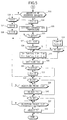
- FIG. 4 shows a first part of a flowchart representing operational steps of a control operation performed in the engine for regulating the concentration of a reductant;
- FIG. 5 shows a second part of the flowchart representing operational steps to follow FIG. 4;
- FIG. 6 is a time chart showing the control operation performed in the engine of the embodiment;
- FIG. 7 is a diagram showing part of the control operation performed in the engine of the embodiment;
- FIG. 8 is a flowchart showing operational steps of an ignition retard control operation which is part of overall control of the engine of the embodiment;
- FIG. 9 is a flowchart showing operational steps of an EGR control operation which is part of the overall control of the engine of the embodiment;
- FIG. 10 is a graph showing a temperature increasing effect obtained when an NOx absorbing material contains ceria (CeO2); and
- FIGS. 11A and 11B are graphs showing an effect obtained when time-split injection was performed with the air-fuel ratio set to make the excess-air factor λ approximately equal to but smaller than 1 (λ≦1) in the aforementioned embodiment.
-
- An engine control device according to a preferred embodiment of the invention is now described with reference to the accompanying drawings.
- Referring to FIG. 1, an
engine body 10 has a plurality ofcylinders 12. Apiston 14 is fitted in eachcylinder 12 and acombustion chamber 16 is formed above the top surface of thepiston 14. In this embodiment, two each intake ports and exhaust ports open into thecombustion chamber 16. These intake ports and exhaust ports are opened and closed by intake valves 17 andexhaust valves 18, respectively. - A
spark plug 20 is provided at the top of thecombustion chamber 16 in eachcylinder 12 in such a way that a spark gap of thespark plug 20 is located inside thecombustion chamber 16. Aninjector 22 is fitted in one side of thecombustion chamber 16 with an extreme end (fuel injecting part) of theinjector 22 located in thecombustion chamber 16 so that fuel can be injected directly from theinjector 22 into thecombustion chamber 16. This engine is therefore a direct injection engine. Theinjector 22 of eachcylinder 12 incorporates a needle valve and a solenoid which are not illustrated. Theinjector 22 injects a specific amount of fuel which is determined by the pulselength of a later-described pulse signal at the time when the pulse signal is entered to the solenoid. - The aforementioned intake ports are connected to an
intake passage 24. Anair cleaner 25,airflow sensor 26, anelectric throttle unit 28 including a throttle sensor and a throttle valve, and asurge tank 30 are provided in this order in theintake passage 24 from its upstream side to downstream side. Theintake passage 24 branches into independent intake passages downstream of thesurge tank 30. - In the example illustrated in FIG. 1, downstream portions of each independent intake passage branches into first and
second channels combustion chamber 16, and an on/offvalve 31 for producing a swirl is provided only in thesecond channel 24b. This on/offvalve 31 is opened and closed by an actuator (not shown). When the on/offvalve 31 closes off thesecond channel 24b, a swirl is produced in thecombustion chamber 16 by intake air introduced through thefirst channel 24a alone. The swirl becomes less intense as the opening of the on/offvalve 31 increases. - On the other hand, the aforementioned exhaust ports are connected to an
exhaust passage 34. A three-waycatalytic material 35 and a lean NOxcatalytic material 36, that is, NOx-absorbingmaterial 36, are provided in this order in theexhaust passage 34 from its upstream side. Each of thesecatalytic materials - The three-way
catalytic material 35 converts NOx, CO and hydrocarbons (HC) contained in exhaust gas when its air-fuel ratio is approximately equal to the stoichiometric air-fuel ratio. Compared to this, the NOx-absorbingmaterial 36 absorbs NOx under lean conditions in which the excess-air factor of the exhaust gas is large and releases the absorbed NOx under rich conditions in which the excess-air factor of the exhaust gas is small. The NOx-absorbingmaterial 36 exhibits greater converting performance when the exhaust gas temperature falls in a particular range which is lower than exhaust gas temperatures suited for the operation of the three-waycatalytic material 35. A preferable example of this kind of NOx-absorbing material is disclosed in Japanese Unexamined Patent Publication No. 10-151353, for example, in which an inner catalyst layer formed of alumina containing noble metal like platinum and alkaline earth metal like barium and an outer catalyst layer formed of zeolite containing platinum and rhodium are deposited on a carrier. Also, it is preferable that the NOx-absorbingmaterial 36 be of a type containing ceria (CeO2). When the NOx-absorbingmaterial 36 contains ceria, it is possible to gradually release oxygen (O2) absorbed under lean conditions by making the exhaust gas richer (λ≦ 1), and maintain the NOx-absorbingmaterial 36 at high temperatures achieved by time-split injection, for instance, by causing the oxygen released from ceria to react particularly with CO. - There is provided an EGR
passage 32 for recirculating part of the exhaust gas between theintake passage 24 and theexhaust passage 34. An inflow end of the EGRpassage 32 is connected to theexhaust passage 34 upstream of the three-waycatalytic material 35, while an outflow end of theEGR passage 32 is connected to theintake passage 24 of an intake manifold downstream of the electric throttle unit 28 (but upstream of the surge tank 30). AnEGR valve 33 is provided at the outflow end of theEGR passage 32. TheEGR valve 33 regulates the amount of exhaust gas recirculated through theEGR passage 32. - This engine is provided with various sensors, such as an
engine speed sensor 37 and anaccelerator depression sensor 38, in addition to the earlier-mentioned throttle sensor andairflow sensor 26. Output signals (sensing signals) from these sensors are entered to an electronic control unit (ECU) 40, which comprises anoperating condition identifier 42, athrottle controller 44, areductant concentration controller 46, anEGR controller 48 and a time-split injection controller 49 (or an ignition retard controller 50). - FIG. 2 is a chart showing operating ranges of the engine defined according to engine speed Ne and engine load Ce. The
operating condition identifier 42 takes in the output signals from the aforementioned sensors and makes a judgment as to which operating range the engine is currently operated in. - In FIG. 2, region "A" represents a low/medium-speed, low-load operating range in which the amount of injected fuel is small. In the region A, the fuel is injected only once in a latter half of each compression stroke to produce stratified charge combustion, wherein the air-fuel ratio within the
entire combustion chamber 16 is high (lean mixture) but a relatively rich mixture mass is locally present in an area immediately around thespark plug 20. - Region "B" in FIG. 2 represents a low-speed range in which the engine speed is less than a specified value and the engine load is higher than in the region A. In this region B, the fuel is injected once in each intake stroke to produce uniform charge combustion of a mixture whose excess-air factor λ is equal to or smaller than 1 (λ≦1).
- Region "C" in FIG. 2 includes a medium/high-speed, high-load operating range and a high-speed, low-load operating range in which the engine speed is equal to or higher than the specified value. Although uniform charge combustion is produced in the region C as in the region B, the fuel is injected more than once in each intake stroke. This form of time-split injection is referred to as time-split injection mode. In the region C, the fuel is injected more than once in each intake stroke so that the fuel is widely spread and well mixed with air to produce uniform charge combustion of a mixture whose excess-air factor λ is equal to 1 (λ=1).
- In a range where the engine speed is high and the engine load is extremely high, it is difficult to inject the fuel in multiple steps within an intake stroke since the total amount of injected fuel is so large. This is why the region B of one-time injection mode extends to the high-speed side in the example shown in FIG. 2.
- The
throttle controller 44 controls the opening of the throttle valve of theelectric throttle unit 28 based on the sensing signal fed back from the throttle sensor to regulate the amount of intake air so that it is suited for combustion in each engine operating range. - The
reductant concentration controller 46 controls the concentration of reductant by adjusting the amount of injected fuel and injection timing. More specifically, thereductant concentration controller 46 performs, in addition to an ordinary control operation to make combustion suited to the operating range identified by theoperating condition identifier 42, a control operation for eliminating NOx and SOx. When performing the latter control operation, thereductant concentration controller 46 determines the amount of fuel to be injected and injection timing such that the amount of CO which serves as a reducing agent would increase, and outputs a command signal to an unillustrated injector driver, causing it to output a pulse signal whose pulselength corresponds to the amount of fuel to be injected to theinjector 22 at the injection timing determined. In the present embodiment, this control operation for regulating the concentration of the reductant is carried out according to a flowchart shown in FIGS. 4 and 5 and specific commands derived from the control operation of thereductant concentration controller 46 are output to theEGR controller 48, the time-split injection controller 49 and/or theignition retard controller 50, as will be described later. - The
EGR controller 48 controls the opening of theEGR valve 33 such that the actual amount of exhaust gas recirculated through theEGR passage 32 coincides with a target value set for each engine operating range. In this embodiment, theEGR controller 48 performs, in addition to an ordinary EGR control operation for normal operating conditions, a control operation for reducing the amount of the recirculated exhaust gas via theEGR valve 33 when it has been judged that a control operation for desulfurization should be carried out in combination with the control operation performed by thereductant concentration controller 46. - When data on the amount of fuel to be injected in an earlier injection cycle and an earlier injection point as well as the amount of fuel to be injected in a later injection cycle and a later injection point obtained when the
reductant concentration controller 46 performs its control operation is entered to the time-split injection controller 49, it causes theinjector 22 to inject the specified amounts of fuel at the specified injection points in successive cycles. - When data on an ignition point derived by correcting a basic ignition point which is obtained when the
reductant concentration controller 46 performs its control operation is entered to theignition retard controller 50, it causes thespark plug 20 to ignite the mixture at the specified ignition point. - The
reductant concentration controller 46, theEGR controller 48, the time-split injection controller 49 and theignition retard controller 50 together constitutes a desulfurization controller which increases the temperature of the NOx-absorbingmaterial 36 and supplies it with the reductant when the amount of sulfur absorbed by the NOx-absorbingmaterial 36 has reached a prescribed quantity. - Now, the reductant concentration control operation performed by the
ECU 40 is described specifically referring to a time chart of FIG. 3 and the flowchart of FIGS. 4 and 5. - Referring to FIG. 4, the
reductant concentration controller 46 initiates its control operation for eachcylinder 12 of the engine with specific timing. Specifically, thereductant concentration controller 46 takes in such data as engine speed Ne, accelerator depression acc and the output of theairflow sensor 26 from theoperating condition identifier 42 in step S1, and sets basic fuel injection quantity TB based on such data in step S2. Thereductant concentration controller 46 sets an air-fuel ratio based on the engine speed Ne, accelerator depression acc and the current operating range (region A, B or C shown in FIG. 2) of the engine and calculates the basic fuel injection quantity TB using the air-fuel ratio, the amount of intake air and the engine speed Ne. - Next, a judgment is made as to whether time-split injection is currently made in step S3. If time-split injection mode is currently selected, the operation flow proceeds to step S4, in which the earlier fuel injection quantity Tm is set as an earlier fuel injection quantity basic value Tm1 and the earlier injection point Im is set as an earlier injection point basic value Im1 in step S4. Then in step S5, the later fuel injection quantity Tt is set as a later fuel injection quantity basic value Tt1 and the later injection point It is set as a later injection point basic value It1, and the operation flow proceeds to step S10. The earlier and later fuel injection quantity basic values Tm1, Tt1 are determined based on the basic fuel injection quantity TB and specified proportions of fuel to be injected in the earlier and later injection cycles.
- On the other hand, if it is judged that the time-split injection mode is not currently selected in step S3, a judgment is made to determine whether the fuel is to be injected in the later injection cycle only in step S6. If the judgment result in step S6 is in the affirmative, the later fuel injection quantity Tt is set to Tt2 (the earlier fuel injection quantity Tm is set to 0) and the later injection point It is set to It2 (the earlier injection point Im is set to 0) in step S7, and the operation flow proceeds to step S10. If it is judged that the engine is in a fuel cutoff condition in step S8, the operation flow of FIG. 4 is terminated because no control operation needs to be carried out. If the judgment result in step S6 is in the negative and the engine is not in the fuel cutoff condition in step S8, the earlier fuel injection quantity Tm is set to Tm3 (the later fuel injection quantity Tt is set to 0) and the earlier injection point Im is set to Im3 (the later injection point It is set to 0) in step S9, and the operation flow proceeds to step S10. Initialization of the
ECU 40 is finished by the foregoing steps. - Subsequently, the amount of absorbed NOx is estimated in step S10. This estimation is made based on the distance traveled under lean mixture conditions and the total amount of fuel (Qa) injected since an NOx release control operation was last executed. The estimated amount of the absorbed NOx is compared with its reference value NO in step S11. If the estimated amount of the absorbed NOx is equal to or greater than NO (the quantity of absorbed NOx≧ NO), an NOx release control execute flag F1 is set in step S12. Then, count value T1 of a timer is incremented by 1 in step S13, and a judgment is made to check whether T1≧T10 in step S15, where T10 represents a time period which elapses just before the NOx in the NOx-absorbing
material 36 begins to be rapidly released as shown in FIG. 3. If T1 ≧T10 in step S15, the earlier fuel injection quantity Tm is set to Tm4, the later fuel injection quantity Tt is set to Tt4, the earlier injection point Im is set to Im4, and the later injection point It is set to It4 in step S17. In this case, the air-fuel ratio is set to a value approximately equal to the stoichiometric air-fuel ratio, i.e., excess-air factor λ is equal to 1. Then, the operation flow proceeds to step S18. - If T1<T10 in step S15 and the engine is of a four-cylinder type, a judgment is made to determine whether the
cylinder 12 into which the fuel is to be injected next is the first orfourth cylinder 12 in step S16. If the judgment result in step S16 is in the negative, that is, the fuel is to be injected into the second orthird cylinder 12 next, the operation flow proceeds to step S17 to make time-split injection, and then to step S18. If the judgment result in step S16 is in the affirmative, that is, the fuel is to be injected into the first orfourth cylinder 12 next, the operation flow proceeds directly to step S18. This means that the first orfourth cylinder 12 is controlled in the same conditions as before (e.g., lean mixture conditions) and the second orthird cylinder 12 is operated in the time-split injection mode at λ≒1 until the time period T10 elapses. During a time period from T10 to T12, all thecylinders 12 are operated in the time-split injection mode at λ≒1. Time-split injection is made during a period from an intake stroke to a succeeding compression stroke. The earlier injection point Im and the later injection point It are set such that the earlier injection cycle occurs in a first half of the intake stroke and the later injection cycle occurs in a second half of the compression stroke, for example. As a consequence, some of thecylinders 12 are operated in the time-split injection mode to supply a large quantity of the reductant immediately before the time period from T10 to T11 during which a large quantity of NOx is produced, so that conversion of the NOx can accelerated. As shown in Fig. 3, T11 represents a time period which elapses just before the EGR control operation is changed from the normal EGR amount to the reduced EGR amount. - In step S18, a judgment is made to check whether T1≧ T12, where T12 is a point in time (from which the air-fuel ratio begins to become high) that occurs after the point in time T11, as shown in FIG. 6. If T1≧T12 in step S18, the NOx release control execute flag F1 is reset in step S19 and the operation flow proceeds to step S20. If T1<T12 in step S18, the operation flow proceeds to step S23.
- If the estimated amount of the absorbed NOx is smaller than NO (absorbed NOx<NO) in step S11, the operation flow proceeds to step S13, in which a judgment is made to check whether the NOx release control execute flag F1 is currently set to 1. If the judgment result in step S13 is in the affirmative, the operation flow proceeds to step S14. If the judgment result in step S13 is in the negative, that is, the NOx release control execute flag F1 is not currently set, the NOx release control execute flag F1 is reset in step S21 and T1 is reset to 0 in step S22. Then, the operation flow proceeds to step S20.
- In step S20, the amount of absorbed SOx is estimated. This estimation is made based on the distance traveled and the total amount of fuel injected since a sulfur release control operation was last executed, as well as on a time period during which the temperature of the NOx-absorbing
material 36 is low. The estimated amount of the absorbed SOx is compared with its reference value SO in step S23 of FIG. 5. If the estimated amount of the absorbed SOx is equal to or greater than SO (the quantity of absorbed SOx≧ SO), a sulfur release control execute flag F2 is set in step S24 and exhaust gas temperature Tc is estimated in step S25. The estimation of the exhaust gas temperature Tc is made based on a time period during which the air-fuel ratio has been high and a time period during which time-split injection has been made, for instance. When the sulfur release control execute flag F2 has been set in step S24, a later-described ignition retard control operation and the EGR control operation are performed with specific timing. - The estimated exhaust gas temperature Tc is compared with its reference value Tc0 in step S26. If Tc≧Tc0, count value T2 of a timer is incremented by 1 in step S27, and a judgment is made to check whether T2≧T10 in step S28. If T2≧T10 in step S28, the earlier fuel injection quantity Tm is set to Tm4+Tcm (additional fuel quantity), the later fuel injection quantity Tt is set to Tt4+Tct (additional fuel quantity), the earlier injection point basic value Im is set to Im4, and the later injection point basic value It is set to It4 in step S29. These settings are made to perform time-split injection at a low air-fuel ratio (λ≦1 for a rich mixture) to increase the amount of CO. As a result of these settings, it becomes possible to previously supply CO in sufficient quantity for reducing the NOx released from the NOx-absorbing
material 36. - Subsequently, time T20 is set in step S30 and a judgment is made to check whether T2≧T20 in step S31. If T2≧T20 in step S31, the sulfur release control execute flag F2 is reset to 0 in step S32 and the operation flow proceeds to step S33.
- On the other hand, if T2<T10 in step S28, additional fuel quantity Tcm is set to 0 and additional fuel quantity Tct is set to 0 in step S34. Then, a judgment is made to determine whether the
cylinder 12 into which the fuel is to be injected next is the first orfourth cylinder 12 in step S35. If the judgment result in step S35 is in the negative, the operation flow proceeds to step S29 to perform time-split injection at an excess-air factor of λ≦1 to increase the amount of CO as described above. If the judgment result in step S35 is in the affirmative, that is, the fuel is to be injected into the first orfourth cylinder 12 next, the operation flow proceeds to step S30. As a result, the second andthird cylinders 12 are operated in the time-split injection mode at a low air-fuel ratio and the CO concentration in the exhaust gas from thesecylinders 12 becomes high. Consequently, the CO discharged from the second andthird cylinders 12 reacts with oxygen discharged from the first andfourth cylinders 12, and the resultant heat of reaction promotes temperature increase. - If the estimated amount of the absorbed SOx is smaller than its reference value SO (the quantity of absorbed SOx<SO) in step S23, the operation flow proceeds to step S36, in which a judgment is made to check whether the sulfur release control execute flag F2 is currently set to 1. If the judgment result in step S36 is in the affirmative, the operation flow proceeds to step S25. If the judgment result in step S36 is in the negative, T2 is reset to 0 in step S37, the sulfur release control execute flag F2 is reset to 0 in step S38, and the operation flow proceeds to step S33.
- In step S33, a judgment is made to check whether the earlier fuel injection quantity Tm is equal to 0. If the judgment result in step S33 is in the negative (Tm≠0), a further judgment is made in step S39 to check whether the earlier injection point Im has been reached. When the earlier injection point Im has been reached, the fuel is injected as much as the earlier fuel injection quantity Tm in step S40, and the operation flow proceeds to step S41. On the other hand, if Tm=0 in step S33, the operation flow proceeds to step S41.
- In step S41, a judgment is made to check whether the later fuel injection quantity Tt is equal to 0. If the judgment result in step S41 is in the negative (Tt≠0), a further judgment is made to check whether the later injection point It has been reached in step S42. When the later injection point It has been reached, a control command is issued in step S43 to inject the fuel as much as the later fuel injection quantity Tt. According to the foregoing steps, time-split injection is made when neither of the earlier and later fuel injection quantities Tm, Tt is zero, and in this case, the amount of the constituent reducing agent (CO) in the reductant is increased and the NOx in the NOx-absorbing
material 36 is reduced. - The aforementioned time-split injection control operation is applicable to a case in which the engine load Ce is low as shown by region "D" in FIG. 7. In high engine load region "E" shown in FIG. 7, it is preferable to mainly perform the ignition retard control operation. More specifically, since the temperature is increased in the region E, it is preferable to increase the amount of ignition retardation in the region E than in the region D, prohibit the time-split injection control operation in the region E, and increase EGR control amount in the region D than in the region E. By mainly performing the ignition retard control operation in high-load conditions, it is possible to promote temperature increase while preventing the occurrence of knocking in a region in which it is difficult to recirculate the exhaust gas. Also by performing the time-split injection control operation and EGR control operation in low-load conditions, it is possible to make time-split injection which can easily produce a stratified mixture, and to perform the EGR control operation under conditions in which exhaust gas recirculation can be easily made.
- Engine speed fluctuation increases if the ignition retard control operation is mainly performed in the low/medium-speed, low-load operating range. Therefore, it is preferable to give priority to the time-split injection control operation and EGR control operation in low-load conditions, rather than to the ignition retard control operation, in the low/medium-speed, low-load operating range
- Referring to FIG. 8, the
ignition retard controller 50 initiates its control operation at specific crank angles. Specifically, theignition retard controller 50 takes in such data as the engine load Ce and the engine speed Ne in step S100 and sets a basic ignition point B based on these data in step S101. Then, a judgment is made to check whether the sulfur release control execute flag F2 for the aforementioned time-split injection is currently set in step S102. If the judgment result in step S102 is in the affirmative, a first ignition point correction value c1 is set in step S103, where the first ignition point correction value c1 (which specifies the amount of ignition retardation) is made smaller in the region D of FIG. 7, larger in the region E. Then in step S104, a judgment is made to check whether T2≧T10. If the judgment result in step S104 is in the negative, a second ignition point correction value c2 (which specifies the amount of ignition retardation) is set to 0 in step S105. This setting is made to give priority to fuel economy in an initial stage in which the amount of sulfur released is small. Subsequently, ignition point T is calculated by the equation - If the judgment result in step S102 is in the negative, that is, the sulfur release control execute flag F2 is not set, the operation flow proceeds to step S106. Also, if T2 ≧T10 in step S104, a further judgment is made to check whether T2<T11 in step S107. If the judgment result in step S107 is in the negative, the operation flow proceeds to step S105. If T2<T11 (i.e., T11>T2≧T10) in step S107, the second ignition point correction value c2 is set to m(>0) in step S108 and the operation flow proceeds to step S106. This setting is made to increase the temperature of the NOx-absorbing
material 36 and to increase the amount of CO, disregarding the fuel economy. Here, a judgment is made in step S109 to check whether the ignition point T calculated in step S106 has been reached. When the ignition point T has been reached, the mixture is ignited in step S110. According to the foregoing steps, it is possible to remarkably increase the concentration of the constituent reducing agent (CO) and the temperature of the NOx-absorbingmaterial 36 when the amount of released NOx reaches its maximum point. - Referring to FIG. 9, the
EGR controller 48 initiates its control operation at specific crank angles. Specifically, theEGR controller 48 takes in such data as the engine load Ce and the engine speed Ne in step S120 and sets a basic EGR quantity EGRB, such as EGR valve opening determined based on EGR ratio, in step S121. Then, a judgment is made in step S122 to check whether the sulfur release control execute flag F2 for the aforementioned control operation performed by thereductant concentration controller 46 is currently set. If the judgment result in step S122 is in the affirmative, a further judgment is made to check whether T2≧T11 in step S123. If T2≧T11 in step S123, an EGR correction value EGRC for reducing the amount of the recirculated exhaust gas is set in step S124. Here, even if the same EGR correction value EGRC, or the same EGR valve opening, is applied to the regions D and E of FIG. 7, a greater amount of exhaust gas is recirculated in the low-load region D. It is however preferable that the EGR correction value EGRC be made larger in the region D than in the region E. In succeeding step S126, true EGR quantity EGRT is calculated by the equation - If it is judged that
F2 1 in step S122 or T2<T11 in step S123, the EGR correction value EGRC is set to 0 in step S125 and the operation flow proceeds to step S126. Subsequently, theEGR valve 33 is operated with the true EGR quantity EGRT thus obtained in step S127. According to the aforementioned engine control device of the embodiment, when thereductant concentration controller 46 constituting the desulfurization controller decreases a quantity related to the EGR ratio, the exhaust gas temperature increases, causing an increase in the temperature of the NOx-absorbingmaterial 36. As a consequence, sulfur within the NOx-absorbingmaterial 36 is freed and released. Since the quantity related to the EGR ratio is decreased by theEGR valve 33 which is already provided in the engine having the capability of performing the EGR control operation, it is not necessary to additionally provide a space-consuming desulfurization control device. It is therefore appreciated that the invention makes it possible to achieve space savings without causing cost increase. - When the ignition retard control operation and time-split injection are performed before decreasing the quantity related to the EGR ratio as in the engine control device of this embodiment, it is possible to increase the amount of the constituent reducing agent (CO) and improve the efficiency of eliminating the sulfur within the NOx-absorbing
material 36 compared to a case in which only the EGR control operation is performed. Furthermore, if the ignition retard control operation or time-split injection is first performed and the amount of the recirculated exhaust gas is reduced after the amount of NOx released from the NOx-absorbingmaterial 36 has reached its maximum point, the amount of raw NOx (which is contained in the exhaust gas prior to catalytic conversion) is decreased by exhaust gas recirculation until the amount of the released NOx reaches its maximum point. Since the amount of the reductant consumed for reducing the raw NOx is decreased, the effect of reducing the released NOx is enhanced and the maximum amount of the released NOx can be lowered. When the amount of the released NOx is decreased in this manner, it becomes possible to achieve a temperature increase by reducing the amount of the recirculated exhaust gas (or cutting off the recirculated exhaust gas). It is to be noted that either the ignition retard control operation or time-split injection may be performed alone, instead of performing both. - FIG. 10 is a graph showing a temperature increasing effect obtained when the NOx-absorbing
material 36 contains ceria (CeO2), in which the horizontal axis represents elapsed time and the vertical axis represents the temperature at an outlet of the NOx-absorbingmaterial 36. - When the exhaust gas becomes rich and the amount of oxygen decreases in a region surrounded a broken line of FIG. 10, the exhaust gas temperature would quickly decrease if the NOx-absorbing
material 36 does not contain ceria, because neither HC nor CO can be reacted in this condition. If the NOx-absorbingmaterial 36 contains ceria, however, oxygen is supplied from the ceria for a while, so that oxidation of HC and CO continues. This serves to maintain high temperatures. - FIGS. 11A and 11B are graphs showing an effect obtained when time-split injection was performed to make the excess-air factor λ approximately equal to 1 (λ≒1) in the aforementioned embodiment. More specifically, FIGS. 11A and 11B show data on the CO concentration and exhaust gas temperature obtained when the later injection timing was varied with the earlier injection timing kept at a fixed point (e.g., -300° CA relative to the compression top dead center). In these graphs, the horizontal axis represents the crank angle relative to the compression top dead center, or after the top dead center (ATDC). Only the leftmost small squares in these graphs represent test results obtained when one-time injection was performed, while the remaining small squares represent test results obtained when time-split injection was performed. The ratio of the amount of fuel injected in the earlier injection cycle to the amount of fuel injected in the later injection cycle in testing was 1:1.
- As can be seen from FIGS. 11A and 11B, when time-split injection is performed at λ≦1, the exhaust gas becomes rich in CO and the exhaust gas temperature increases. Both the amount of CO and the exhaust gas temperature significantly increase especially in a range of 90° to 50° before the compression top dead center, and this serves to improve the efficiency of eliminating the sulfur from the NOx-absorbing
material 36. - It is to be pointed out that the invention is not limited to the foregoing embodiment but is applicable to the following embodiments as well.
- While the engine control device of the foregoing embodiment has the capability to perform the EGR control operation, the invention is also applicable to an engine in which the EGR control operation is not performed. As an example, the invention may be applied to a construction including an NOx-absorbing material which is provided in an exhaust passage, absorbs NOx in an oxygen-rich atmosphere, and releases NOx and absorbs sulfur content when the oxygen concentration drops, a discriminator for judging whether the amount of sulfur absorbed by the NOx-absorbing material is equal to or smaller than a specific reference value, and a reductant concentration controller which performs an ignition retard control operation or at least two-step time-split injection during a period from an intake stroke to a succeeding compression stroke, or both, based on the result of judgment made by the discriminator, wherein the reductant concentration controller gives high priority to the ignition retard control operation. According to this construction, it is possible to increase the temperature of the NOx-absorbing material without performing the EGR control operation and the occurrence of knocking can be prevented.
- Although the fuel is injected twice, firstly in the intake stroke and secondly in the compression stroke, in the earlier-mentioned embodiment, it may be injected three or more times in successive steps. In this variation, the first two injection cycles may occur during the intake stroke.
- Although the invention is applied to the direct injection engine in the foregoing embodiment, the invention is not limited thereto but is widely applicable to engines having adjacent operating ranges in which different target amounts of recirculated exhaust gas are set. In a port injection engine in which the fuel is injected into an intake port upstream of an intake valve, for example, it is desirable to decrease the amount of the recirculated exhaust gas or retard the ignition timing when the amount of absorbed sulfur increases in an operating range in which a high target amount of recirculated exhaust gas is set (e.g., in an operating range in which stratified charge combustion is made by injecting the fuel in a latter part of each intake stroke and producing a swirl).
- As described above, an inventive engine control device is adapted for controlling an engine provided with a fuel injection valve for supplying the engine with fuel, an EGR regulator for recirculating part of exhaust gas to an intake air line, an ignition timing controller for controlling ignition timing, an NOx-absorbing material arranged in an exhaust passage for discharging the exhaust gas from a combustion chamber for absorbing NOx in an oxygen-rich atmosphere, and releasing NOx and absorbing sulfur content when the oxygen concentration drops. The engine control device comprises: a discriminator for judging whether the amount of sulfur absorbed by the NOx-absorbing material has reached a prescribed quantity; and a desulfurization controller which controls at least one of the ignition timing controller and the EGR regulator to increase the temperature of the NOx-absorbing material and thereby desulfurizes the NOx-absorbing material based on the result of judgment made by the discriminator. The desulfurization controller causes the EGR regulator to decrease EGR ratio when the amount of sulfur absorbed by the Nox-absorbing material is judged to have reached or exceeded a prescribed quantity.
- In this construction, when the desulfurization controller decreases a quantity related to the EGR ratio, the exhaust gas temperature increases, causing an increase in the temperature of the NOx-absorbing material. As a consequence, sulfur within the NOx-absorbing material is freed and released. Since the quantity related to the EGR ratio is decreased by the EGR regulator which is already provided in the engine having the capability of performing EGR control operation, it is not necessary to additionally provide a space-consuming desulfurization control device. This makes it possible to achieve space savings without causing cost increase.
- The prescribed quantity of absorbed sulfur is a quantity from which the NOx-absorbing ability of the NOx-absorbing material becomes lower than a specified level as a result of adsorption of sulfur.
- The aforementioned desulfurization controller may include a reductant concentration controller which performs a control operation for increasing the concentration of a reductant contained in the exhaust gas.
- According to this construction, the concentration of the reductant (e.g., carbon monoxide) can be increased by means of the reductant concentration controller while increasing the temperature of the NOx-absorbing material. It is therefore possible to promote desulfurization of the NOx-absorbing material.
- The control device may be constructed such that the reductant concentration controller begins the control operation for increasing the concentration of the reductant and decreases a quantity related to the EGR ratio after the amount of NOx released from the NOx-absorbing material has reached its maximum point when the discriminator has judged that the amount of sulfur absorbed by the NOx-absorbing material has reached the prescribed quantity.
- In this construction, the amount of raw NOx (which is contained in the exhaust gas prior to catalytic conversion) is decreased by exhaust gas recirculation while the amount of the released NOx is large. Since the amount of the reductant consumed for reducing the raw NOx is decreased, the effect of reducing the released NOx is enhanced and the maximum amount of the released NOx can be lowered. (When the amount of NOx decreases, it becomes possible to achieve a temperature increase by cutting off the recirculated exhaust gas.)
- The reductant concentration controller may be so constructed as to perform at least an air-fuel ratio control operation for increasing the amount of injected fuel relative to the amount of intake air to decrease the air-fuel ratio so that excess-air factor λ becomes equal to or smaller than 1, or an ignition retard control operation.
- This construction makes it possible to easily increase the concentration of a reductant by the air-fuel ratio control operation or by the ignition retard control operation.
- In the case that the engine is provided with an injector for injecting the fuel directly into the combustion chamber, and the reductant concentration controller causes the injector to make at least two-step time-split injection during a period from an intake stroke to a succeeding compression stroke when performing the air-fuel ratio control operation, it is preferable to set the air-fuel ratio such that the excess-air factor λ becomes approximately equal to 1. This construction makes it possible to increase the temperature of the NOx-absorbing material without causing a significant deterioration in fuel economy.
- The reductant concentration controller may be so constructed as to increase the amount of ignition retardation before the amount of NOx released from the NOx-absorbing material reaches its maximum point when performing the ignition retard control operation. This construction makes it possible to remarkably increase the concentration of CO which serves as a constituent reducing agent and promote temperature increase of the NOx-absorbing material when the amount of released NOx reaches its maximum point.
- The reductant concentration controller may be so constructed as to increase the air-fuel ratio in at least one cylinder and decrease the air-fuel ratio in any other cylinder so that the excess-air factor λ in the latter cylinder becomes approximately equal to or smaller than 1 before performing the air-fuel ratio control operation. This construction makes it possible to supply the constituent reducing agent for increasing the amount of released NOx in advance.
- The reductant concentration controller may be so constructed as to produce at least two-step time-split injection during a period from an intake stroke to a succeeding compression stroke into the cylinder whose excess-air factor λ is made equal to or smaller than 1. In this construction, the concentration of the constituent reducing agent (CO) becomes high since time-split injection is performed in the cylinder whose air-fuel ratio is low. The reducing agent (CO) rapidly reacts with oxygen (O2) discharged from the cylinder whose air-fuel ratio is high, so that it is possible to increase the temperature of the NOx-absorbing material and improve the efficiency of eliminating sulfur from the NOx-absorbing material.
- The reductant concentration controller may be so constructed as to produce at least two-step time-split injection during a period from an intake stroke to a succeeding compression stroke before performing the air-fuel ratio control operation. This construction makes it possible to remarkably increase the concentration of the constituent reducing agent and the temperature of the NOx-absorbing material when the amount of released NOx reaches its maximum point. Moreover, the temperature of the NOx-absorbing material can be increased in advance.
- The amount of ignition retardation is made larger in high-load conditions than in low-load conditions. This construction makes it possible to promote desulfurization of the NOx-absorbing material while preventing the occurrence of knocking by ignition retardation in a high-load range in which engine knocking is likely to occur and deterioration in combustibility tends to be caused by exhaust gas recirculation or time-split injection.
- The amount of controlling the EGR ratio is made larger in low-load conditions than in high-load conditions.
- Further, the control device may be so constructed as to perform a desulfurization control operation by executing the ignition retard control operation while prohibiting time-split injection in high-load conditions and perform the desulfurization control operation by making time-split injection in low-load conditions. In this construction, the amount of CO can be increased by performing time-split injection in a low-load range in which a stratified mixture can be easily produced.
- Moreover, an inventive engine control device is adapted for controlling an engine provide with a fuel injection valve for injecting fuel directly into a combustion chamber of the engine, an ignition timing controller for controlling ignition timing, an NOx-absorbing material arranged in an exhaust passage for discharging exhaust gas from the combustion chamber for absorbing NOx in an oxygen-rich atmosphere, and releasing NOx and absorbing sulfur content when the oxygen concentration drops, and includes a discriminator for judging whether the amount of sulfur absorbed by the NOx-absorbing material has reached a prescribed quantity, and a desulfurization controller which causes the ignition timing controller to perform an ignition retard control operation or the fuel injection valve to inject the fuel at least twice during a period from an intake stroke to a succeeding compression stroke based on the result of judgment made by the discriminator in order to desulfurize the NOx-absorbing material by increasing its temperature. The desulfurization controller performs a desulfurization control operation by executing the ignition retard control operation while prohibiting time-split injection in high-load conditions and performs the desulfurization control operation by making time-split injection in low-load conditions when the discriminator has judged that the amount of sulfur absorbed by the NOx-absorbing material has reached or exceeded the prescribed quantity.
- According to this construction, it is possible to increase the amount of CO and the exhaust gas temperature by performing the ignition retard control operation or time-split injection. This serves to promote desulfurization of the NOx-absorbing material. This construction is particularly effective for preventing knocking in high-load ranges since ignition retardation and time-split injection can be selectively performed depending on operating conditions.
Claims (15)
- An engine control device for controlling an engine provided with a fuel injection valve for supplying the engine with fuel, an EGR regulator for recirculating part of exhaust gas to an intake air line, an ignition timing controller for controlling ignition timing, an NOx-absorbing material arranged in an exhaust passage for discharging the exhaust gas from a combustion chamber for absorbing NOx in an oxygen-rich atmosphere, and releasing NOx and absorbing sulfur content when the oxygen concentration drops, the engine control device comprising:a discriminator for judging whether the amount of sulfur absorbed by the NOx-absorbing material has reached a prescribed quantity; anda desulfurization controller which controls at least one of the ignition timing controller and the EGR regulator to increase the temperature of the NOx-absorbing material and thereby desulfurizes the NOx-absorbing material based on the result of judgment made by the discriminator.
- The control device according to claim 1, wherein the desulfurization controller causes the EGR regulator to decrease EGR ratio when the amount of sulfur absorbed by the Nox-absorbing material is judged to have reached or exceeded a prescribed quantity.
- The control device according to claim 2, wherein the prescribed quantity of absorbed sulfur is a quantity from which the NOx-absorbing ability of the NOx-absorbing material becomes lower than a specified level as a result of adsorption of sulfur.
- The control device according to any one of claims 1 to 3, wherein the desulfurization controller includes a reductant concentration controller which performs a control operation for increasing the concentration of a reductant contained in the exhaust gas.
- The control device according to claim 4, wherein the reductant concentration controller begins the control operation for increasing the concentration of the reductant and decreases a quantity related to the EGR ratio after the amount of NOx released from the NOx-absorbing material has reached its maximum point when the discriminator has judged that the amount of sulfur absorbed by the NOx-absorbing material has reached the prescribed quantity.
- The control device according to claim 5, wherein the reductant concentration controller performs at least an air-fuel ratio control operation for increasing the amount of injected fuel relative to the amount of intake air to decrease the air-fuel ratio so that excess-air factor λ becomes equal to or smaller than 1, or an ignition retard control operation.
- The control device according to claim 6, wherein the engine is provided with an injector for injecting the fuel directly into the combustion chamber, and the reductant concentration controller causes the injector to make at least two-step time-split injection during a period from an intake stroke to a succeeding compression stroke when performing the air-fuel ratio control operation.
- The control device according to claim 6, wherein the reductant concentration controller increases the amount of ignition retardation before the amount of NOx released from the NOx-absorbing material reaches its maximum point when performing the ignition retard control operation.
- The control device according to claim 6, wherein the reductant concentration controller increases the air-fuel ratio in at least one cylinder and decreases the air-fuel ratio in any other cylinder so that the excess-air factor λ in the latter cylinder becomes approximately equal to or smaller than 1 before performing the air-fuel ratio control operation.
- The control device according to claim 9, wherein the reductant concentration controller produces at least two-step time-split injection during a period from an intake stroke to a succeeding compression stroke into the cylinder whose excess-air factor λ is made equal to or smaller than 1.
- The control device according to claim 6, wherein the reductant concentration controller produces at least two-step time-split injection during a period from an intake stroke to a succeeding compression stroke before performing the air-fuel ratio control operation.
- The control device according to claim 6, wherein the amount of ignition retardation is made larger in high-load conditions than in low-load conditions.
- The control device according to claim 12, wherein the amount of controlling the EGR ratio is made larger in low-load conditions than in high-load conditions.
- The control device according to claim 7, wherein the control device performs a desulfurization control operation by executing the ignition retard control operation while prohibiting time-split injection in high-load conditions and performs the desulfurization control operation by making time-split injection in low-load conditions.
- The control device according to claim 1, wherein the engine is provided with an injector for injecting the fuel directly into the combustion chamber, and the desulfurization controller performs desulfurization control operation by executing an ignition retard control operation while prohibiting a time-split injection in high-load conditions, and executing a time-split injection in low-load conditions when the discriminator has judged that the amount of sulfur absorbed by the NOx-absorbing material has reached or exceeded the prescribed quantity.
Applications Claiming Priority (2)
| Application Number | Priority Date | Filing Date | Title |
|---|---|---|---|
| JP02921999A JP3632483B2 (en) | 1999-02-05 | 1999-02-05 | Engine control device |
| JP2921999 | 1999-02-05 |
Publications (3)
| Publication Number | Publication Date |
|---|---|
| EP1026381A2 true EP1026381A2 (en) | 2000-08-09 |
| EP1026381A3 EP1026381A3 (en) | 2002-04-03 |
| EP1026381B1 EP1026381B1 (en) | 2005-04-27 |
Family
ID=12270104
Family Applications (1)
| Application Number | Title | Priority Date | Filing Date |
|---|---|---|---|
| EP00102062A Expired - Lifetime EP1026381B1 (en) | 1999-02-05 | 2000-02-02 | Engine control device |
Country Status (4)
| Country | Link |
|---|---|
| US (1) | US6269634B1 (en) |
| EP (1) | EP1026381B1 (en) |
| JP (1) | JP3632483B2 (en) |
| DE (1) | DE60019656T2 (en) |
Cited By (1)
| Publication number | Priority date | Publication date | Assignee | Title |
|---|---|---|---|---|
| CN111441870A (en) * | 2019-01-16 | 2020-07-24 | 大众汽车有限公司 | Method for exhaust gas aftertreatment of an internal combustion engine and exhaust gas aftertreatment system |
Families Citing this family (36)
| Publication number | Priority date | Publication date | Assignee | Title |
|---|---|---|---|---|
| US6718756B1 (en) * | 1999-01-21 | 2004-04-13 | Mitsubishi Jidosha Kogyo Kabushiki Kaisha | Exhaust gas purifier for use in internal combustion engine |
| DE19952526A1 (en) * | 1999-10-30 | 2001-05-10 | Bosch Gmbh Robert | Method for operating an internal combustion engine |
| US6481199B1 (en) * | 2000-03-17 | 2002-11-19 | Ford Global Technologies, Inc. | Control for improved vehicle performance |
| US6487849B1 (en) * | 2000-03-17 | 2002-12-03 | Ford Global Technologies, Inc. | Method and apparatus for controlling lean-burn engine based upon predicted performance impact and trap efficiency |
| US6539704B1 (en) * | 2000-03-17 | 2003-04-01 | Ford Global Technologies, Inc. | Method for improved vehicle performance |
| US6490855B1 (en) * | 2000-04-06 | 2002-12-10 | Ford Global Technologies, Inc. | Fueling control during emission control device purging |
| US6659071B2 (en) | 2000-05-08 | 2003-12-09 | Cummins Inc. | Internal combustion engine operable in PCCI mode with early control injection and method of operation |
| DE10043687A1 (en) * | 2000-09-04 | 2002-03-14 | Bosch Gmbh Robert | Coordination of various exhaust gas temperature requirements and appropriate heating or cooling measures |
| DE10054005A1 (en) * | 2000-11-01 | 2002-05-08 | Daimler Chrysler Ag | The system to clean exhaust gas emissions from an IC motor has a nitrogen oxide accumulator, and desulfurizing operating in full and partial modes according to registered temperatures |
| DE10114054A1 (en) * | 2001-03-15 | 2002-09-26 | Volkswagen Ag | Raising externally ignited direct injection combustion engine exhaust gas temperature involves setting injection angle control end for last injection between 80, 10 degrees before TDC |
| JP4393726B2 (en) * | 2001-04-09 | 2010-01-06 | 本田技研工業株式会社 | Exhaust gas recirculation control device for internal combustion engine |
| US6698191B2 (en) * | 2001-08-09 | 2004-03-02 | Ford Global Technologies, Llc | High efficiency conversion of nitrogen oxides in an exhaust aftertreatment device at low temperature |
| JP2003065095A (en) * | 2001-08-27 | 2003-03-05 | Yanmar Co Ltd | Operation control method for internal combustion engine |
| JP3645841B2 (en) * | 2001-08-28 | 2005-05-11 | 本田技研工業株式会社 | Exhaust gas purification device for internal combustion engine |
| US6553757B1 (en) * | 2001-11-19 | 2003-04-29 | Ford Global Technologies, Llc | NOx purge air/fuel ratio selection |
| EP1475521B1 (en) * | 2002-02-12 | 2019-03-27 | Isuzu Motors Limited | Exhaust gas decontamination system and method of exhaust gas decontamination |
| JP3991789B2 (en) | 2002-07-04 | 2007-10-17 | トヨタ自動車株式会社 | An internal combustion engine that compresses and ignites the mixture. |
| JP4385593B2 (en) * | 2002-12-10 | 2009-12-16 | トヨタ自動車株式会社 | Exhaust gas purification device for internal combustion engine |
| JP2005048752A (en) * | 2003-07-31 | 2005-02-24 | Nissan Motor Co Ltd | Engine control device |
| JP3925485B2 (en) * | 2003-11-06 | 2007-06-06 | トヨタ自動車株式会社 | NOx emission estimation method for internal combustion engine |
| US7047730B2 (en) * | 2004-07-08 | 2006-05-23 | International Engine Intellectual Property Company, Llc | De-sulfurization of a NOx adsorber catalyst in a diesel engine exhaust system |
| US20060266018A1 (en) * | 2005-05-31 | 2006-11-30 | Caterpillar Inc. | Exhaust control system implementing sulfur detection |
| CN1325419C (en) * | 2005-12-19 | 2007-07-11 | 北京朗新明环保科技有限公司 | Dehydration method and apparatus of flue gas desulfurization gypsum slurry |
| EP2010762B1 (en) * | 2006-04-13 | 2016-09-28 | Mack Trucks, Inc. | Engine with emissions control arrangement and method of controlling engine emissions |
| US7950226B2 (en) * | 2007-05-14 | 2011-05-31 | Eaton Corporation | LNT-SCR system optimized for thermal gradient |
| JP4966100B2 (en) * | 2007-05-31 | 2012-07-04 | 日立建機株式会社 | Construction machinery |
| DE102008013163A1 (en) * | 2008-03-07 | 2009-09-10 | Alois Dotzer | Diesel engine operated internal combustion engine |
| JP5263107B2 (en) * | 2009-09-29 | 2013-08-14 | トヨタ自動車株式会社 | Operation control device |
| WO2013061425A1 (en) * | 2011-10-26 | 2013-05-02 | トヨタ自動車 株式会社 | Fuel injection control device for internal combustion engine |
| WO2013061426A1 (en) * | 2011-10-26 | 2013-05-02 | トヨタ自動車 株式会社 | Fuel injection control device for internal combustion engine |
| JP5737262B2 (en) * | 2012-10-16 | 2015-06-17 | トヨタ自動車株式会社 | Control device for internal combustion engine |
| US9284909B2 (en) | 2013-08-23 | 2016-03-15 | Ford Global Technologies, Llc | Method and system for knock control |
| KR102177356B1 (en) * | 2014-09-30 | 2020-11-11 | 두산인프라코어 주식회사 | Engine control apparatus and engine control method by urea quality |
| JP2017025718A (en) * | 2015-07-16 | 2017-02-02 | いすゞ自動車株式会社 | Exhaust emission control system |
| KR101887763B1 (en) * | 2016-10-17 | 2018-09-07 | 현대자동차주식회사 | Appratus controlling intake air for engine of vehicle |
| CN111140319B (en) * | 2019-12-31 | 2021-03-16 | 潍柴动力股份有限公司 | A desulfurization control method, device, storage medium and electronic equipment |
Citations (3)
| Publication number | Priority date | Publication date | Assignee | Title |
|---|---|---|---|---|
| JPH0666129A (en) | 1992-08-13 | 1994-03-08 | Toyota Motor Corp | Exhaust gas purification device for internal combustion engine |
| JPH06229322A (en) | 1993-02-05 | 1994-08-16 | Nissan Motor Co Ltd | Exhaust gas recirculating device of internal combustion engine |
| JPH11107740A (en) | 1997-08-06 | 1999-04-20 | Mazda Motor Corp | Engine exhaust purification device |
Family Cites Families (12)
| Publication number | Priority date | Publication date | Assignee | Title |
|---|---|---|---|---|
| JP2671606B2 (en) * | 1990-12-27 | 1997-10-29 | トヨタ自動車株式会社 | Fuel injection controller for direct injection type internal combustion engine |
| DE19510642C2 (en) * | 1994-12-02 | 1997-04-10 | Volkswagen Ag | Method for reducing pollutants in the exhaust gas of an internal combustion engine having multiple cylinders |
| JP3542404B2 (en) * | 1995-04-26 | 2004-07-14 | 本田技研工業株式会社 | Air-fuel ratio control device for internal combustion engine |
| EP1410837B1 (en) * | 1995-09-11 | 2006-03-29 | Toyota Jidosha Kabushiki Kaisha | A method for purifying exhaust gas of an internal combustion engine |
| JP3956437B2 (en) | 1996-09-26 | 2007-08-08 | マツダ株式会社 | Exhaust gas purification catalyst |
| DE19640161A1 (en) * | 1996-09-28 | 1998-04-02 | Volkswagen Ag | NOx emission control process |
| JP3052856B2 (en) * | 1996-10-24 | 2000-06-19 | 三菱自動車工業株式会社 | Exhaust heating device |
| JP3237607B2 (en) * | 1997-05-26 | 2001-12-10 | トヨタ自動車株式会社 | Catalyst poisoning regeneration equipment for internal combustion engines |
| DE59807160D1 (en) * | 1997-07-19 | 2003-03-20 | Volkswagen Ag | Method and device for monitoring the de-sulfation in NOx storage catalysts |
| JP3264226B2 (en) * | 1997-08-25 | 2002-03-11 | トヨタ自動車株式会社 | Exhaust gas purification device for internal combustion engine |
| US5974788A (en) * | 1997-08-29 | 1999-11-02 | Ford Global Technologies, Inc. | Method and apparatus for desulfating a nox trap |
| US5910096A (en) * | 1997-12-22 | 1999-06-08 | Ford Global Technologies, Inc. | Temperature control system for emission device coupled to direct injection engines |
-
1999
- 1999-02-05 JP JP02921999A patent/JP3632483B2/en not_active Expired - Fee Related
-
2000
- 2000-02-02 DE DE60019656T patent/DE60019656T2/en not_active Expired - Fee Related
- 2000-02-02 EP EP00102062A patent/EP1026381B1/en not_active Expired - Lifetime
- 2000-02-03 US US09/497,431 patent/US6269634B1/en not_active Expired - Fee Related
Patent Citations (3)
| Publication number | Priority date | Publication date | Assignee | Title |
|---|---|---|---|---|
| JPH0666129A (en) | 1992-08-13 | 1994-03-08 | Toyota Motor Corp | Exhaust gas purification device for internal combustion engine |
| JPH06229322A (en) | 1993-02-05 | 1994-08-16 | Nissan Motor Co Ltd | Exhaust gas recirculating device of internal combustion engine |
| JPH11107740A (en) | 1997-08-06 | 1999-04-20 | Mazda Motor Corp | Engine exhaust purification device |
Cited By (1)
| Publication number | Priority date | Publication date | Assignee | Title |
|---|---|---|---|---|
| CN111441870A (en) * | 2019-01-16 | 2020-07-24 | 大众汽车有限公司 | Method for exhaust gas aftertreatment of an internal combustion engine and exhaust gas aftertreatment system |
Also Published As
| Publication number | Publication date |
|---|---|
| DE60019656T2 (en) | 2006-02-02 |
| EP1026381A3 (en) | 2002-04-03 |
| EP1026381B1 (en) | 2005-04-27 |
| DE60019656D1 (en) | 2005-06-02 |
| JP2000227023A (en) | 2000-08-15 |
| JP3632483B2 (en) | 2005-03-23 |
| US6269634B1 (en) | 2001-08-07 |
Similar Documents
| Publication | Publication Date | Title |
|---|---|---|
| EP1026381B1 (en) | Engine control device | |
| US7111452B2 (en) | Control device of hydrogen engine | |
| EP0974747B1 (en) | A control system for an internal combustion engine | |
| EP1028243B1 (en) | Control apparatus for direct injection engine | |
| US7089908B2 (en) | Control device and control method for direct injection engine | |
| US6560960B2 (en) | Fuel control apparatus for an engine | |
| US6116208A (en) | Control system for a direct injection-spark ignition engine | |
| US6325041B1 (en) | Control apparatus for spark ignition type direct injection engine | |
| US6588205B1 (en) | Exhaust gas purifying apparatus | |
| US6725650B2 (en) | Exhaust gas purifying system for engine | |
| EP0978643A2 (en) | Control device for direct injection engine | |
| JP2000027711A (en) | Internal combustion engine | |
| EP1128051A2 (en) | Exhaust-gas cleaning devices for an engine and a method of setting its fuel injection timing | |
| US20110203260A1 (en) | Exhaust purification system of internal combustion engine | |
| US6634167B1 (en) | Exhaust temperature raising apparatus and method for internal combustion engine | |
| JPH11218048A (en) | Engine control device | |
| US8539754B2 (en) | Method for an emission-optimized transfer from a mode of an internal combustion engine to another mode | |
| US8201396B2 (en) | Exhaust gas cleaning apparatus for internal combustion engine | |
| US20140331652A1 (en) | Exhaust gas purification device of internal combustion engine | |
| JP3840911B2 (en) | Engine control device | |
| JP3873537B2 (en) | Exhaust gas purification device for internal combustion engine | |
| JPH11218049A (en) | Engine control device | |
| JP2000205020A (en) | Engine fuel injection control device | |
| JP2004068720A (en) | Control unit for direct injection engine | |
| JP2000230446A (en) | Control device for spark ignition type direct injection engine |
Legal Events
| Date | Code | Title | Description |
|---|---|---|---|
| PUAI | Public reference made under article 153(3) epc to a published international application that has entered the european phase |
Free format text: ORIGINAL CODE: 0009012 |
|
| AK | Designated contracting states |
Kind code of ref document: A2 Designated state(s): AT BE CH CY DE DK ES FI FR GB GR IE IT LI LU MC NL PT SE Kind code of ref document: A2 Designated state(s): DE ES FR GB IT |
|
| AX | Request for extension of the european patent |
Free format text: AL;LT;LV;MK;RO;SI |
|
| PUAL | Search report despatched |
Free format text: ORIGINAL CODE: 0009013 |
|
| AK | Designated contracting states |
Kind code of ref document: A3 Designated state(s): AT BE CH CY DE DK ES FI FR GB GR IE IT LI LU MC NL PT SE |
|
| AX | Request for extension of the european patent |
Free format text: AL;LT;LV;MK;RO;SI |
|
| RIC1 | Information provided on ipc code assigned before grant |
Free format text: 7F 02D 21/08 A, 7F 02D 37/02 B, 7F 01N 3/20 B, 7F 02D 41/02 B, 7F 02D 41/40 B |
|
| 17P | Request for examination filed |
Effective date: 20020722 |
|
| AKX | Designation fees paid |
Free format text: DE ES FR GB IT |
|
| 17Q | First examination report despatched |
Effective date: 20030117 |
|
| GRAP | Despatch of communication of intention to grant a patent |
Free format text: ORIGINAL CODE: EPIDOSNIGR1 |
|
| GRAS | Grant fee paid |
Free format text: ORIGINAL CODE: EPIDOSNIGR3 |
|
| GRAA | (expected) grant |
Free format text: ORIGINAL CODE: 0009210 |
|
| AK | Designated contracting states |
Kind code of ref document: B1 Designated state(s): DE ES FR GB IT |
|
| PG25 | Lapsed in a contracting state [announced via postgrant information from national office to epo] |
Ref country code: IT Free format text: LAPSE BECAUSE OF FAILURE TO SUBMIT A TRANSLATION OF THE DESCRIPTION OR TO PAY THE FEE WITHIN THE PRESCRIBED TIME-LIMIT;WARNING: LAPSES OF ITALIAN PATENTS WITH EFFECTIVE DATE BEFORE 2007 MAY HAVE OCCURRED AT ANY TIME BEFORE 2007. THE CORRECT EFFECTIVE DATE MAY BE DIFFERENT FROM THE ONE RECORDED. Effective date: 20050427 |
|
| REG | Reference to a national code |
Ref country code: GB Ref legal event code: FG4D |
|
| REG | Reference to a national code |
Ref country code: IE Ref legal event code: FG4D |
|
| REF | Corresponds to: |
Ref document number: 60019656 Country of ref document: DE Date of ref document: 20050602 Kind code of ref document: P |
|
| PG25 | Lapsed in a contracting state [announced via postgrant information from national office to epo] |
Ref country code: ES Free format text: LAPSE BECAUSE OF FAILURE TO SUBMIT A TRANSLATION OF THE DESCRIPTION OR TO PAY THE FEE WITHIN THE PRESCRIBED TIME-LIMIT Effective date: 20050807 |
|
| PG25 | Lapsed in a contracting state [announced via postgrant information from national office to epo] |
Ref country code: GB Free format text: LAPSE BECAUSE OF NON-PAYMENT OF DUE FEES Effective date: 20060202 |
|
| PLBE | No opposition filed within time limit |
Free format text: ORIGINAL CODE: 0009261 |
|
| STAA | Information on the status of an ep patent application or granted ep patent |
Free format text: STATUS: NO OPPOSITION FILED WITHIN TIME LIMIT |
|
| 26N | No opposition filed |
Effective date: 20060130 |
|
| EN | Fr: translation not filed | ||
| GBPC | Gb: european patent ceased through non-payment of renewal fee |
Effective date: 20060202 |
|
| PG25 | Lapsed in a contracting state [announced via postgrant information from national office to epo] |
Ref country code: FR Free format text: LAPSE BECAUSE OF FAILURE TO SUBMIT A TRANSLATION OF THE DESCRIPTION OR TO PAY THE FEE WITHIN THE PRESCRIBED TIME-LIMIT Effective date: 20050427 |
|
| PGFP | Annual fee paid to national office [announced via postgrant information from national office to epo] |
Ref country code: DE Payment date: 20090129 Year of fee payment: 10 |
|
| PG25 | Lapsed in a contracting state [announced via postgrant information from national office to epo] |
Ref country code: DE Free format text: LAPSE BECAUSE OF NON-PAYMENT OF DUE FEES Effective date: 20100901 |