EP1026018A2 - A suspension arrangement for a motor vehicle - Google Patents
A suspension arrangement for a motor vehicle Download PDFInfo
- Publication number
- EP1026018A2 EP1026018A2 EP00300240A EP00300240A EP1026018A2 EP 1026018 A2 EP1026018 A2 EP 1026018A2 EP 00300240 A EP00300240 A EP 00300240A EP 00300240 A EP00300240 A EP 00300240A EP 1026018 A2 EP1026018 A2 EP 1026018A2
- Authority
- EP
- European Patent Office
- Prior art keywords
- suspension
- suspension arm
- steering
- plane
- vehicle
- Prior art date
- Legal status (The legal status is an assumption and is not a legal conclusion. Google has not performed a legal analysis and makes no representation as to the accuracy of the status listed.)
- Granted
Links
- 239000000725 suspension Substances 0.000 title claims abstract description 122
- 238000006073 displacement reaction Methods 0.000 description 1
Images


Classifications
-
- B—PERFORMING OPERATIONS; TRANSPORTING
- B60—VEHICLES IN GENERAL
- B60G—VEHICLE SUSPENSION ARRANGEMENTS
- B60G7/00—Pivoted suspension arms; Accessories thereof
- B60G7/02—Attaching arms to sprung part of vehicle
-
- B—PERFORMING OPERATIONS; TRANSPORTING
- B60—VEHICLES IN GENERAL
- B60G—VEHICLE SUSPENSION ARRANGEMENTS
- B60G3/00—Resilient suspensions for a single wheel
- B60G3/02—Resilient suspensions for a single wheel with a single pivoted arm
- B60G3/04—Resilient suspensions for a single wheel with a single pivoted arm the arm being essentially transverse to the longitudinal axis of the vehicle
- B60G3/06—Resilient suspensions for a single wheel with a single pivoted arm the arm being essentially transverse to the longitudinal axis of the vehicle the arm being rigid
-
- B—PERFORMING OPERATIONS; TRANSPORTING
- B62—LAND VEHICLES FOR TRAVELLING OTHERWISE THAN ON RAILS
- B62D—MOTOR VEHICLES; TRAILERS
- B62D7/00—Steering linkage; Stub axles or their mountings
- B62D7/22—Arrangements for reducing or eliminating reaction, e.g. vibration, from parts, e.g. wheels, of the steering system
-
- B—PERFORMING OPERATIONS; TRANSPORTING
- B60—VEHICLES IN GENERAL
- B60G—VEHICLE SUSPENSION ARRANGEMENTS
- B60G2200/00—Indexing codes relating to suspension types
- B60G2200/10—Independent suspensions
- B60G2200/14—Independent suspensions with lateral arms
- B60G2200/142—Independent suspensions with lateral arms with a single lateral arm, e.g. MacPherson type
-
- B—PERFORMING OPERATIONS; TRANSPORTING
- B60—VEHICLES IN GENERAL
- B60G—VEHICLE SUSPENSION ARRANGEMENTS
- B60G2200/00—Indexing codes relating to suspension types
- B60G2200/10—Independent suspensions
- B60G2200/14—Independent suspensions with lateral arms
- B60G2200/154—Independent suspensions with lateral arms the lateral arm having an L-shape
-
- B—PERFORMING OPERATIONS; TRANSPORTING
- B60—VEHICLES IN GENERAL
- B60G—VEHICLE SUSPENSION ARRANGEMENTS
- B60G2200/00—Indexing codes relating to suspension types
- B60G2200/40—Indexing codes relating to the wheels in the suspensions
- B60G2200/422—Driving wheels or live axles
-
- B—PERFORMING OPERATIONS; TRANSPORTING
- B60—VEHICLES IN GENERAL
- B60G—VEHICLE SUSPENSION ARRANGEMENTS
- B60G2200/00—Indexing codes relating to suspension types
- B60G2200/40—Indexing codes relating to the wheels in the suspensions
- B60G2200/44—Indexing codes relating to the wheels in the suspensions steerable
-
- B—PERFORMING OPERATIONS; TRANSPORTING
- B60—VEHICLES IN GENERAL
- B60G—VEHICLE SUSPENSION ARRANGEMENTS
- B60G2200/00—Indexing codes relating to suspension types
- B60G2200/40—Indexing codes relating to the wheels in the suspensions
- B60G2200/462—Toe-in/out
-
- B—PERFORMING OPERATIONS; TRANSPORTING
- B60—VEHICLES IN GENERAL
- B60G—VEHICLE SUSPENSION ARRANGEMENTS
- B60G2202/00—Indexing codes relating to the type of spring, damper or actuator
- B60G2202/10—Type of spring
- B60G2202/13—Torsion spring
- B60G2202/135—Stabiliser bar and/or tube
-
- B—PERFORMING OPERATIONS; TRANSPORTING
- B60—VEHICLES IN GENERAL
- B60G—VEHICLE SUSPENSION ARRANGEMENTS
- B60G2202/00—Indexing codes relating to the type of spring, damper or actuator
- B60G2202/30—Spring/Damper and/or actuator Units
- B60G2202/31—Spring/Damper and/or actuator Units with the spring arranged around the damper, e.g. MacPherson strut
- B60G2202/312—The spring being a wound spring
-
- B—PERFORMING OPERATIONS; TRANSPORTING
- B60—VEHICLES IN GENERAL
- B60G—VEHICLE SUSPENSION ARRANGEMENTS
- B60G2204/00—Indexing codes related to suspensions per se or to auxiliary parts
- B60G2204/10—Mounting of suspension elements
- B60G2204/12—Mounting of springs or dampers
- B60G2204/128—Damper mount on vehicle body or chassis
-
- B—PERFORMING OPERATIONS; TRANSPORTING
- B60—VEHICLES IN GENERAL
- B60G—VEHICLE SUSPENSION ARRANGEMENTS
- B60G2204/00—Indexing codes related to suspensions per se or to auxiliary parts
- B60G2204/10—Mounting of suspension elements
- B60G2204/12—Mounting of springs or dampers
- B60G2204/129—Damper mount on wheel suspension or knuckle
-
- B—PERFORMING OPERATIONS; TRANSPORTING
- B60—VEHICLES IN GENERAL
- B60G—VEHICLE SUSPENSION ARRANGEMENTS
- B60G2204/00—Indexing codes related to suspensions per se or to auxiliary parts
- B60G2204/10—Mounting of suspension elements
- B60G2204/14—Mounting of suspension arms
- B60G2204/143—Mounting of suspension arms on the vehicle body or chassis
-
- B—PERFORMING OPERATIONS; TRANSPORTING
- B60—VEHICLES IN GENERAL
- B60G—VEHICLE SUSPENSION ARRANGEMENTS
- B60G2204/00—Indexing codes related to suspensions per se or to auxiliary parts
- B60G2204/10—Mounting of suspension elements
- B60G2204/14—Mounting of suspension arms
- B60G2204/143—Mounting of suspension arms on the vehicle body or chassis
- B60G2204/1431—Mounting of suspension arms on the vehicle body or chassis of an L-shaped arm
-
- B—PERFORMING OPERATIONS; TRANSPORTING
- B60—VEHICLES IN GENERAL
- B60G—VEHICLE SUSPENSION ARRANGEMENTS
- B60G2204/00—Indexing codes related to suspensions per se or to auxiliary parts
- B60G2204/10—Mounting of suspension elements
- B60G2204/14—Mounting of suspension arms
- B60G2204/143—Mounting of suspension arms on the vehicle body or chassis
- B60G2204/1432—Mounting of suspension arms on the vehicle body or chassis by vertical bolts or studs
-
- B—PERFORMING OPERATIONS; TRANSPORTING
- B60—VEHICLES IN GENERAL
- B60G—VEHICLE SUSPENSION ARRANGEMENTS
- B60G2204/00—Indexing codes related to suspensions per se or to auxiliary parts
- B60G2204/40—Auxiliary suspension parts; Adjustment of suspensions
- B60G2204/416—Ball or spherical joints
-
- B—PERFORMING OPERATIONS; TRANSPORTING
- B60—VEHICLES IN GENERAL
- B60G—VEHICLE SUSPENSION ARRANGEMENTS
- B60G2206/00—Indexing codes related to the manufacturing of suspensions: constructional features, the materials used, procedures or tools
- B60G2206/01—Constructional features of suspension elements, e.g. arms, dampers, springs
- B60G2206/10—Constructional features of arms
- B60G2206/122—Constructional features of arms the arm having L-shape
Definitions
- This invention relates to a suspension arrangement for a motor vehicle and in particular to a suspension arrangement for a steerable wheel of a motor vehicle.
- a suspension for a steerable road wheel of a vehicle comprising a steering knuckle rotatable about a steering axis to allow steering of the wheel, a suspension arm having connection means at two spaced apart positions at an inner end thereof for pivotably connecting the suspension arm to a sprung part of the vehicle such that it can rotate about a pivot axis that is substantially parallel to the longitudinal axis of the motor vehicle, and being pivotably connected at an outer end thereof to a lower end of the steering knuckle, and a substantially vertical suspension strut pivotably connected at a lower end thereof to the steering knuckle and resiliently connected at an upper end thereof to said sprung part.
- Such suspension arrangements are often referred to as McPherson strut suspensions, and an example of such a system is disclosed in Figure 1 of EP 0 572 041.
- a suspension for a steerable road wheel of a vehicle comprising a steering knuckle rotatable about a steering axis to allow steering of the wheel, a suspension arm having connection means at two spaced apart positions at an inner end thereof for pivotably connecting the suspension arm to a sprung part of the vehicle such that it can rotate about a pivot axis that is substantially parallel to the longitudinal axis of the vehicle, and being pivotably connected at an outer end thereof to a lower end of the steering knuckle, and a substantially vertical suspension strut pivotably connected at a lower end thereof to the steering knuckle and connected at an upper end thereof to said sprung part, wherein the suspension arm is a substantially planar member and its pivot axis lies outside its plane.
- the plane of the suspension arm is inclined to the pivot axis of the suspension arm.
- connection means may comprise a ball joint, which may have a part-spherical head portion pivotably engaged with a cup supported by the body structure and a shank portion supporting the part-spherical portion out of the plane of the suspension arm.
- the length of the shank portion determines the offset at that position between the pivot axis of the suspension arm and the plane of the suspension arm.
- the length of the shank portion also determines the inclination of the pivot axis of the suspension arm relative to the plane of the suspension arm, especially of the other of the connection means is arranged to have a pivot axis substantially in the plane of the suspension arm.
- the suspension strut is preferably a McPherson strut.
- the present invention further provides a vehicle including a suspension according to the invention and a steering actuator for applying a steering torque to the steering knuckle, the steering actuator having a substantially horizontal longitudinal axis that extends transversely across the motor vehicle.
- the steering actuator preferably extends over the plane of the suspension arm, and the pivot axis of the suspension arm preferably lies above the plane of the suspension arm.
- the longitudinal axis of the steering actuator lies closer to the pivot axis of the suspension arm than it does to the plane of the suspension arm.
- a vehicle suspension arrangement for a steerable road wheel 10 of a motor vehicle has a body structure (not shown) extending along a longitudinal axis C-C from a front end to a rear end of the motor vehicle.
- the suspension arrangement includes a steering knuckle 11 for rotatably supporting the road wheel 10, a suspension arm 12 pivotably connecting the steering knuckle 11 to part of the body structure, a substantially vertical McPherson type suspension strut 15 pivotably connected at a lower end thereof by means of a pivot joints 8 to the steering knuckle 11 and a steering actuator in the form of a steering rack 13 for providing a steering input to the steering knuckle 11 to produce rotation of the steering knuckle 11 about a steering axis of the motor vehicle.
- the steering rack 13 has a horizontal longitudinal axis L-L that is arranged transversely with respect to the motor vehicle and is substantially at right angles to the longitudinal axis C-C of the motor vehicle.
- the steering rack 13 is connected to the steering knuckle 11 by a tie rod 14.
- the tie rod 14 is connected at its outer end to the steering knuckle 11 by means of a ball joint 16.
- the suspension arm 12 is pivotably connected at two spaced apart positions 18, 19 at an inner end thereof for rotation about a pivot axis P'-P that is substantially parallel to the longitudinal axis C-C of the vehicle.
- the suspension arm 12 is pivotably connected at an outer end thereof by means of a ball joint 17 to a lower end of the steering knuckle 11.
- a first of said two spaced apart positions is defined by a bush 18 and a second of said spaced apart positions is defined by a spigot 20 that co-operates with a bush 19 supported by part of the body structure of the motor vehicle.
- the outer end of the suspension arm 12 has a cup-shaped cavity formed therein to support a part-spherical head of the ball joint 17.
- the strut 15 has a spring 15a and damper unit 15b and is resiliently connected at an upper end thereof to part of the body structure by means of an upper spring support 7.
- the suspension arm 12 is a planar member and has a pivot axis P'-P that lies on the plane of the suspension arm 12. That is to say the pivot axis P'-P extends through the centre of the bush 18 and the spigot 20.
- Figs. 3 and 4 there is shown a vehicle suspension arrangement for a steerable road wheel 110 of a motor vehicle according to a first embodiment of the invention.
- the motor vehicle has a body structure (not shown) extending along a longitudinal axis C-C from a front end to a rear end of the motor vehicle.
- the suspension arrangement includes a steering knuckle 111 for rotatably supporting the road wheel 110, a suspension arm 112 pivotably connecting the steering knuckle 111 to part of the body structure, a substantially vertical suspension strut 115 pivotably connected at a lower end thereof by means of two pivot joints 108, 109 to the steering knuckle 111 and a steering actuator in the form of a steering rack 113 for providing a steering input to the steering knuckle 111 to produce rotation of the steering knuckle 111 about the steering axis of the motor vehicle.
- the steering rack 113 has a substantially horizontal longitudinal axis L-L that is arranged transversely with respect to the motor vehicle and is substantially at right angles to the longitudinal axis C-C of the motor vehicle.
- the steering rack 113 is connected to the steering knuckle 111 by a tie rod 114.
- the tie rod 114 is connected at its outer end to the steering knuckle 111 by means of a ball joint 116.
- the suspension arm 112 is pivotably connected at two spaced apart positions 118, 119 at an inner end thereof for rotation about a pivot axis P'-P that is substantially parallel to the longitudinal axis C-C of the motor vehicle.
- the suspension arm is pivotably connected at an outer end thereof by means of a ball joint 117 to a lower end of the steering knuckle 111.
- a first of said two spaced apart positions, closer to the front of the vehicle, is defined by a ball joint 50, and a second of said spaced apart positions, the rear one, is defined by a spigot 120 that co-operates with a bush 19 supported by part of the body structure 78 of the motor vehicle.
- the outer end of the suspension arm 112 has a cup-shaped cavity 121 formed therein to support a part-spherical head of the ball joint 117.
- the ball joint 50 has a part-spherical head portion 51 pivotably engaged with a cup (not shown) supported by the body structure 78 and a shank portion 52 secured at one end in a tapered aperture 100 in the suspension arm 112.
- the shank 52 is tapered to fit the aperture 100 and is held in place by a nut 53.
- the length of the shank portion 52 determines the offset at that position between the pivot axis P'-P of the suspension arm 112 and the plane P-T-S of the suspension arm 112.
- the pivot axis P'-P of the suspension arm 112 therefore lies outside the plane P-T-S and is offset upwardly therefrom, at least over the area of the suspension arm, so as to lie closer to the longitudinal axis L-L of the steering rack 113.
- the pivot axis P'-P of the suspension arm 112 also intersects the plane P-T-S at the position 119 of the rear suspension arm mounting 120.
- the pivot axis P'-P is inclined with respect to the plane P-T-S of the suspension arm 112.
- the inclination of the pivot axis P'-P of the suspension arm 112 to the plane P-T-S is dependant upon the length of the shank portion 52 of the ball joint 50 and the distance between the two spaced apart positions.
- Fig. 3 shows only one suspension arrangement and that there would be a similar suspension arrangement for the steerable wheel on the other side of the motor vehicle.
- a vehicle suspension arrangement for a steerable road wheel 210 of a motor vehicle according to a second embodiment of the invention.
- the motor vehicle has a body structure (not shown) extending along a longitudinal axis C-C from a front end to a rear end of the motor vehicle.
- the suspension arrangement includes a steering knuckle 211 for rotatably supporting the road wheel 210, a suspension arm 212 pivotably connecting the steering knuckle 211 to part of the body structure 218.
- a substantially vertical suspension strut 215 is pivotably connected at a lower end thereof to the steering knuckle 211 and a steering actuator in the form of a steering rack 213 for providing a steering input to the steering knuckle 211 to produce rotation of the steering knuckle 211 about a steering axis of the motor vehicle.
- the steering rack 213 has a longitudinal axis L-L that is arranged transversely with respect to the motor vehicle and is substantially at right angles to the longitudinal axis C-C of the motor vehicle.
- the steering rack 213 is connected to the steering knuckle 211 by a tie rod 214.
- the tie rod 214 is connected at its outer end to the steering knuckle 211 by means of a ball joint 216.
- the suspension arm 212 is pivotably connected at two spaced apart positions 218, 219 at an inner end thereof for rotation about a pivot axis P'-P that is substantially parallel to the longitudinal axis C-C of the motor vehicle.
- the suspension arm 212 is pivotably connected at an outer end thereof by means of a ball joint 217 to a lower end of the steering knuckle 211.
- a first of said two spaced apart positions is defined by a ball joint 250 and a second of said spaced apart positions is defined by a spigot 220 that co-operates with a compliance bush 230 supported by part of the body structure 278 of the motor vehicle.
- the outer end of the suspension arm 212 has a lug 221 formed thereon to support a shank 222 of the ball joint 217.
- a nut 223 is used to hold the ball joint 217 in place.
- the ball joint 250 has a part-spherical head portion pivotably engaged with a cup-shaped cavity 254 in the body structure 278 and a shank portion 252 secured at one end in a tapered aperture 200 in the suspension arm 212.
- the shank 252 is tapered to fit the aperture 200 and is held in place by a nut 253.
- the length of the shank portion 252 of the ball joint 250 determines the offset "O" at that position between the pivot axis P'-P of the suspension arm 112 and the plane P-Y of the suspension arm 212.
- the pivot axis P'-P of the suspension arm 112 therefore lies outside the plane P-Y and is offset upwardly therefrom so as to lie closer to the longitudinal axis L-L of the steering rack 213.
- the distance of the pivot axis P'-P from the longitudinal axis L-L is shown by the arrows Z1 on Fig. 5 and the distance of the plane P-Y from the longitudinal axis L-L can be seen to be a further distance Z2 from this axis.
- the pivot axis P'-P is inclined with respect to the plane P-Y of the suspension arm 212.
- the inclination of the pivot axis P'-P of the suspension arm to the plane P-Y of the suspension arm is dependant upon the length of the shank portion 252 of the ball joint 250 and the distance between the two spaced apart positions.
- Figs. 5 and 6 show only one suspension arrangement and that there would be a similar suspension arrangement for the steerable wheel on the other side of the motor vehicle.
Landscapes
- Engineering & Computer Science (AREA)
- Mechanical Engineering (AREA)
- Chemical & Material Sciences (AREA)
- Combustion & Propulsion (AREA)
- Transportation (AREA)
- Vehicle Body Suspensions (AREA)
Abstract
Description
- This invention relates to a suspension arrangement for a motor vehicle and in particular to a suspension arrangement for a steerable wheel of a motor vehicle.
- It is well known to provide a suspension for a steerable road wheel of a vehicle comprising a steering knuckle rotatable about a steering axis to allow steering of the wheel, a suspension arm having connection means at two spaced apart positions at an inner end thereof for pivotably connecting the suspension arm to a sprung part of the vehicle such that it can rotate about a pivot axis that is substantially parallel to the longitudinal axis of the motor vehicle, and being pivotably connected at an outer end thereof to a lower end of the steering knuckle, and a substantially vertical suspension strut pivotably connected at a lower end thereof to the steering knuckle and resiliently connected at an upper end thereof to said sprung part. Such suspension arrangements are often referred to as McPherson strut suspensions, and an example of such a system is disclosed in Figure 1 of EP 0 572 041.
- It is a problem with such a prior art suspension arrangement that it is difficult to arrange for the steering actuator to be positioned close to the pivot axis of the suspension arm without causing interference between the suspension arm and the tie rod. If sufficient clearance is left to avoid this interference, undesirable levels of bump steer can be caused.
- Although it is possible to get the steering actuator close to the pivot axis of the suspension arm by using a suspension arm that is of a non-planar configuration this results in the arm being weaker than a planar one, and such a non-planar suspension arm is more expensive and difficult to produce.
- It is an object of this invention to provide a suspension arrangement for a motor vehicle that utilises a substantially planar suspension arm while producing a desired amount of bump steer.
- According to the invention there is provided a suspension for a steerable road wheel of a vehicle comprising a steering knuckle rotatable about a steering axis to allow steering of the wheel, a suspension arm having connection means at two spaced apart positions at an inner end thereof for pivotably connecting the suspension arm to a sprung part of the vehicle such that it can rotate about a pivot axis that is substantially parallel to the longitudinal axis of the vehicle, and being pivotably connected at an outer end thereof to a lower end of the steering knuckle, and a substantially vertical suspension strut pivotably connected at a lower end thereof to the steering knuckle and connected at an upper end thereof to said sprung part, wherein the suspension arm is a substantially planar member and its pivot axis lies outside its plane.
- Preferably the plane of the suspension arm is inclined to the pivot axis of the suspension arm.
- One of said connection means may comprise a ball joint, which may have a part-spherical head portion pivotably engaged with a cup supported by the body structure and a shank portion supporting the part-spherical portion out of the plane of the suspension arm. In this case the length of the shank portion determines the offset at that position between the pivot axis of the suspension arm and the plane of the suspension arm. The length of the shank portion also determines the inclination of the pivot axis of the suspension arm relative to the plane of the suspension arm, especially of the other of the connection means is arranged to have a pivot axis substantially in the plane of the suspension arm.
- The suspension strut is preferably a McPherson strut.
- The present invention further provides a vehicle including a suspension according to the invention and a steering actuator for applying a steering torque to the steering knuckle, the steering actuator having a substantially horizontal longitudinal axis that extends transversely across the motor vehicle.
- The steering actuator preferably extends over the plane of the suspension arm, and the pivot axis of the suspension arm preferably lies above the plane of the suspension arm.
- In a preferred embodiment the longitudinal axis of the steering actuator lies closer to the pivot axis of the suspension arm than it does to the plane of the suspension arm.
- The invention will now be described by way of example with reference to the accompanying drawing of which:-
- Figure 1 is a perspective view of a prior art suspension arrangement;
- Figure 2 is a plan view of a suspension arm forming part of the suspension arrangement shown in Figure 1;
- Figure 3 is a perspective view of a suspension arrangement according to a first embodiment of the invention;
- Figure 4 is a plan view of a suspension arm forming part of the suspension arrangement shown in Figure 3;
- Figure 5 is a side view of a suspension arrangement according a second embodiment of the invention; and
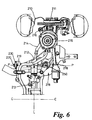
- Figure 6 is a plan view of the suspension arrangement shown in Figure 5.
-
- With reference to Figs. 1 and 2 there is shown a vehicle suspension arrangement for a
steerable road wheel 10 of a motor vehicle. The motor vehicle has a body structure (not shown) extending along a longitudinal axis C-C from a front end to a rear end of the motor vehicle. - The suspension arrangement includes a
steering knuckle 11 for rotatably supporting theroad wheel 10, asuspension arm 12 pivotably connecting thesteering knuckle 11 to part of the body structure, a substantially vertical McPhersontype suspension strut 15 pivotably connected at a lower end thereof by means of apivot joints 8 to thesteering knuckle 11 and a steering actuator in the form of asteering rack 13 for providing a steering input to thesteering knuckle 11 to produce rotation of thesteering knuckle 11 about a steering axis of the motor vehicle. - The
steering rack 13 has a horizontal longitudinal axis L-L that is arranged transversely with respect to the motor vehicle and is substantially at right angles to the longitudinal axis C-C of the motor vehicle. - The
steering rack 13 is connected to thesteering knuckle 11 by atie rod 14. Thetie rod 14 is connected at its outer end to thesteering knuckle 11 by means of aball joint 16. - The
suspension arm 12 is pivotably connected at two spacedapart positions suspension arm 12 is pivotably connected at an outer end thereof by means of aball joint 17 to a lower end of thesteering knuckle 11. - A first of said two spaced apart positions is defined by a
bush 18 and a second of said spaced apart positions is defined by aspigot 20 that co-operates with abush 19 supported by part of the body structure of the motor vehicle. - The outer end of the
suspension arm 12 has a cup-shaped cavity formed therein to support a part-spherical head of theball joint 17. - The
strut 15 has aspring 15a anddamper unit 15b and is resiliently connected at an upper end thereof to part of the body structure by means of anupper spring support 7. - The
suspension arm 12 is a planar member and has a pivot axis P'-P that lies on the plane of thesuspension arm 12. That is to say the pivot axis P'-P extends through the centre of thebush 18 and thespigot 20. - It will be appreciated that if the vertical displacement between the pivot axis P'-P and the longitudinal axis L-L is reduced below a certain amount the
tie rod 14 will foul the upper surface of thesuspension arm 12. - In Figs. 3 and 4 there is shown a vehicle suspension arrangement for a
steerable road wheel 110 of a motor vehicle according to a first embodiment of the invention. - The motor vehicle has a body structure (not shown) extending along a longitudinal axis C-C from a front end to a rear end of the motor vehicle.
- The suspension arrangement includes a
steering knuckle 111 for rotatably supporting theroad wheel 110, asuspension arm 112 pivotably connecting thesteering knuckle 111 to part of the body structure, a substantiallyvertical suspension strut 115 pivotably connected at a lower end thereof by means of twopivot joints steering knuckle 111 and a steering actuator in the form of asteering rack 113 for providing a steering input to thesteering knuckle 111 to produce rotation of thesteering knuckle 111 about the steering axis of the motor vehicle. - The
steering rack 113 has a substantially horizontal longitudinal axis L-L that is arranged transversely with respect to the motor vehicle and is substantially at right angles to the longitudinal axis C-C of the motor vehicle. - The
steering rack 113 is connected to thesteering knuckle 111 by atie rod 114. Thetie rod 114 is connected at its outer end to thesteering knuckle 111 by means of aball joint 116. - The
suspension arm 112 is pivotably connected at two spacedapart positions ball joint 117 to a lower end of thesteering knuckle 111. - A first of said two spaced apart positions, closer to the front of the vehicle, is defined by a ball joint 50, and a second of said spaced apart positions, the rear one, is defined by a
spigot 120 that co-operates with abush 19 supported by part of thebody structure 78 of the motor vehicle. - The outer end of the
suspension arm 112 has a cup-shaped cavity 121 formed therein to support a part-spherical head of theball joint 117. - The ball joint 50 has a part-
spherical head portion 51 pivotably engaged with a cup (not shown) supported by thebody structure 78 and ashank portion 52 secured at one end in atapered aperture 100 in thesuspension arm 112. Theshank 52 is tapered to fit theaperture 100 and is held in place by anut 53. - The length of the
shank portion 52 determines the offset at that position between the pivot axis P'-P of thesuspension arm 112 and the plane P-T-S of thesuspension arm 112. - The pivot axis P'-P of the
suspension arm 112 therefore lies outside the plane P-T-S and is offset upwardly therefrom, at least over the area of the suspension arm, so as to lie closer to the longitudinal axis L-L of thesteering rack 113. The pivot axis P'-P of thesuspension arm 112 also intersects the plane P-T-S at theposition 119 of the rear suspension arm mounting 120. - As can best be seen in Fig. 3 the pivot axis P'-P is inclined with respect to the plane P-T-S of the
suspension arm 112. The inclination of the pivot axis P'-P of thesuspension arm 112 to the plane P-T-S is dependant upon the length of theshank portion 52 of the ball joint 50 and the distance between the two spaced apart positions. - The distance between the pivot axis P'-P and the longitudinal axis L-L is shown by the arrow X on Fig. 3 and the distance between the plane P-T-S and the longitudinal axis L-L is shown by the arrow Y on Fig. 3.
- It will be appreciated that by offsetting the pivot axis P'-P of the
suspension arm 112 from the plane P-T-S of thesuspension arm 112 in this manner it is possible to arrange for thesteering rack 113 to be positioned closer to the pivot axis P'-P of the suspension arm without interference between thetie rod 114 and thesuspension arm 112. - It will be appreciated that Fig. 3 shows only one suspension arrangement and that there would be a similar suspension arrangement for the steerable wheel on the other side of the motor vehicle.
- In Figs. 5 and 6 there is shown a vehicle suspension arrangement for a
steerable road wheel 210 of a motor vehicle according to a second embodiment of the invention. The motor vehicle has a body structure (not shown) extending along a longitudinal axis C-C from a front end to a rear end of the motor vehicle. - The suspension arrangement includes a
steering knuckle 211 for rotatably supporting theroad wheel 210, asuspension arm 212 pivotably connecting thesteering knuckle 211 to part of thebody structure 218. A substantiallyvertical suspension strut 215 is pivotably connected at a lower end thereof to thesteering knuckle 211 and a steering actuator in the form of asteering rack 213 for providing a steering input to thesteering knuckle 211 to produce rotation of thesteering knuckle 211 about a steering axis of the motor vehicle. - The
steering rack 213 has a longitudinal axis L-L that is arranged transversely with respect to the motor vehicle and is substantially at right angles to the longitudinal axis C-C of the motor vehicle. - The
steering rack 213 is connected to thesteering knuckle 211 by atie rod 214. Thetie rod 214 is connected at its outer end to thesteering knuckle 211 by means of aball joint 216. - The
suspension arm 212 is pivotably connected at two spacedapart positions suspension arm 212 is pivotably connected at an outer end thereof by means of a ball joint 217 to a lower end of thesteering knuckle 211. - A first of said two spaced apart positions is defined by a ball joint 250 and a second of said spaced apart positions is defined by a
spigot 220 that co-operates with acompliance bush 230 supported by part of thebody structure 278 of the motor vehicle. - The outer end of the
suspension arm 212 has alug 221 formed thereon to support ashank 222 of the ball joint 217. Anut 223 is used to hold the ball joint 217 in place. - The ball joint 250 has a part-spherical head portion pivotably engaged with a cup-shaped
cavity 254 in thebody structure 278 and ashank portion 252 secured at one end in atapered aperture 200 in thesuspension arm 212. Theshank 252 is tapered to fit theaperture 200 and is held in place by anut 253. - The length of the
shank portion 252 of the ball joint 250 determines the offset "O" at that position between the pivot axis P'-P of thesuspension arm 112 and the plane P-Y of thesuspension arm 212. - The pivot axis P'-P of the
suspension arm 112 therefore lies outside the plane P-Y and is offset upwardly therefrom so as to lie closer to the longitudinal axis L-L of thesteering rack 213. - The distance of the pivot axis P'-P from the longitudinal axis L-L is shown by the arrows Z1 on Fig. 5 and the distance of the plane P-Y from the longitudinal axis L-L can be seen to be a further distance Z2 from this axis.
- As can best be seen in Fig. 5 the pivot axis P'-P is inclined with respect to the plane P-Y of the
suspension arm 212. The inclination of the pivot axis P'-P of the suspension arm to the plane P-Y of the suspension arm is dependant upon the length of theshank portion 252 of the ball joint 250 and the distance between the two spaced apart positions. - It will be appreciated that by offsetting the pivot axis P'-P of the
suspension arm 212 from the plane P-Y of thesuspension arm 212 in this manner it is possible to arrange for the pivot axis P'-P of thesuspension arm 212 to be positioned closer to the longitudinal axis L-L without interference from thetie rod 214. - It will be appreciated that Figs. 5 and 6 show only one suspension arrangement and that there would be a similar suspension arrangement for the steerable wheel on the other side of the motor vehicle.
Claims (11)
- A suspension for a steerable road wheel (110) of a vehicle comprising a steering knuckle (111) rotatable about a steering axis to allow steering of the wheel, a suspension arm (112) having connection means (50, 120) at two spaced apart positions (118, 119) at an inner end thereof for pivotably connecting the suspension arm to a sprung part (78) of the vehicle such that it can rotate about a pivot axis (P'-P) that is substantially parallel to the longitudinal axis (C-C) of the vehicle, and being pivotably connected at an outer end thereof to a lower end of the steering knuckle (111), and a substantially vertical suspension strut (115) pivotably connected at a lower end thereof to the steering knuckle (111) and connected at an upper end thereof to said sprung part (78), characterized in that the suspension arm (112) is a substantially planar member and its pivot axis (P'-P) lies outside its plane (PTS).
- A suspension as claimed in claim 1 in which the plane (PTS) of the suspension arm (112) is inclined to the pivot axis (P'-P) of the suspension arm.
- A suspension as claimed in claim 1 or claim 2 in which one of said connection means comprises a ball joint (50).
- A suspension as claimed in claim 3 in which the ball joint (50) has a part-spherical head portion (51) pivotably engaged with a cup supported by the body structure (78) and a shank portion (52) supporting the part-spherical portion out of the plane (PTS) of the suspension arm.
- A suspension as claimed in claim 4 in which the shank portion (51) extends substantially perpendicular to the plane (PTS) of the suspension arm (112).
- A suspension as claimed in claim 4 or claim 5 in which the shank portion (51) extends substantially vertically.
- A suspension as claimed in any preceding claim in which the suspension strut (115) is a McPherson strut.
- A vehicle including a suspension as claimed in any foregoing claim and a steering actuator (113, 114) for applying a steering torque to the steering knuckle (111), the steering actuator having a substantially horizontal longitudinal axis (L-L) that extends transversely across the vehicle.
- A vehicle as claimed in claim 8 in which the steering actuator (113, 114) extends over the plane (PTS) of the suspension arm (112).
- A vehicle as claimed in claim 8 or in claim 9 in which the pivot axis (P'-P) of the suspension arm lies above the plane (PTS) of the suspension arm.
- A vehicle as claimed in claim 10 in which the longitudinal axis (L-L) of the steering actuator (113, 114) lies closer to the pivot axis (P'-P) of the suspension arm than it does to the plane (PTS) of the suspension arm.
Applications Claiming Priority (2)
| Application Number | Priority Date | Filing Date | Title |
|---|---|---|---|
| GB9902598 | 1999-02-06 | ||
| GBGB9902598.3A GB9902598D0 (en) | 1999-02-06 | 1999-02-06 | A suspension arrangement |
Publications (3)
| Publication Number | Publication Date |
|---|---|
| EP1026018A2 true EP1026018A2 (en) | 2000-08-09 |
| EP1026018A3 EP1026018A3 (en) | 2003-12-17 |
| EP1026018B1 EP1026018B1 (en) | 2007-11-14 |
Family
ID=10847184
Family Applications (1)
| Application Number | Title | Priority Date | Filing Date |
|---|---|---|---|
| EP00300240A Expired - Lifetime EP1026018B1 (en) | 1999-02-06 | 2000-01-14 | A suspension arrangement for a motor vehicle |
Country Status (5)
| Country | Link |
|---|---|
| US (1) | US6231062B1 (en) |
| EP (1) | EP1026018B1 (en) |
| DE (1) | DE60037053T2 (en) |
| ES (1) | ES2293886T3 (en) |
| GB (2) | GB9902598D0 (en) |
Cited By (1)
| Publication number | Priority date | Publication date | Assignee | Title |
|---|---|---|---|---|
| CN104675499A (en) * | 2013-11-27 | 2015-06-03 | 现代自动车株式会社 | Apparatus For Circulating Coolant In Turbocharger |
Families Citing this family (13)
| Publication number | Priority date | Publication date | Assignee | Title |
|---|---|---|---|---|
| KR100503272B1 (en) | 2002-03-07 | 2005-07-25 | 기아자동차주식회사 | Vehicle suspension |
| KR100457316B1 (en) * | 2002-09-05 | 2004-11-16 | 현대자동차주식회사 | Front whell suspension system using steering gear frame |
| US6997467B2 (en) * | 2003-01-23 | 2006-02-14 | Arvin Technologies, Inc. | Reconfigurable strut assembly |
| DE102004034580A1 (en) * | 2004-07-16 | 2006-02-02 | Dr.Ing.H.C. F. Porsche Ag | Support for a control arm for motor vehicles |
| US7776084B2 (en) * | 2005-07-13 | 2010-08-17 | Edwards Lifesciences Corporation | Prosthetic mitral heart valve having a contoured sewing ring |
| DE602006020730D1 (en) * | 2005-07-18 | 2011-04-28 | Magna Int Inc | CONTROL ARM AND AXLE SHAFT ASSEMBLY |
| US8033557B2 (en) * | 2006-10-10 | 2011-10-11 | Honda Motor Co., Ltd. | Vehicle suspension system and method |
| ES2539519T3 (en) * | 2007-07-05 | 2015-07-01 | Ajh Queensland Pty Ltd. | Vehicle suspension system |
| US8985604B2 (en) * | 2010-07-07 | 2015-03-24 | Ford Global Technologies, Llc | Cross axis joint with elastomeric isolation |
| DE102014207793B4 (en) * | 2014-04-25 | 2021-03-04 | Ford Global Technologies, Llc | Wheel suspension for a vehicle |
| WO2020102478A2 (en) * | 2018-11-14 | 2020-05-22 | Magna International Inc. | Modular vehicle architecture enabling range on demand |
| US11364757B2 (en) | 2019-06-28 | 2022-06-21 | Ree Automotive Ltd | Device and method for double-arm suspension and in-wheel steering |
| EP4096942A4 (en) | 2020-01-28 | 2024-04-17 | Ree Automotive Ltd | OFF-CENTER ARM SUSPENSION |
Citations (1)
| Publication number | Priority date | Publication date | Assignee | Title |
|---|---|---|---|---|
| EP0572041A1 (en) | 1989-06-13 | 1993-12-01 | Toyota Jidosha Kabushiki Kaisha | Suspension for steerable driving wheel in vehicle |
Family Cites Families (7)
| Publication number | Priority date | Publication date | Assignee | Title |
|---|---|---|---|---|
| DE75020C (en) * | H. C. HUNTER in Alameda, Californien | Containers for packing dry goods | ||
| GB814666A (en) * | 1956-03-20 | 1959-06-10 | Howard Clawton Wright Ltd | A new or improved ball joint |
| US4715615A (en) * | 1983-07-27 | 1987-12-29 | Mazda Motor Corporation | Vehicle rear-suspension system |
| JPH0625362Y2 (en) * | 1987-10-23 | 1994-07-06 | トヨタ自動車株式会社 | Alignment adjustment device for vehicle suspension |
| DE4137446A1 (en) * | 1990-11-26 | 1992-05-27 | Volkswagen Ag | Suspension for steerable wheels of vehicle - includes suspended mass to eliminate wobble effects |
| DE4330103C2 (en) * | 1992-09-22 | 1998-09-10 | Suzuki Motor Co | Suspension arm for the suspension of a motor vehicle |
| IT1289745B1 (en) * | 1996-12-13 | 1998-10-16 | Fiat Ricerche | REAR SUSPENSION OF VEHICLE |
-
1999
- 1999-02-06 GB GBGB9902598.3A patent/GB9902598D0/en not_active Ceased
-
2000
- 2000-01-13 GB GB0000633A patent/GB2346345A/en not_active Withdrawn
- 2000-01-14 ES ES00300240T patent/ES2293886T3/en not_active Expired - Lifetime
- 2000-01-14 EP EP00300240A patent/EP1026018B1/en not_active Expired - Lifetime
- 2000-01-14 DE DE60037053T patent/DE60037053T2/en not_active Expired - Lifetime
- 2000-01-24 US US09/489,794 patent/US6231062B1/en not_active Expired - Lifetime
Patent Citations (1)
| Publication number | Priority date | Publication date | Assignee | Title |
|---|---|---|---|---|
| EP0572041A1 (en) | 1989-06-13 | 1993-12-01 | Toyota Jidosha Kabushiki Kaisha | Suspension for steerable driving wheel in vehicle |
Cited By (2)
| Publication number | Priority date | Publication date | Assignee | Title |
|---|---|---|---|---|
| CN104675499A (en) * | 2013-11-27 | 2015-06-03 | 现代自动车株式会社 | Apparatus For Circulating Coolant In Turbocharger |
| CN104675499B (en) * | 2013-11-27 | 2018-10-02 | 现代自动车株式会社 | Device for circulating in the coolant in turbocharger |
Also Published As
| Publication number | Publication date |
|---|---|
| DE60037053T2 (en) | 2008-03-13 |
| GB2346345A (en) | 2000-08-09 |
| US6231062B1 (en) | 2001-05-15 |
| DE60037053D1 (en) | 2007-12-27 |
| EP1026018B1 (en) | 2007-11-14 |
| ES2293886T3 (en) | 2008-04-01 |
| GB0000633D0 (en) | 2000-03-01 |
| EP1026018A3 (en) | 2003-12-17 |
| GB9902598D0 (en) | 1999-03-24 |
Similar Documents
| Publication | Publication Date | Title |
|---|---|---|
| EP1026018B1 (en) | A suspension arrangement for a motor vehicle | |
| US5346241A (en) | Vehicle suspension system for a steerable wheel | |
| US5797618A (en) | Spring strut for a front wheel suspension of the McPherson type for motor vehicles | |
| EP3218211B1 (en) | Wheel suspension with centrally pivoted transverse leaf spring | |
| US5558360A (en) | Vehicle suspension system for a steerable drive wheel | |
| KR100335952B1 (en) | Front suspension assembly of cars | |
| CA1191163A (en) | Independent wheel suspension for motor vehicles | |
| US5979919A (en) | Independent wheel suspension for steered wheels of passenger motor vehicles and the like | |
| US6997468B2 (en) | Control rod suspension with outboard shock | |
| JPS5852846B2 (en) | suspension system | |
| US5374076A (en) | Vehicle suspension system for a steerable wheel | |
| US5158320A (en) | Suspension system for vehicles | |
| US6471224B1 (en) | Kingpin independent front suspension | |
| JP2513699B2 (en) | Rear suspension | |
| US5094474A (en) | Suspension system for a vehicle | |
| JPH0143283Y2 (en) | ||
| US20080303237A1 (en) | Idividual Wheel Suspension | |
| JP3200854B2 (en) | Method of assembling steering wheel suspension | |
| JP2761044B2 (en) | Vehicle suspension device | |
| JP2001113923A (en) | Double wishbone suspension | |
| JP3664353B2 (en) | Vehicle suspension system | |
| JP3105073B2 (en) | Vehicle suspension device | |
| JPH0451050Y2 (en) | ||
| KR100207104B1 (en) | Steering wheel suspension for automobile | |
| JPH0224321Y2 (en) |
Legal Events
| Date | Code | Title | Description |
|---|---|---|---|
| PUAI | Public reference made under article 153(3) epc to a published international application that has entered the european phase |
Free format text: ORIGINAL CODE: 0009012 |
|
| AK | Designated contracting states |
Kind code of ref document: A2 Designated state(s): AT BE CH CY DE DK ES FI FR GB GR IE IT LI LU MC NL PT SE |
|
| AX | Request for extension of the european patent |
Free format text: AL;LT;LV;MK;RO;SI |
|
| RAP1 | Party data changed (applicant data changed or rights of an application transferred) |
Owner name: BAYERISCHE MOTOREN WERKE AKTIENGESELLSCHAFT |
|
| PUAL | Search report despatched |
Free format text: ORIGINAL CODE: 0009013 |
|
| AK | Designated contracting states |
Kind code of ref document: A3 Designated state(s): AT BE CH CY DE DK ES FI FR GB GR IE IT LI LU MC NL PT SE |
|
| AX | Request for extension of the european patent |
Extension state: AL LT LV MK RO SI |
|
| 17P | Request for examination filed |
Effective date: 20040129 |
|
| AKX | Designation fees paid |
Designated state(s): DE ES FR GB IT |
|
| GRAP | Despatch of communication of intention to grant a patent |
Free format text: ORIGINAL CODE: EPIDOSNIGR1 |
|
| GRAS | Grant fee paid |
Free format text: ORIGINAL CODE: EPIDOSNIGR3 |
|
| GRAA | (expected) grant |
Free format text: ORIGINAL CODE: 0009210 |
|
| AK | Designated contracting states |
Kind code of ref document: B1 Designated state(s): DE ES FR GB IT |
|
| REG | Reference to a national code |
Ref country code: GB Ref legal event code: FG4D |
|
| REF | Corresponds to: |
Ref document number: 60037053 Country of ref document: DE Date of ref document: 20071227 Kind code of ref document: P |
|
| REG | Reference to a national code |
Ref country code: ES Ref legal event code: FG2A Ref document number: 2293886 Country of ref document: ES Kind code of ref document: T3 |
|
| ET | Fr: translation filed | ||
| PLBE | No opposition filed within time limit |
Free format text: ORIGINAL CODE: 0009261 |
|
| STAA | Information on the status of an ep patent application or granted ep patent |
Free format text: STATUS: NO OPPOSITION FILED WITHIN TIME LIMIT |
|
| 26N | No opposition filed |
Effective date: 20080815 |
|
| REG | Reference to a national code |
Ref country code: FR Ref legal event code: PLFP Year of fee payment: 17 |
|
| REG | Reference to a national code |
Ref country code: FR Ref legal event code: PLFP Year of fee payment: 18 |
|
| PGFP | Annual fee paid to national office [announced via postgrant information from national office to epo] |
Ref country code: FR Payment date: 20170124 Year of fee payment: 18 Ref country code: DE Payment date: 20170121 Year of fee payment: 18 |
|
| PGFP | Annual fee paid to national office [announced via postgrant information from national office to epo] |
Ref country code: GB Payment date: 20170125 Year of fee payment: 18 |
|
| PGFP | Annual fee paid to national office [announced via postgrant information from national office to epo] |
Ref country code: ES Payment date: 20170124 Year of fee payment: 18 Ref country code: IT Payment date: 20170125 Year of fee payment: 18 |
|
| REG | Reference to a national code |
Ref country code: DE Ref legal event code: R119 Ref document number: 60037053 Country of ref document: DE |
|
| GBPC | Gb: european patent ceased through non-payment of renewal fee |
Effective date: 20180114 |
|
| PG25 | Lapsed in a contracting state [announced via postgrant information from national office to epo] |
Ref country code: FR Free format text: LAPSE BECAUSE OF NON-PAYMENT OF DUE FEES Effective date: 20180131 Ref country code: DE Free format text: LAPSE BECAUSE OF NON-PAYMENT OF DUE FEES Effective date: 20180801 |
|
| REG | Reference to a national code |
Ref country code: FR Ref legal event code: ST Effective date: 20180928 |
|
| PG25 | Lapsed in a contracting state [announced via postgrant information from national office to epo] |
Ref country code: GB Free format text: LAPSE BECAUSE OF NON-PAYMENT OF DUE FEES Effective date: 20180114 |
|
| PG25 | Lapsed in a contracting state [announced via postgrant information from national office to epo] |
Ref country code: IT Free format text: LAPSE BECAUSE OF NON-PAYMENT OF DUE FEES Effective date: 20180114 |
|
| REG | Reference to a national code |
Ref country code: ES Ref legal event code: FD2A Effective date: 20190730 |
|
| PG25 | Lapsed in a contracting state [announced via postgrant information from national office to epo] |
Ref country code: ES Free format text: LAPSE BECAUSE OF NON-PAYMENT OF DUE FEES Effective date: 20180115 |