EP1024994B1 - Full floating double action bicycle suspension system - Google Patents
Full floating double action bicycle suspension system Download PDFInfo
- Publication number
- EP1024994B1 EP1024994B1 EP99939556A EP99939556A EP1024994B1 EP 1024994 B1 EP1024994 B1 EP 1024994B1 EP 99939556 A EP99939556 A EP 99939556A EP 99939556 A EP99939556 A EP 99939556A EP 1024994 B1 EP1024994 B1 EP 1024994B1
- Authority
- EP
- European Patent Office
- Prior art keywords
- suspension arm
- suspension
- arm
- main
- connecting link
- Prior art date
- Legal status (The legal status is an assumption and is not a legal conclusion. Google has not performed a legal analysis and makes no representation as to the accuracy of the status listed.)
- Expired - Lifetime
Links
Images


Classifications
-
- B—PERFORMING OPERATIONS; TRANSPORTING
- B62—LAND VEHICLES FOR TRAVELLING OTHERWISE THAN ON RAILS
- B62K—CYCLES; CYCLE FRAMES; CYCLE STEERING DEVICES; RIDER-OPERATED TERMINAL CONTROLS SPECIALLY ADAPTED FOR CYCLES; CYCLE AXLE SUSPENSIONS; CYCLE SIDE-CARS, FORECARS, OR THE LIKE
- B62K19/00—Cycle frames
- B62K19/30—Frame parts shaped to receive other cycle parts or accessories
- B62K19/34—Bottom brackets
-
- B—PERFORMING OPERATIONS; TRANSPORTING
- B62—LAND VEHICLES FOR TRAVELLING OTHERWISE THAN ON RAILS
- B62K—CYCLES; CYCLE FRAMES; CYCLE STEERING DEVICES; RIDER-OPERATED TERMINAL CONTROLS SPECIALLY ADAPTED FOR CYCLES; CYCLE AXLE SUSPENSIONS; CYCLE SIDE-CARS, FORECARS, OR THE LIKE
- B62K25/00—Axle suspensions
- B62K25/04—Axle suspensions for mounting axles resiliently on cycle frame or fork
- B62K25/28—Axle suspensions for mounting axles resiliently on cycle frame or fork with pivoted chain-stay
- B62K25/286—Axle suspensions for mounting axles resiliently on cycle frame or fork with pivoted chain-stay the shock absorber being connected to the chain-stay via a linkage mechanism
Definitions
- the present invention is directed to a suspension system that is particularly useful for the off-road bicycles better known as mountain bikes.
- the pivot point of many suspension units has been raised above the large drivetrain ring, or bottom bracket, or the pivot and rear axle have been placed on the same moving frame, usually called the unified rear arm.
- the present invention is directed to a suspension system which, in addition to the main suspension arm that holds the rear wheel, includes a secondary smaller arm under the main one.
- the two arms are connected through a straight, connecting link.
- the shock absorber is located between the two arms.
- the present invention aims to overcome the problems arising in most of the existing designs, such as the biopacing ("sinking") effect on the pedaling movement; the chain drag due to the chain force pulling the suspension in further compression; the unwanted compression when the bike is climbing steep terrain; and the difficulty of fine tuning the front derailleur due to the movement of the drivetrain discs.
- This is achieved by placing the bottom bracket axle on an independent arm, the secondary arm, which moves in conjunction with the main suspension arm.
- the full floating double action bicycle suspension system (the present invention) has certain advantages, such as the option of pretuning suspension travel in six different ways, the ability to increase or reduce the suspension rate drastically by changing the rider's position; the elimination of the acceleration-created "sag”; the elimination of the biopacing effect; and the complete alignment of the front derailleur with the drivetrain discs.
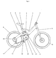
- FIG 1 a bicycle is shown in which the front suspension mechanism (fork) (6) is connected to the main frame (1).
- the steering bar (7) is attached to the top of the fork.
- the front wheel (10) is attached to the bottom of the fork.
- the saddle (8) is attached to the rear of the main frame.
- the main suspension arm (2) is under the saddle.
- Behind the main suspension arm is the rear wheel (9) which is attached to the cassette (56) and the rear derailleur (12).
- Under the main suspension arm is the secondary suspension arm (4) to which the drivetrain discs (41) are attached, as are the pedals (42) and the pedal axle (13).
- the main suspension arm is connected to the secondary suspension by the connecting link (3).
- the shock absorber (5) is located between the two arms.
- the transmission chain (14) is located between the drivetrain discs (41) and the cassette (56).
- FIGS 2, 3 and 4 show a more detailed view of the main frame (1).
- the main suspension arm (2) and the secondary suspension arm (4) are also attached to the rear of the main frame.
- the front end of the main suspension arm (2) is attached to the frame (1) by a pivot (26), the pivot's roller bearings (34, 54) and the roller bearing mount (55).
- the dropouts (15) hold the rear wheel (9).
- Under the main suspension arm (2) is the secondary suspension arm (4).
- the front end of the secondary suspension arm (4) is attached to the frame (1) by a pivot (16), the pivot's roller bearings (43, 44) and the roller bearing mount (45).
- the bottom bracket tube (57) containing the bottom bracket axle (13) is attached to the rear end of the secondary suspension arm.
- the main suspension arm (2) is connected to the secondary suspension arm (4) by the connecting link (3).
- the upper end of the connecting link (3) is attached to the main suspension arm (4) by a pivot (30), the pivot's roller bearings (32, 33) and the roller bearing mount (31 or 34).
- the lower end of the connecting link is attached to the secondary suspension arm (4) by the bottom bracket tube (57), the bottom bracket tube roller bearings (23, 24) and the roller bearing mount (25).
- the bottom bracket tube (57) also functions as a pivot attaching the connecting link (3) to the secondary suspension arm (4).
- the shock absorber (5) is located between the suspension parts (2, 3, 4) and the main frame (1).
- the upper end of the shock absorber (5) is attached to the shock mount (35) of the main suspension arm.
- the lower end of the shock absorber is attached to one of the three optional positions (20, 21, 22) of the secondary suspension arm (4).
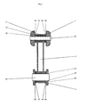
- FIG. 5 shows a cutout of the front view of connecting link (3), one part of the main suspension arm (2), and the secondary suspension arm (4).
- the upper end of the connecting link (3) is attached to the main suspension arm (2) by a pivot (30), the pivot's roller bearings (32, 33), the pivot's side sliders (50, 51, 52, 53) and the roller bearing mount (31).
- the lower end of the connecting link is attached to the secondary suspension arm (4) by the bottom bracket tube (57), the bottom bracket tube roller bearings (23, 24), the pivot's side sliders (46, 47, 48, 49) and the roller bearing mount (25).
- the secondary suspension arm (2) pulls the connecting link (3) which in turn pulls the secondary suspension arm (4) upward.
- the main suspension arm's shock mount (35) which moves downwards and the secondary suspension arm (4) which moves upward we have compression (or extension if the arms are moving in the opposite direction) of a full floating shock by double action because both arms are moving, unlike the traditional designs in which one end of the shock absorber is attached to the frame.
- This design offers six basic suspension adjustments: Three optical positions (20, 21, 22) for the shock absorber (5) located on the secondary suspension arm (4), combined with the two optional positions of the connecting link (3). These adjustments, together with shock compression and rebound adjustments, offer a wide variety of suspension behavior, without compromising the performance of the front derailleur (40).
Abstract
Description
- The present invention is directed to a suspension system that is particularly useful for the off-road bicycles better known as mountain bikes.
- The use of full suspension bikes is widespread in all-terrain (mountain) biking and especially in downhill racing.
- In most rear wheel suspension systems on all-terrain bicycles, depending on the design, a number of problems arise such as: the biopacing effect, where the forces produced by the pedaling effort tend to pull the rear suspension making it sink periodically following the pedaling movement; the chain drag when the rear axle goes above the pivot point, and the chain tends to pull the suspension in further compression; the unwanted compression of the rear system when the bike is climbing on steep terrain, and the center of gravity moves backward, overloading the rear of the bike, exaggerating the suspension; and the difficulty of fine tuning the front derailleur owing to the movement of the drivetrain discs.
- To overcome these problems, the pivot point of many suspension units has been raised above the large drivetrain ring, or bottom bracket, or the pivot and rear axle have been placed on the same moving frame, usually called the unified rear arm.
- Although some of these problems have been solved in various designs, most full suspension bikes are used only in the downhill competition field.
- The present invention is directed to a suspension system which, in addition to the main suspension arm that holds the rear wheel, includes a secondary smaller arm under the main one. The two arms are connected through a straight, connecting link. The shock absorber is located between the two arms.
- The present invention aims to overcome the problems arising in most of the existing designs, such as the biopacing ("sinking") effect on the pedaling movement; the chain drag due to the chain force pulling the suspension in further compression; the unwanted compression when the bike is climbing steep terrain; and the difficulty of fine tuning the front derailleur due to the movement of the drivetrain discs. This is achieved by placing the bottom bracket axle on an independent arm, the secondary arm, which moves in conjunction with the main suspension arm.
- Looking at the plans, we can see that the full floating double action bicycle suspension system (the present invention) has certain advantages, such as the option of pretuning suspension travel in six different ways, the ability to increase or reduce the suspension rate drastically by changing the rider's position; the elimination of the acceleration-created "sag"; the elimination of the biopacing effect; and the complete alignment of the front derailleur with the drivetrain discs.
- The present invention is described in the following drawings:
- FIG. 1. This is a side view of a bicycle with a full floating double action bicycle suspension system; a front suspension system; wheels; and a full transmission system.
- FIG. 2 This is a side view of the main frame with the rear suspension system.
- FIG. 3. This is a cutout of the side view of the main frame with the rear suspension system.
- FIG. 4. This is an enlargement of the cutout side view of the main frame with the rear suspension system.
- FIG. 5. This is a cutout of the front view of the connecting link.
- In FIG 1 a bicycle is shown in which the front suspension mechanism (fork) (6) is connected to the main frame (1). The steering bar (7) is attached to the top of the fork. The front wheel (10) is attached to the bottom of the fork. The saddle (8) is attached to the rear of the main frame. The main suspension arm (2) is under the saddle. Behind the main suspension arm is the rear wheel (9) which is attached to the cassette (56) and the rear derailleur (12). Under the main suspension arm is the secondary suspension arm (4) to which the drivetrain discs (41) are attached, as are the pedals (42) and the pedal axle (13). The main suspension arm is connected to the secondary suspension by the connecting link (3). The shock absorber (5) is located between the two arms. The transmission chain (14) is located between the drivetrain discs (41) and the cassette (56).
- FIGS 2, 3 and 4 show a more detailed view of the main frame (1). At the front of the main frame is the steerer tube roller bearing mount (36), while in the rear is the seatmast mount (37) and close (38). The main suspension arm (2) and the secondary suspension arm (4) are also attached to the rear of the main frame. The front end of the main suspension arm (2) is attached to the frame (1) by a pivot (26), the pivot's roller bearings (34, 54) and the roller bearing mount (55). At the rear end, the dropouts (15) hold the rear wheel (9). Under the main suspension arm (2) is the secondary suspension arm (4). The front end of the secondary suspension arm (4) is attached to the frame (1) by a pivot (16), the pivot's roller bearings (43, 44) and the roller bearing mount (45). The bottom bracket tube (57) containing the bottom bracket axle (13) is attached to the rear end of the secondary suspension arm. The main suspension arm (2) is connected to the secondary suspension arm (4) by the connecting link (3). The upper end of the connecting link (3) is attached to the main suspension arm (4) by a pivot (30), the pivot's roller bearings (32, 33) and the roller bearing mount (31 or 34). The lower end of the connecting link is attached to the secondary suspension arm (4) by the bottom bracket tube (57), the bottom bracket tube roller bearings (23, 24) and the roller bearing mount (25). The bottom bracket tube (57) also functions as a pivot attaching the connecting link (3) to the secondary suspension arm (4). The shock absorber (5) is located between the suspension parts (2, 3, 4) and the main frame (1). The upper end of the shock absorber (5) is attached to the shock mount (35) of the main suspension arm. The lower end of the shock absorber is attached to one of the three optional positions (20, 21, 22) of the secondary suspension arm (4).
- FIG. 5 shows a cutout of the front view of connecting link (3), one part of the main suspension arm (2), and the secondary suspension arm (4). The upper end of the connecting link (3) is attached to the main suspension arm (2) by a pivot (30), the pivot's roller bearings (32, 33), the pivot's side sliders (50, 51, 52, 53) and the roller bearing mount (31). The lower end of the connecting link is attached to the secondary suspension arm (4) by the bottom bracket tube (57), the bottom bracket tube roller bearings (23, 24), the pivot's side sliders (46, 47, 48, 49) and the roller bearing mount (25).
- When the suspension is activated, the secondary suspension arm (2) pulls the connecting link (3) which in turn pulls the secondary suspension arm (4) upward.
By placing the shock absorber (5) between two opposite moving arms, the main suspension arm's shock mount (35) which moves downwards and the secondary suspension arm (4) which moves upward, we have compression (or extension if the arms are moving in the opposite direction) of a full floating shock by double action because both arms are moving, unlike the traditional designs in which one end of the shock absorber is attached to the frame. - The upward movement of the secondary suspension arm (4) compresses the shock absorber (5) more than the downward movement of the main suspension arm's shock mount (35). By compressing the shock absorber (5) in this order, the suspension system gains the following advantages:
- A) The ability to pretune suspension travel. The ability to choose one of the three different shock mounts (20, 21, 22) makes it possible for the secondary suspension arm (4) to deliver a different torque to the shock absorber.
- B) The ability to pretune the main suspension arm torque delivered by the connecting link (3) to the secondary suspension arm. This can be achieved by altering the distance between the upper connecting link pivot and the main suspension arm pivot (26), by choosing one of the two different pivot positions (30, 34).
- C) The ability to increase or reduce the stiffness of the suspension by changing,the rider's position. When pedaling out of the saddle, a style used mainly for climbing steep terrain, the suspension stiffens as the rider's weight is loaded onto the bottom bracket axle (13). This happens because the bottom bracket tube, when bearing the load of the bottom bracket axle, pulls down the secondary suspension arm (4) which in turn pulls the connecting link (3) that finally pulls the main suspension arm (2) toward the ground. This action reduces the load delivered by the main suspension arm (2) to the shock absorber, making the whole system stiffer, and thereby reducing the unwanted "sag" of the rear suspension caused by overloading when climbing.
- D) Elimination of the biopacing effect. Each downward pedal stroke produces torque that stiffens the suspension by pulling the main suspension arm (2) downwards through the system of the connecting link (3) and the secondary suspension arm (4).
- E) Elimination of the unwanted "sag" due to the acceleration of the bike. This is achieved by taking advantage of the pedaling pressure on the system (as in D) and the torque produced by the transmission chain (14) between the drivetrain discs (41) and the rear dropouts (15), to which the rear wheel (9) axle is attached.
- F) Full alignment of the front derailleur with the drivetrain discs during the entire suspension travel.
- This design offers six basic suspension adjustments: Three optical positions (20, 21, 22) for the shock absorber (5) located on the secondary suspension arm (4), combined with the two optional positions of the connecting link (3). These adjustments, together with shock compression and rebound adjustments, offer a wide variety of suspension behavior, without compromising the performance of the front derailleur (40).
Claims (1)
- A bicycle suspension system that, comprising a main suspension arm (2) holding a rear wheel (9), a secondary smaller arm (4) under the main arm (2), the two arms being connected through a straight connecting link (3), a shock absorber (5) being located between the two arms, the suspension system being of the full floating double action type and further comprises a bottom bracket tube (57) which is located on the secondary suspension arm (4) and rotates through a roller bearing system (23, 24, 25, 46, 47, 48, 49) like a pivot to connect the secondary suspension arm (4) to the connecting link (3), which despite being moveable, is in constant alignment to drivetrain discs (41), thus offering full alignment of a front derailleur (40) and the drivetrain discs (41) during the entire suspension travel.
Applications Claiming Priority (3)
| Application Number | Priority Date | Filing Date | Title |
|---|---|---|---|
| GR98100322 | 1998-08-31 | ||
| GR98100322 | 1998-08-31 | ||
| PCT/GR1999/000031 WO2000012376A1 (en) | 1998-08-31 | 1999-08-26 | Full floating double action bicycle suspension system |
Publications (2)
| Publication Number | Publication Date |
|---|---|
| EP1024994A1 EP1024994A1 (en) | 2000-08-09 |
| EP1024994B1 true EP1024994B1 (en) | 2006-11-29 |
Family
ID=10943476
Family Applications (1)
| Application Number | Title | Priority Date | Filing Date |
|---|---|---|---|
| EP99939556A Expired - Lifetime EP1024994B1 (en) | 1998-08-31 | 1999-08-26 | Full floating double action bicycle suspension system |
Country Status (5)
| Country | Link |
|---|---|
| EP (1) | EP1024994B1 (en) |
| AT (1) | ATE346787T1 (en) |
| DE (1) | DE69934203D1 (en) |
| GR (1) | GR1003204B (en) |
| WO (1) | WO2000012376A1 (en) |
Families Citing this family (6)
| Publication number | Priority date | Publication date | Assignee | Title |
|---|---|---|---|---|
| DE19959795C2 (en) * | 1999-12-07 | 2002-01-17 | Andreas Horeld | Frame suspension system for bicycles |
| JP3768788B2 (en) * | 2000-09-05 | 2006-04-19 | 本田技研工業株式会社 | Vehicle swing arm suspension system |
| JP4627370B2 (en) | 2001-01-10 | 2011-02-09 | 本田技研工業株式会社 | Body frame structure for motorcycles |
| DE10110709B4 (en) * | 2001-03-06 | 2007-11-08 | Centurion Renner Kg | bicycle frame |
| WO2005073064A1 (en) * | 2004-01-29 | 2005-08-11 | Michael Roydon Puzey | Vehicle and vehicle suspension system |
| SK6148Y1 (en) * | 2011-08-22 | 2012-06-04 | Boris Hudak | Bike with modifiable design to climb, descent and terrain roughness |
Family Cites Families (6)
| Publication number | Priority date | Publication date | Assignee | Title |
|---|---|---|---|---|
| US5452910A (en) * | 1994-09-09 | 1995-09-26 | Rockshox, Inc. | Rear wheel suspension for a bicycle and bicycle equipped therewith |
| DE4435482A1 (en) * | 1994-10-04 | 1996-04-11 | Harald Kutzke | Rear wheel suspension for bicycle or motorcycle |
| JPH09109974A (en) * | 1995-10-23 | 1997-04-28 | Miyata Ind Co Ltd | Frame for bicycle |
| FR2748446B1 (en) * | 1996-05-13 | 1998-06-26 | Michel Philippe | MONOCOQUE BICYCLE FRAME WITH REAR SUSPENSION AND SWINGARM |
| US5791674A (en) * | 1997-03-13 | 1998-08-11 | Cannondale Corporation | Bicycle suspension system |
| US6073950A (en) * | 1997-10-28 | 2000-06-13 | Busby; James S. | Bicycle with crank assembly suspension system |
-
1998
- 1998-08-31 GR GR980100322A patent/GR1003204B/en not_active IP Right Cessation
-
1999
- 1999-08-26 AT AT99939556T patent/ATE346787T1/en not_active IP Right Cessation
- 1999-08-26 DE DE69934203T patent/DE69934203D1/en not_active Expired - Lifetime
- 1999-08-26 WO PCT/GR1999/000031 patent/WO2000012376A1/en active IP Right Grant
- 1999-08-26 EP EP99939556A patent/EP1024994B1/en not_active Expired - Lifetime
Also Published As
| Publication number | Publication date |
|---|---|
| GR1003204B (en) | 1999-09-03 |
| ATE346787T1 (en) | 2006-12-15 |
| WO2000012376A1 (en) | 2000-03-09 |
| DE69934203D1 (en) | 2007-01-11 |
| EP1024994A1 (en) | 2000-08-09 |
Similar Documents
| Publication | Publication Date | Title |
|---|---|---|
| US7392999B2 (en) | Bicycle with rear suspension | |
| US5899480A (en) | Rear suspension for bicycles | |
| US6880847B2 (en) | Bicycle rear suspension | |
| US10457348B2 (en) | Bicycle rear suspension | |
| US7267351B2 (en) | Frame assembly for a bicycle | |
| US6926298B2 (en) | Bicycle suspension apparatus and related method | |
| US7296815B2 (en) | Bicycle suspension apparatus and related method | |
| EP2420435B1 (en) | Bicycle frame with rear suspension system | |
| US20030038450A1 (en) | Rear suspension system for two-wheeled vehicles, particularly bicycles | |
| US10377442B2 (en) | Suspension for a bicycle | |
| WO1993013974A1 (en) | Rear suspension for bicycles | |
| EP1024994B1 (en) | Full floating double action bicycle suspension system | |
| GB2454021A (en) | Bicycle with rear suspension system | |
| GB2366263A (en) | Bicycle frame | |
| US20210380195A1 (en) | Bicycle rear suspension system with selectable axle paths | |
| WO2023156788A1 (en) | Bicycle frame |
Legal Events
| Date | Code | Title | Description |
|---|---|---|---|
| PUAI | Public reference made under article 153(3) epc to a published international application that has entered the european phase |
Free format text: ORIGINAL CODE: 0009012 |
|
| 17P | Request for examination filed |
Effective date: 20000413 |
|
| AK | Designated contracting states |
Kind code of ref document: A1 Designated state(s): AT BE CH CY DE DK ES FI FR GB GR IE IT LI LU MC NL PT SE |
|
| GRAP | Despatch of communication of intention to grant a patent |
Free format text: ORIGINAL CODE: EPIDOSNIGR1 |
|
| GRAS | Grant fee paid |
Free format text: ORIGINAL CODE: EPIDOSNIGR3 |
|
| GRAA | (expected) grant |
Free format text: ORIGINAL CODE: 0009210 |
|
| AK | Designated contracting states |
Kind code of ref document: B1 Designated state(s): AT BE CH CY DE DK ES FI FR GB GR IE IT LI LU MC NL PT SE |
|
| PG25 | Lapsed in a contracting state [announced via postgrant information from national office to epo] |
Ref country code: NL Free format text: LAPSE BECAUSE OF FAILURE TO SUBMIT A TRANSLATION OF THE DESCRIPTION OR TO PAY THE FEE WITHIN THE PRESCRIBED TIME-LIMIT Effective date: 20061129 Ref country code: LI Free format text: LAPSE BECAUSE OF FAILURE TO SUBMIT A TRANSLATION OF THE DESCRIPTION OR TO PAY THE FEE WITHIN THE PRESCRIBED TIME-LIMIT Effective date: 20061129 Ref country code: IT Free format text: LAPSE BECAUSE OF FAILURE TO SUBMIT A TRANSLATION OF THE DESCRIPTION OR TO PAY THE FEE WITHIN THE PRE;WARNING: LAPSES OF ITALIAN PATENTS WITH EFFECTIVE DATE BEFORE 2007 MAY HAVE OCCURRED AT ANY TIME BEFORE 2007. THE CORRECT EFFECTIVE DATE MAY BE DIFFERENT FROM THE ONE RECORDED.SCRIBED TIME-LIMIT Effective date: 20061129 Ref country code: FI Free format text: LAPSE BECAUSE OF FAILURE TO SUBMIT A TRANSLATION OF THE DESCRIPTION OR TO PAY THE FEE WITHIN THE PRESCRIBED TIME-LIMIT Effective date: 20061129 Ref country code: CH Free format text: LAPSE BECAUSE OF FAILURE TO SUBMIT A TRANSLATION OF THE DESCRIPTION OR TO PAY THE FEE WITHIN THE PRESCRIBED TIME-LIMIT Effective date: 20061129 Ref country code: BE Free format text: LAPSE BECAUSE OF FAILURE TO SUBMIT A TRANSLATION OF THE DESCRIPTION OR TO PAY THE FEE WITHIN THE PRESCRIBED TIME-LIMIT Effective date: 20061129 Ref country code: AT Free format text: LAPSE BECAUSE OF FAILURE TO SUBMIT A TRANSLATION OF THE DESCRIPTION OR TO PAY THE FEE WITHIN THE PRESCRIBED TIME-LIMIT Effective date: 20061129 |
|
| REG | Reference to a national code |
Ref country code: GB Ref legal event code: FG4D |
|
| REG | Reference to a national code |
Ref country code: IE Ref legal event code: FG4D Ref country code: CH Ref legal event code: EP |
|
| REG | Reference to a national code |
Ref country code: IE Ref legal event code: FG4D |
|
| REF | Corresponds to: |
Ref document number: 69934203 Country of ref document: DE Date of ref document: 20070111 Kind code of ref document: P |
|
| PG25 | Lapsed in a contracting state [announced via postgrant information from national office to epo] |
Ref country code: SE Free format text: LAPSE BECAUSE OF FAILURE TO SUBMIT A TRANSLATION OF THE DESCRIPTION OR TO PAY THE FEE WITHIN THE PRESCRIBED TIME-LIMIT Effective date: 20070228 Ref country code: DK Free format text: LAPSE BECAUSE OF FAILURE TO SUBMIT A TRANSLATION OF THE DESCRIPTION OR TO PAY THE FEE WITHIN THE PRESCRIBED TIME-LIMIT Effective date: 20070228 |
|
| PG25 | Lapsed in a contracting state [announced via postgrant information from national office to epo] |
Ref country code: DE Free format text: LAPSE BECAUSE OF FAILURE TO SUBMIT A TRANSLATION OF THE DESCRIPTION OR TO PAY THE FEE WITHIN THE PRESCRIBED TIME-LIMIT Effective date: 20070301 |
|
| PG25 | Lapsed in a contracting state [announced via postgrant information from national office to epo] |
Ref country code: ES Free format text: LAPSE BECAUSE OF FAILURE TO SUBMIT A TRANSLATION OF THE DESCRIPTION OR TO PAY THE FEE WITHIN THE PRESCRIBED TIME-LIMIT Effective date: 20070312 |
|
| PG25 | Lapsed in a contracting state [announced via postgrant information from national office to epo] |
Ref country code: PT Free format text: LAPSE BECAUSE OF FAILURE TO SUBMIT A TRANSLATION OF THE DESCRIPTION OR TO PAY THE FEE WITHIN THE PRESCRIBED TIME-LIMIT Effective date: 20070430 |
|
| NLV1 | Nl: lapsed or annulled due to failure to fulfill the requirements of art. 29p and 29m of the patents act | ||
| REG | Reference to a national code |
Ref country code: CH Ref legal event code: PL |
|
| EN | Fr: translation not filed | ||
| PLBE | No opposition filed within time limit |
Free format text: ORIGINAL CODE: 0009261 |
|
| STAA | Information on the status of an ep patent application or granted ep patent |
Free format text: STATUS: NO OPPOSITION FILED WITHIN TIME LIMIT |
|
| 26N | No opposition filed |
Effective date: 20070830 |
|
| GBPC | Gb: european patent ceased through non-payment of renewal fee |
Effective date: 20070826 |
|
| PG25 | Lapsed in a contracting state [announced via postgrant information from national office to epo] |
Ref country code: MC Free format text: LAPSE BECAUSE OF NON-PAYMENT OF DUE FEES Effective date: 20070831 Ref country code: GR Free format text: LAPSE BECAUSE OF FAILURE TO SUBMIT A TRANSLATION OF THE DESCRIPTION OR TO PAY THE FEE WITHIN THE PRESCRIBED TIME-LIMIT Effective date: 20070301 Ref country code: FR Free format text: LAPSE BECAUSE OF FAILURE TO SUBMIT A TRANSLATION OF THE DESCRIPTION OR TO PAY THE FEE WITHIN THE PRESCRIBED TIME-LIMIT Effective date: 20070720 |
|
| PG25 | Lapsed in a contracting state [announced via postgrant information from national office to epo] |
Ref country code: IE Free format text: LAPSE BECAUSE OF NON-PAYMENT OF DUE FEES Effective date: 20070827 |
|
| PG25 | Lapsed in a contracting state [announced via postgrant information from national office to epo] |
Ref country code: GB Free format text: LAPSE BECAUSE OF NON-PAYMENT OF DUE FEES Effective date: 20070826 Ref country code: FR Free format text: LAPSE BECAUSE OF FAILURE TO SUBMIT A TRANSLATION OF THE DESCRIPTION OR TO PAY THE FEE WITHIN THE PRESCRIBED TIME-LIMIT Effective date: 20061129 |
|
| PG25 | Lapsed in a contracting state [announced via postgrant information from national office to epo] |
Ref country code: LU Free format text: LAPSE BECAUSE OF NON-PAYMENT OF DUE FEES Effective date: 20070826 Ref country code: CY Free format text: LAPSE BECAUSE OF FAILURE TO SUBMIT A TRANSLATION OF THE DESCRIPTION OR TO PAY THE FEE WITHIN THE PRESCRIBED TIME-LIMIT Effective date: 20061129 |