BACKGROUND OF THE INVENTION
The present invention relates to a stored image
regenerating device (or image-information storage
regenerating device), and more particularly to a video
communication system which can collect and store
multiplexed data of audio/video and other information
from video data communication terminals (e. g., visual
telephone sets) according to the recommendation by ITU
(International Telecommunication Union) and allows
users to regenerate the stored data through their
terminal sets, and more particularly to a video data
storage control device for regenerating a video data
file stored in a storing/regenerating center (storage
device) for video data, and more particularly to a
video data regeneration control device which is capable
of transmitting stored coded video data from a video
data storage and regeneration center (storage device)
to an audio-visual (AV) terminal and enabling the
terminal to decode the received coded video data and
reproduce images thereat, and which is also capable of
transmitting stored in itself coded video data to a
receiving terminal and enabling the terminal to decode
the received coded video data and reproduce therefrom
the video data.
Recently, besides conventional interactive
communication services using telephones and facsimiles,
such a communication service has been provided that
audio data stored at a center of communication network
can be always regenerated through users' terminal sets.
On the other hand, with improvement and development of
digital communications networks, e.g., ISDN (Integrated
Services Digital Network), it has been possible to use
video communication services, e.g., visual telephone
service. On such background, there is an increasing
demand for video delivery services using a database of
video information. Such communication services have
been locally realized for practical use.
Recently, with improvement and development of
digital transmission channels and advancement of image
processing technique, it has been expected to develop
a method allowing one to effectively use image-information
services over high-speed digital
transmission networks, a representative of which is
ISDN (Integrated Services Digital Network), by applying
advanced high-speed digital-signal processing and
related LSI technology. Representative image
communication services such as visual telephone
services and video conference services have been
already realized and practically utilized. Lately, such
an information delivery service for supplying
information to many unspecified users at unspecified
time has been expected to appear in practice as a new
business.
To supply information to many unspecified users, it
is necessary to store information in a storage
(recording device), e.g., a host center, and to provide
a control system for regenerating information at the
many unspecified audio-visual terminals and storing
information from the audio-visual terminals into the
storage. This system is represented, for example, by an
image-information regeneration control device that
controls regeneration of image-information from the
host center to the audio-visual terminals.
In a conventional image-information regeneration
control device, coded image-information is stored with
screen (frame) numbers and is transmitted with the same
screen (frame) numbers to an audio-visual terminal at
which the coded image-information is then decoded and
regenerated according to the screen numbers.
The image-information communication service may
often transmit a interactive-mode screen (e.g., a
service menu or guidance for user) and coded data of
different object images in succession to a user
terminal and continuously regenerate them at the
terminal.
In a conventional image-information transfer
system, a center control unit negotiates with a
terminal as to decoding capability of the terminal
before transmitting coded image-information thereto
and, only in case of the terminal having a sufficient
decoding capaility, it reads and transmits the coded
image-information stored together with their screen
(frame) numbers to the terminal.
Japanese laid-open patent publication No. 62-188579
describes a stored video data regenerating device for
use in a packet communication network for transmitting
moving picture information from a moving picture
database, which converts video data into video signals
adapted to be easily received by user's terminal sets
by absorbing variations of delay in transmission of
packets over the packet communications network and
allows user to get desired video information from the
data base at any desired time.
Japanese laid-open patent publication No. 3-132128
describes a stored video data regenerating device that
allows for storing messages of video and audio data
composed of still-pictures and recorded pictures
inputted from users through their terminal devices and
allows each user to reproduce a massage corresponding
to his request on a display screen of his terminal.
Japanese laid-open patent publication No. 4-79655
describes a stored video data regenerating device that
has means to register conditions of collecting
information from a user's terminal having functions for
inputting and outputting video/audio and characters,
and that calls the terminal according to the registered
information and automatically receives information and
stores the collected information as requested by a
client.
As a conventional stored image regenerating device
may be designated a device that is described in a
reference paper titled "Prototyping of PC-Videophone
with Built-in Codec based on Open Architecture" (by
Ichizo KIMURA and 7 et al.), the journal of the
Institute of Image Electronics Engineers of Japan,
1993, Vol.22, No. 4, pp. 355 - 367.
The above-mentioned reference describes how to
store and regenerate audio/video data, indicating two
possible methods: the first method is directed to store
the multiplexed audio/video data as unchanged and the
second method is directed to disassemble multiplexed
data and store audio/video data as separated from each
other. However, the prior art prefers the first method
from the view point of easier processing multiplexed
data at a center device and describes necessary
functions of this method and how to realize said
functions.
The present invention pointed out problems of the
prior art method of storing audio/video as multiplexed
data and provides a novel method that separates media,
particularly video (image-information), and stores them
as separated from each other in order to solve the
problems involved in the prior art. Furthermore, the
present invention discloses that an excellent video
communication system can be constructed by applying
therein several new techniques. Practically, the data
storage and regenerating device according to the
present invention is featured by new functions such as
data management by frames, synchronizing by time stamps
and adjustment of information amount by inserting fill
bits, and which realizes, thereby, so flexible and so
high leveled functions that can not be attained by the
prior art multiplexed data storing system.
Accordingly, it may be clearly understood that the
present invention in its basic conception quite differs
from the prior art, and it also discloses novel and
useful art to solve the problems of the prior art.
As described above, the conventional system stores
data as multiplexed by the method adopted as an
international standard. The data display at the
terminal device is, therefore, conducted usually after
synchronization of a FEC-frame (forward error
correction frame) is established. Namely, image can
not immediately be displayed. The initial image is not
always encoded by intra-frame mode and may not be self-contained
for decoding. Furthermore, the terminal may
not well reproduce images because of occurrence of
underflow or overflow of its buffer, which may result
from that the storing buffer condition differs from the
regenerating buffer condition.
The video data are stored under the control of
encoded information amount according to buffer
condition of a terminal. Conventional method can not
assure the same condition of buffer of a terminal
device when storing data and when regenerating data.
Any terminal may encounter overflow or underflow of its
buffer when regenerating stored video data.
Furthermore, in the conventional video regenerating
device, such a problem may arise that stored video data
can not be regenerated at a terminal if the channel
transmission rate to which the terminal is adapted is
not compatible with the channel rate at which the data
were stored. For instance, said problem may occur when
video data stored by a terminal adapted only to a
channel rate of B using a basic interface of ISDN is
regenerated at a terminal adapted only to a channel
rate of 2B.
In video data storing, a transmitting AV-terminal
according to the recommendation H.261 encodes
successive objective frames by motion compensative
inter-frame prediction and sends the encoded video
data. When an video datastoring center starts storing
operation, coded video data by screens, for example,
Bo-Bn are read-out and stored in a storage such as a
host machine. In this case, the screen Bo is encoded by
prediction with reference to the frame B-1.
In image reproduction, the coded video data, e.g.
frames A-3 - A1 and Bo-Bn stored subsequently to the
screen A-1 are successively read from the video data
storage center by the host machine and sent to an AV-terminal.
These data maintain an integrity as
successive coded video frames and they are, therefore,
normally decoded at the AV-terminal.
While the screen Bo is, however, predicted with
reference to the screen B-1 at the time of data storing
(i.e., coding), it will be decoded with reference to
the screen A-1 that relates to a preceding object in
the order of coded video data. Namely, the screen Bo
is predicted according to different screens at coding
and decoding. As the result, the screen Bo can not
normally be reproduced and displayed at the AV-terminal.
Furthermore, this may affect the subsequent
screens since screens B1- Bn have been dependently
coded in succession by inter-frame prediction. The
desplayed screen videos may be damaged.
In the conventional image-information regeneration
control device, as described above, a screen number
(frame number) of video data (frame data) to be
transmitted and received by an audio-visual terminal is
the same as that of the corresponding video data stored
in a storage. Namely, the stored video data with its
unchanged screen (frame) number are transmitted to the
terminal. For example, when video data are stored in
the order of screen (frame) numbers "10, 12, 15, 17
...", corresponding video data to be transmitted are
given the same frame numbers "10, 12, 15, 17 ...".
Accordingly, when such video data are regenerated in
succession to a currently displayed image or video data
of different object, a discrepancy of screen numbers
may occur at a junction between two different image
sequences.
For instance, in case of continuously displaying
the stored video data in succession to a sequence of
screen images, jointed screen (frame) numbers are
described as "screen-image (1), screen-image (3),
screen-image (5), video data (10), video data (12),
video data(15) ..." which is transmitted without any
modification. This causes the audio-visual terminal to
regenerate the received video data in the order of
their screen (frame) numbers with a discrepancy of
screen (frame) numbers between "screen-image (5)" and
"video data (10)", i.e., an frame interval
corresponding to a split of image sequences. In this
case, video data behind the frame interval is
regenerated with a delay time.
As described above, the conventional image-information
regeneration control device has such a
drawback that when a screen-image and/or different
kinds of video data are successively transmitted,
discontinuity of screen numbers occurs at a junction of
the transmitted video data between the last screen
(frame) of a preceding video data and the top screen
(frame) of a subsequent video data, causing a delay
time between the preceding video data and the
succeeding video data when they are regenerated at the
terminal.
The conventional image-information regeneration
control device has to first negotiate with a receiving
terminal whether the terminal has sufficient capaility
to decode the coded video data stored in the device or
not. When the decoding capability of the terminal is
insufficient, i.e., a minimal frame interval of video
data to be decoded by the terminal is, for example,
2/29.97 seconds (hereinafter described as 2/30 sec.)
which is more than a frame interval of the coded video
data stored in a storage of the device, which stores
the video data encoded at a frame interval 1/29.97
seconds (hereinafter described as 1/30 sec.) according
seconds (hereinafter described as 1/30 sec.) according
to a coding method based upon recommendation H.261 of
ITU (International Telecommunications Union), screen
numbers (frame numbers) of the video data(frame data)
to be received by the terminal must be "0, 2, 4, 6 ..."
which differ from screen numbers "0, 1, 2, 3 ..." of
the stored coded video data. Consequently, the center
control device can not supply the terminal with the
coded video data as be unchanged.
The center control device may transmit stored video
data only by odd number frames (1, 3, 5 ...) to get
frame numbers "0, 2, 4, 6 ...", but the terminal can
not correctly regenerate images because information
of each frame is coded as closely related with
information of precedent and subsequent frames by
inter-frame prediction coding.
As described above, the conventional video data
regeneration control device involves a problem that its
center control device can not communicate with a
terminal not having sufficient decoding capability.
As described above, the conventional multiplexed
data storing and regenerating device separates
multiplexed data into audio/video and other
information, processes respective data and stores or
regenerates the data, resulting in arising a
differential delay between audio/video data at the time
of their regeneration.
The Japanese document JP-A-05 145 909 proposes an audio/video
communication system for synchronizing audios and
images on the side of an incoming terminal. After conditionally
coding audios and videos and storing the information
in respective information areas virtual channel identifiers
are imparted by first and second cell making circuits.
After the obtained information is made into cells
they are transmitted through a cell multiplexing circuit
and an asynchronuous transfer mode communication network
to a cell multiplexing separator circuit and separated
into audio information and video information. The video
information is temporarily stored by a second buffer circuit.
Therefore, the video information synchronite with
the audio information can be obtained.
SUMMARY OF THE INVENTION
It is an object of the present invention to
provide an image-information storage regenerating
device which, unlike the above-mentioned conventional
system in which audio/video data are stored as
multiplexed data, separates the received data into
audio data and video data, processes and stores the
video data as video frames
having a data format allowing for image
processing to solve problems that may arise at the time
of data regeneration; and which is capable of solving
the problem "image can not immediately be displayed"
that may occur at regeneration of stored video data;
and which is capable of supervising an amount of
information and controlling insertion of fill bits to
surely prevent occurrence of overflow or underflow of a
buffer at a regenerating terminal; and which is capable
of matching a data transmission rate of a data sending
side at the time of data storing to that of a receiving
side so that a receiving terminal can receives and
regenerate stored video data even if a channel rate to
which the terminal is adapted is not compatible with a
channel rate at which the video data were stored.
It is another object of the present invention to
provide an image-information storage regenerating
device by which video data of an initial screen to be
stored are coded in intra-frame coding mode (called
intra-mode) to obtain video data coded in intra-mode
(intra-coded screen image) of an initial screen that
may be correctly reproduced by the receiving terminal.
To solve the above object, the present invention
provides a stored image regenerating device as specified
in claim 1.
Preferred embodiments of the invention are described
in the subclaims.
BRIEF DESCRIPTION OF DRAWINGS
Fig. 1 is a construction view of a conventional
multiplexed data transmitting and receiving portion.
Figs. 2A and 2B show a conventional multiplexed
channel data format.
Fig. 3 shows a conventional stored packet format.
Fig. 4 is a construction view of a conventional
image-information storage control system.
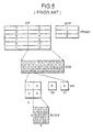
Fig. 5 is a view for explaining a hierarchical
structure of conventional image data.
Fig. 6 is a construction view of a conventional
coding portion.
Fig. 7 is a view for explaining conventional error
correction frame.
Fig. 8 is a construction view for explaining a
conventional motion-compensated interframe predictive
coding.
Fig. 9 is a construction view of a conventional
decoder.
Figs. 10A, 10B and 10C are a view for explaining a
principle of motion-compensated interframe predictive
coding method.
Fig. 11 is a view for explaining a correlation
between a transmitted and regenerated video data
according to a conventional image-information
regeneration control device.
Fig. 12 is a construction view for explaining an
image-information storage regenerating device
embodying the present invention.
Fig. 13 is a construction view of a multiplexed
data transmitting and receiving portion of a image
storage and communication system.
Figs. 14A, 14B and 14C are illustrative of video
data between modules of the receiver shown in Fig. 13.
according to the present invention.
Fig. 15 is illustrative of a stored paket format
according to the present invention.
Fig. 16 is a construction view of a transmitter of
multiplexed data transmitting and receiving portion
shown in Fig. 12.
Figs. 17A, 17B and 17C are illustrative of video
data between modules of the transmitter shown in Fig.
16.
Fig. 18 is another construction view of a
transmitter of multiplexed data transmitting and
receiving portion shown in Fig. 12.
Figs. 19A, 19B, and 19C are illustrative of video
data between modules of the transmitter shown in Fig.
18.
Fig. 20 is another construction view of a
transmitter of multiplexed data transmitting and
receiving portion shown in Fig. 12.
Figs. 21A, 21B, 21C and 21D are illustrative of
video data between modules of the transmitter shown in
Fig. 20.
Fig. 22 is construction view for
explaining an image-information storage regenerating
device.
Fig. 23 is a flow chart of image data for
explaining the operation of an image-information
storage regenerating device shown in Fig. 22.
Fig. 24 is a construction view for
explaining an image-information storage regeneration
device.
Fig. 25 shows an example of connection of an video
data regeneration control device of the present
invention with receiving terminals.
Figs. 26A and 26B are an explanatory views showing a
correlation between screen (frame) numbers of video
data stored.
Fig. 27 is an explanatory view 1 showing a
correlation between screen (frame) numbers of stored
video data and screen (frame) numbers of video data to
be transmitted by an image-information storage
regeneration device.
Fig. 28 is an explanatory view 2 showing a
correlation between screen (frame) numbers of video
data transmitted and screen (frame) number of video
data regenerated by an image-information storage
regeneration device.
Fig. 29 is a construction view of a center control
device shown in Fig. 25.
Fig. 30 is a view showing a state of data stored in
an video data storing portion of an image-information
storage regeneration device.
Fig. 31 is a view showing an example of transmitted
frames shown in Fig. 30.
Fig. 32 is a construction view of a multiplexed
data transmitting and receiving portion shown in Fig.
12.
Fig. 33 is illustrative of a stored packet format
according to the present invention.
PREFERRED EMBODIMENT OF THE INVENTION
Fig. 1 is a construction view of a conventional
multiplexed data transmitter and receiver device. In
Fig. 1, 1 is a storing data extracting portion, 2 is a
packet assembling portion, 3 is a packet disassembling
portion, 4 is a channel data generating portion, 5 is a
multiplexed data receiving portion and 6 is a
multiplexed data transmitting portion.
The storing data extracting portion 1 extracts
specified multiplexed data from the received channel
multiplexed data according to an instruction of a
system control portion. The packet assembling portion 2
assembles a packet from the received multiplexed data
according to an instruction of the system control
portion. The packet disassembling portion 3 extracts
reproducible multiplexed data from the packet outputted
by the storage device. The channel data generating
portion 4 generates channel multiplexed data from
multiplexed data outputted by the packet disassembling
portion according to an instruction of the system
control portion.
Figs. 2A and 2B show a conventional channel data
multiplexing format that is used for multiplexing data,
e.g., data for use in visual telephone service. This
format method is designated as an international
standard and, therefore, can assure the interconnectability
of, e.g., visual telephones. As shown in
Figs. 2A and 2B, the format includes areas 11 and 12
allocated respectively for audio data and video data, a
frame synchronization bits 13 and bits 14 for
interchange of capability-command between terminals.
An order of sending data into a communication circuit
is indicated with numeral 15. Data multiplexing
conditions can always be changed by using capability-command
communication bits 14.
Fig. 3 shows a conventional format of a packet to
be stored. A header 21 contains information on a
storing transmission rate, multiplexing rate and a data
encoding method. Numeral 22 denotes a quantity of sub-multiframes
comprised of packets, and numeral 23
indicates multiplexed data produced by using the format
shown in Fig. 2.
In storing, channel multiplexed data coming from a
network is received by the data extracting portion 1
that extracts therefrom multiplexed data to be stored
and transfers the extracted data to the packet
assembling portion 2. The packet assembling portion 2
assembles packets from the extracted multiplexed data
according to the packet format of Fig. 3. A header of
the format includes information on the transmitted data
multiplexing rate and their encoding method. The
packets are transferred as packet data to the storage
device.
In regeneration, the packet data from the storage
device is received by the packet disassembling portion
3 that informs the system control portion of the header
information of each packet. The system control portion
3 directs the channel data generating portion 4 to
match the operating mode of a terminal at storing side
with that of a terminal at regenerating side by using
BAS 14 shown in Fig. 2. After matching is realized by
the channel data generating portion, the packet
disassembling portion 3 disassembles the packets and
transfers the multiplexed data for regeneration to the
channel data generating portion 4 that in turn rewrites
FAS 13 and BAS 14 (Fig. 2) of the received multiplexed
data and sends the prepared channel multiplexed data
into the communication network.
Fig. 4 shows a configuration of a conventional
image-information storage control system which includes
terminals 31a-31e, a digital transmission network 32,
an video data storage control device 33, a receiving
portion 34, a communication control portion 35, a
transfer portion 36 and storage (recording) portion 37.
At present, the video data storage control device is
intended to be connected with audio-visual terminals
(hereinafter called as AV-terminal) based upon the
recommendation of ITU-T (International
Telecommunication Union Telecommunication
Standerdization Sector ). The video data coding will
conform to the system defined by the recommendation
H.261.
As shown in Fig. 4, the conventional image-information
storage control device is comprised of the
communication control portion 35, the receiving portion
34 and the transfer portion 36. When a storing start
instruction is given from the communication control
portion 35, coded video data received by the receiving
portion 34 are transferred through the transfer portion
36 to the storage device 37 (recording device like a
host machine). The transfer operation is ended with a
storing end instruction. The coded video data, as
mentioned above, are video data according to the
recommendation H.261. This coding method will be
described below:
Fig. 5 shows a hierarchical structure of coded
video data according to the recommendation H.261. The
hierarchy may be supposed as two-dimensionally divided
units for coding within a frame of video data, i.e., an
video frame (frame), a group of blocks (GOB), a macro
block (MB) and a block in descending order. Among them,
the video frame and the group of blocks include,
respectively, a self-synchronizing information in terms
of a unique word (PSC, GBSC) whereby a decoder can
recover synchronization at the beginning of
communication and in event of occurrence of
transmission error. Accordingly, each of these two
units may be considered as a transmissible structure
unit of coded data.
Fig. 6 is a construction view of a coder according
to the recommendation H.261, which includes an source
coding portion 41 and a transmission coding portion
42. The recommendation H.261 defines that a coder is
provided with a source coding portion 41 for producing
coded data with a reduced amount of information
contained in an video and a transmission coding
portion 42 that makes the coded data adapted to the
transmission line by giving them the resilience
against transmission error and inserting dummy
information for absorbing variation of an information
amount of coded data after coding. The transmission
coding portion 42 mainly performs forward error
correction (FEC) coding of source coded image data.
Fig. 7 shows a structure of an error correction
frame. The recommendation H.261 uses codes of (511,
493) BCH-code (Bose Chaundhuri Hocquenghem code).
Forward error correction coded data are made up of an
error correction frame (FEC frame) which is composed of
an error correction frame bit (1 bit) for synchronizing
a FEC frame according to a synchronization bit pattern,
a fill identifier (Fi) (1 bit), 492 bits of coded image
data or fill bits (data of all 1) and 18 bits of error
correction parity. The coded data thus prepared are
then transmitted.
Fig. 8 shows a structure of a motion compensative
inter-frame prediction coding system which includes a
differential arithmetic unit 51, an error coding
portion 52, an error decoding portion 53, an adder
portion 54, a frame memory portion 55 and a motion
compensative inter-frame predicting portion 56.
Coding algorithm according to the recommendation
H.261 is such that video data is coded by hybrid image
coding method which is a combination of motion
compensative inter-frame prediction and intra-frame
orthogonal transform coding. In the hybrid coding
system, an information content of video data is
reduced by using motion compensative inter-frame
prediction and video data can be alternatively encoded
in intra-mode (for coding within a frame only) that
means refreshing. This intra-mode is applied at
specified time intervals to prevent occurrence of a
mismatch between a sending side and a receiving side
due to calculation error or transmission error, and
that is also useful in case when the coding frame does
not have much correlation with a preceding one. The
hybrid coding system encodes a series of images mainly
by inter-frame motion compensative prediction.
Fig. 9 is a construction view of a decoder that
includes a transmission decoding portion 61 and a
source decoding portion 62. Decoding method according
to the recommendation H.261 has a flow chart reverse to
that of the fore-described coding methods according to
the same recommendation.
In video data storing, a transmitting AV-terminal
according to the recommendation H.261 encodes
successive objective frames by motion compensative
inter-frame prediction and sends the encoded video data
as shown in Fig. 10A. When an video data storing center
starts storing operation, coded image data by screens,
for example, Bo-Bn as shown in Fig. 10A are read-out
and stored in a storage such as a host machine. In
this case, the screen Bo is encoded by prediction with
reference to the frame B-1.
In image reproduction, as shown in Fig. 10B, the
coded video data, e.g., stored frames A-3 - A1 and Bo-Bn
are successively read from the host machine by the
video data storage center and sent to an AV-terminal.
These data maintain an integrity of coded video data
and they are, therefore, normally decoded at the AV-terminal.
While the screen Bo is, however, predicted with
reference to the screen B-1 at the time of data storing
(i.e., coding), it will be decoded with reference to
the screen A-1 that becomes a preceding object at the
time of video decoding. Namely, the screen Bo is
predicted according to different screens at coding and
decoding. As the result, the screen Bo can not
correctly be reproduced and displayed at the AV-terminal.
Furthermore, this may affect the subsequent
screens since screens B1 - Bn have been coded in
succession by inter-frame prediction. The screen images
may be damaged.
In the conventional image-information regeneration
control device, as described above, a screen number
(frame number) of video data (frame data) to be
transmitted and received by an audio-visual terminal is
the same as that of the corresponding video data stored
in a storage. Namely, the stored video data with its
unchanged screen (frame) number are transmitted to the
terminal. For example, as shown in Fig. 11, when video
data are stored in the order of screen (frame) numbers
"10, 12, 15, 17 ...", corresponding video data to be
transmitted are given the same frame numbers "10, 12,
15, 17 ...". Accordingly, when such video data are
regenerated in succession to a currently displayed
image or video data of different object, a discrepancy
of screen numbers may occur at a junction between two
different video sequences.
For instance, in case of continuously displaying
the stored video data in succession to a sequence of
screen images as shown in Fig. 11, jointed screen
(frame) numbers are described as "screen-image (1),
screen-image (3), screen-image (5), video data(10),
video data (12), video data(15) ..." which is
transmitted without any modification. This causes the
audio-visual terminal to regenerate the received video
data in the order of their screen (frame) numbers with
a discrepancy of screen (frame) numbers between
"screen-image (5)" and "video data (10)", i.e., an
farame interval corresponding to a split of image
sequences. In this case, video data behind the frame
interval is regenerated with a delay time.
Referring to drawings, a preferred embodiment of
the present invention will be described as follows:
Fig. 12 is a construction view for explaining an
example of an image-information storage regenerating
device according to the present invention. There are
shown a communication terminal 71, a communication host
72, a communication network 73 (e.g., ISDN), an image
input camera 74, an image output monitor 75, an audio
input-output handset 76, a terminal system control
portion 77, a video coding/decoding portion 78, an
audio coding/decoding portion 79, a multiplexed data
transmitting and receiving portion 80 of the
communication terminal 71 for multiplexing encoded
audio/video data and control information, and sending
multiplexed data to a channel, a host system control
portion 81, a multiplexed data transmitting and
receiving portion 82 of the host 72 for demultiplexing
control data from multiplexed data and multiplexing the
demultiplexed control data, and a storage device 93 for
storing data.
Moving-pictures taken by an image input camera 74
of a communication terminal 71 are encoded by inter-frame
prediction by the video coding/decoding portion
78 while audio signals inputted through the handset 76
are encoded by the audio coding/decoding portion 79.
The coded video data are multiplexed together with the
coded audio data and control information by the
multiplexed data transmitting and receiving portion 80
and transmitted over the communication network 73 to
the host 72. At the host side, the multiplexed data
sent from the communication terminal 71 are received by
the multiplexed data transmitting and receiving portion
82 whereby packet data to be stored is formed from the
received multiplexed audio/video data and transferred
to the storage device 83 wherein the packet data are
stored in the form of suitable files, i.e., the video
data are stored as arranged frame by frame or
continuous frames.
The stored data are read from the storage device 83
by the request of a user or the host and transferred
to the multiplexed data transmitting portion 82 of the
host 72, which, according to an instruction given by
the system control portion 81, rewrites the control
information of the data, that has been stored as
unchanged, and then transmits the data with the new
control information over the communication network to
the communication terminal 71. At the terminal side,
the multiplexed data with the rewritten control
information from the host side are received by the
multiplexed data receiver portion 80 that splits the
multiplexed data into the control information,
audio/video data and sends the control information to
the system control portion 77.
The coded video data received and demultiplexed by
the multiplexed data transmitting and receiving portion
80 are transferred to the video coding/decoding portion
78 that decodes the video data according to an
instruction of the system control portion 77 and
displays moving-pictures on a display screen of the
monitor 75. The demultiplexed audio data are decoded
and regenerated by the audio coding/decoding portion 79
and outputted through the handset 76. Since
communication over the channel is always conducted in
two-ways during both 'store' and 'regenerate'
operations, the control information can be transmitted
to and from the terminal irrespective of existence or
absence of the video data while the channel is kept
ON therebetween.
Fig. 13 is a construction view of a multiplexed
data transmitter and receiver device. In Fig. 13, 89 is
a receiving portion of the multiplexed data transmitter
and receiver device, 90 is a transmitting portion of
the multiplexed data transmitter and receiver device,
91 is a channel data demultiplexing portion, 92 is an
error correcting portion according to forward error
correction (FEC) control system, 93 is a video frame
extracting portion, 94 is a packet assembling portion,
95 is a packet disassembling portion, 96 is a data
processing portion and 97 is a channel data
multiplexing portion.
The channel data demultiplexing portion 91 separates
received channel multiplexed data into different
components such as audio/video data and other
information according to an instruction of a system
control portion (not shown). The error correcting
portion 92 performs error correcting operation on video
data outputted from the channel data demultiplexing
portion 91. The video frame extracting portion 93
extracts a video frame from the error corrected data.
The packet assembling portion 94 produces a packet by
collecting the video frame from the video frame
extracting portion 93 and audio data from the channel
data demultiplexing portion 91. The packet
disassembling portion 95 demultiplexes a packet read
from a storage device into audio/video data. The data
processing portion 96 performs some due processing
operation on the data outputted from the packet
disassembling portion 95 and the channel data
multiplexing portion 97 produces channel multiplexed
data from the data outputted from the data processing
portion 96.
Figs. 14A to 14C are illustrative of video data A,
B and C between modules of the receiver portion shown
in Fig. 13. Fig. 14A corresponds to a signal "A" shown
in Fig. 13, which is comprised of a synchronizing
signal for FEC, parity bits, fill bits for adjusting
an amount of coded data and an information bit. Fig.
14B corresponds to a signal "B" shown in Fig. 13, which
is corrected for error and relieved of redundant data,
e.g., fill bits. Fig. 14C corresponds to a signal "C"
shown in Fig. 13, which is a video frame extracted by
PSC (picture start code).
Fig. 15 shows a structure of a packet to be stored,
which includes information: a header containing
information 111 on multiplexing rate at storing,
encoding method and encoding capability; a video data
length 112, a audio data length 113; the number of
video frames 114 in a paket; a data length of a video
frame and video frame data 115; and audio data 116.
The operation of the image-information storage
regenerating device according to the present invention
is as follows:
At data storing, the channel data demultiplexing
portion 91 splits the multiplexed data received through
the network into audio/video data and other components
and, then, transfers the video data to the error
correcting portion 92 and audio data to the packet
assembling portion 94. The error correcting portion 92
receives video data as a signal in the state shown in
Fig. 14A, conducts error correction of the data and
outputs video data as a signal in the state shown in
Fig. 14B to the video frame extracting portion 93 that
in turn searches PSC (picture start code) in the
received data and outputs data in the state shown in
Fig. 14C to the packet assembling portion 94. The
packet assembling portion 94 assembles a packet of
received audio/video data according to the packet
format shown in Fig. 15, then it writes the header
information on multiplexing rate, encoding method and
coding capability necessary for regeneration of the
data and outputs the prepared data to the storage
device 83.
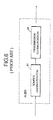
Fig. 16 is a construction view of a transmitter of
the multiplexed data transmitting and receiving means
shown in Fig. 12. There are shown a packet
disassembling portion 121, a fill bit inserting
portion 122, a FEC frame generating portion 123 and a
channel data multiplexing portion 124. The packet
disassembling portion 121 disassembles a received
packet into audio/video data and other data. The fill
bit inserting portion 122 inserts fill bits into the
video data outputted from the packet disassembling
portion 121. The FEC frame generating portion 123
produces a FEC frame from the video data outputted from
the fill bit inserting portion 122. The channel data
multiplexing portion 124 generates a channel
multiplexed data from the video data outputted from the
FEC frame generating portion 123 and the audio data
outputted from the packet disassembling portion 121.
Figs. 17A to 17C are illustrative of video data
between modules of the transmitter portion shown in
Fig. 16. Fig. 17A corresponds to a signal "D" shown in
Fig. 16, which is a video frame data. Fig. 17B
corresponds to a signal "E" shown in Fig. 16, which is
filled with fill bits. Fig. 17C corresponds to a signal
"F" shown in Fig. 16, which is a FEC frame containing
a synchronizing signal for FEC and parity bits for
correction of transmission error.
The operation of the transmitter portion shown in
Fig. 16 is as follows.
At data regenerating, the packet disassembling
portion 121 receives a packet outputted from the
storage device 83, extracts therefrom header
information and transfers it to the system control
portion 81 that in turn instructs the channel data
multiplexing portion 124 to match with each other the
operating modes of a regenerating side terminal and a
sending side terminal by using BAS 14 shown in Fig. 2.
After matching for operation mode of the terminal is
completed at the channel data multiplexing portion 124,
the packet disassembling portion 121 disassembles a
packet and transfers video data to the fill bit
inserting portion 122 and audio data and other
information to the channel data multiplexing portion
124.
The fill bit inserting portion 122 inserts fill
bits into the video data to enable the communication
terminal to establish and maintain synchronization of
FEC frame before regenerating the stored video data
thereat, then it transfers the video data to the FEC
frame generating portion 123 that in turn produces a
FEC frame and transfers it to the channel data
multiplexing portion 124. The channel data multiplexing
portion 124 multiplexes video data together with
audio data according to a multiplexing format showing
in Fig. 2 and sends the multiplexed data into the
network.
The present invention provides a data storing
format adapted to effectively overcome problems, which
may arise at data regeneration in a video storage and
delivery system, and realizes quick and smooth
regeneration of stored video data. Namely, the channel
data demultiplexing portion 91 takes the multiplexed
input data to respective components. The error
correcting portion 92 corrects an error of video data
outputted from the channel data demultiplexing portion
91. The video frame extracting portion 93 extracts a
video frame from the data outputted from the error
correcting portion 92. The packet assembling portion 94
assembles a packet of the video data outputted from the
video frame extracting portion 93 and the audio data
outputted from the channel data demultiplexing portion
91. The storage device 83 stores therein the packet
outputted from the packet assembling portion 94.
Accordingly, video data are stored as video frames in
the storage device 83.
A packet comprised of video data and audio data
with header information is outputted from the storage
device 83 to the packet disassembling portion 121 that
disassembles said packet. The fill bit inserting
portion 122 inserts fill bits in video data outputted
from the packer disassembling portion 121. The FEC
frame generating portion 123 generates a FEC frame from
the video data outputted from the fill bit inserting
portion 122. The channel data multiplexing portion 124
produces multiplexed data of video data outputted from
the FEC frame generating portion 123 and of audio data
and other information outputted from the packet
disassembling portion 121. Thus multiplexed data are
effective to control synchronization at the terminal
for regeneration of delivered images.
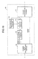
Fig. 18 shows another construction of a transmitter
of the multiplexed data transmitting and receiving
portion shown in Fig. 12. There are indicated a
transmitter portion 106, a packet disassembling 131, a
fill bit inserting portion 132, a FEC frame generating
portion 133, a channel data multiplexing portion 134
and a data amount supervising portion 135.
The packet disassembling portion 131 disassembles
a received packet into audio/video data. The fill bit
inserting portion 132 inserts fill bits into the
received video data. The FEC frame generating portion
133 produces a FEC frame of the received video data.
The channel data multiplexing portion 134 generates
channel multiplexed data. The data amount supervising
portion 135 monitors an amount of information and
controls insertion of fill bits as need be.
Figs. 19A to 19C are illustrative of video data
between modules of the receiver portion shown in Fig.
18. Fig. 19A corresponds to a signal "G" shown in Fig.
18, which is video frame data. Fig. 19B corresponds
to a signal "H" shown in Fig. 18, which is data filled
with fill bits. Fig. 19C corresponds to a signal "I"
shown in Fig. 18, which is a FEC frame containing a
synchronizing signal for FEC and parity bits for
transmission error correction.
The operation of the transmitter portion shown in
Fig. 18 is as follows.
At data regenerating, the packet disassembling
portion 131 receives a packet outputted from the
storage device 83, extracts therefrom header
information and transfers it to the system control
portion 81 that in turn directs the channel data
multiplexing portion 89 to make the operating mode of
receiving side terminal with that of sending side
terminal by using BAS 14 shown in Fig. 2. After
matching is completed at the channel data multiplexing
portion 134, the packet disassembling portion 131
disassembles a packet, transfers video data to the fill
bit inserting portion 132 and the data amount
supervising portion 135 and transfers audio data and
other information to the channel data multiplexing
portion 134.
The fill bit inserting portion 132 inserts fill
bits into the video data under control of the data
amount supervising portion 135 and transfers the video
data to the FEC frame generating portion 133 that in
turn produces a FEC frame and transfers it to the
channel data multiplexing portion 134. The channel data
multiplexing portion 134 multiplexes audio/video data
according to a multiplexing format shown in Fig. 2 and
enters the multiplexed data into the network.
The present invention is thus directed to prevent
any terminal from being subjected to overflow and
underflow of its buffer memory when regenerating video
data in a video storage and delivery system.
A packet conprised of audio/video data with header
information is outputted from the storage device 83 to
the packet disassembling portion 131 that disassembles
said packet. The fill bit inserting portion 132 inserts
fill bits into video data outputted from the packet
disassembling portion 131. The data amount
supervising portion 135 monitors an amount of the video
data outputted from the packet disassembling portion
131 and controls the fill bit inserting portion 132.
The FEC frame generating portion 133 generates a FEC
frame from the video data outputted from the fill bit
inserting portion 132. The channel data multiplexing
portion 134 produces multiplexed data of the video data
outputted from the FEC frame generating portion 133
together with the audio data and other information
outputted from the packet disassembling portion 131.
The information amount of the stored image is thus
controlled for regeneration at a terminal.
Fig. 20 shows another construction of a transmitter
of the multiplexed data transmitting and receiving
portion shown in Fig. 12. In Fig. 20, numeral 136
designates a transmission rate matching portion and
other potions similar in function to those of Fig. 18
are given the same reference numerals.
The tranission rate matching portion 136 regulates
an output of the received video data to match with due
transmission rate. For instance, video data which were
stored at a rate of 10 video frames for a second, 10
video frames are outputted for a second, irrespective
of a data transmission rate at data regeneration.
Figs. 21A to 21D are illustrative of video data
between modules of the receiver portion shown in Fig.
20. Fig. 21A corresponds to a signal "J" shown in Fig.
20, which is video frame data. Fig. 21B corresponds to
a signal "K" shown in Fig. 20, which is video frame
data with a controlled output. Fig. 21C corresponds
to a signal "M" shown in Fig. 20, which is filled with
fill bits. Fig. 21D corresponds to a signal "N" shown
in Fig. 20, which is a FEC frame containing a
synchronizing signal for FEC and parity bits for
transmission error correction.
The operation of the transmitter portion shown in
Fig. 20 is as follows.
At data regenerating, the packet disassembling
portion 131 receives a packet outputted from the
storage device 83, extracts therefrom header
information and transfers it to the system control
portion 81 that in turn directs the channel data
multiplexing portion 134 to match the operating mode of
the receiving side with that of the sending side by
using BAS 14 shown in Fig. 2. If the channel data
multiplexing portion 134 can not realize operation mode
matched with the receiving terminal because the
receiving terminal for regeneration has faster channel
rate than a terminal that transmitted the stored data,
it changes the transmission rate with the receiving
terminal in an operation mode being closest to that of
the terminal side. After completion of changeing the
transimisson rate with the receiving terminal, the
packet disassembling portion 131 disassembles a packet
and transfers video data to the transmission rate
matching portion 136 that in turn adjusts an output of
the received video data and transfers the video data
with the controlled output to the fill bit inserting
portion 132 and the data amount supervising portion
135.
The fill bit inserting portion 132 inserts fill
bits into the video data under control of the data
amount supervising portion 135 and transfers the video
data to the FEC frame generating portion 133 that in
turn produces a FEC frame and transfers it to the
channel data multiplexing portion 134. The channel data
multiplexing portion 134 multiplexes audio/video data
according to a multiplexing format showing in Fig. 2
and transmits the multiplexed data over the network to
the terminal.
As described above, the present invention enables a
video storing and delivery system to regenerate stored
video data at a terminal even if the latter has a
different transmission rate from the transmission rate
of the video data at storing. Namely, the packet
disassembling portion 131 disassembles a packet
comprised of audio/video data with header information.
The transmission rate matching portion 136 performs
matching a transmission rate of the video data
outputted from the packet disassembling portion 131.
The data amount supervising portion 135 monitors an
amount of the video data and the fill bit inserting
portion 132 inserts fill bits into the video data. The
FEC frame generating portion 133 generates a FEC frame
from the video data outputted from the fill bit
inserting portion 132. The channel data multiplexing
portion 134 produces multiplexed data of the video data
outputted from the FEC frame generating portion 133
together with the audio data and other information
outputted from the packet disassembling portion 131.
The above-mentioned processing makes it possible to
regenerate the stored video data at a terminal having a
transmission rate different from that of the data
storing side.
Fig. 22 is a construction view for
explaining an example of image-information storage
regenerating device,
which includes a receiving portion 141, a communication
control portion 142, a transfer portion 143, a decoding
portion (H.261) 144 and an intra-frame coding portion
(H.261) 145.
First, the receiving portion 141 receives coded
video data and sends said data to the decoding portion
(H.261) 144 or the transfer portion 143 under the
control of the communication control portion 142. The
coded video data are conventionally coded video data
which are, similarly as usual video data, are encoded
by hybrid coding method combining motion compensative
inter-frame prediction with intra-frame orthogonal
transform coding.
The communication control portion 142 switches over
control channel of transfer portion 143 and an video
data transmission line in the state of beginning or
ending of data storing. The decoding portion (H.261)
144 decodes the coded video data to reproduce the video
data. This portion, like a usual decoder H.261,
executes processing such as motion compensative
prediction decoding and inverse discrete cosine
transform (inverse DCT).
In the intra-frame coding portion (H.261) 145, the
video data decoded by the decoding portion (H.261) 144
are encoded again but in the intra-mode only. The
transfer portion 143 receives the coded video data from
the intra-frame coding portion (H.261) 145 or the
receiving portion 141 and transfers said data to the
host center (storage) under the control of the
communication control portion 142.
Fig. 23 is a flow chart for explaining the
operation of the image-information storage regenerating
device shown in Fig.
22. The operation of this device is as follows:
During a data storing cycle from the storing end to
the storing start (with an initial screen - the first
unit of a moving video sequence), coded video data are
first received (step 1), check is made whether storing
being executed or not (step 2), and, if not, the
received coded data are decoded (step 3). Next, check
is made whether the data relates to an initial screen
with which storing starts (step 4), and, if not, the
operation returns to step 1. If the data is an initial
screen, said initial screen is read out from a frame
memory of the decoding portion (H.261) 144 (step 3) and
is sent through the intra-frame coding portion (H.261)
145 to the transfer portion 143 (step 5). Upon receipt
of a "transfer" command from the communication control
portion 142 the transfer portion 143 starts
transferring the video data. It stops the operation
when the storing is finished (step 6).
The intra-frame coding portion (H.261) 145 encodes
an initial screen of moving video sequence in the
intra-mode specified in the recommendation H.261 and
outputs it as coded video data. For this purpose, the
intra-frame coding portion (H.261) 145 does not needs
to execute inter-frame predictive coding of video data,
thereby it becomes unnecessary to perform motion
compensative prediction, which takes a grater part of
processing load for a usual H.261 coder, and to use a
frame memory for that purpose. Consequently, the intra-frame
coding portion 145 is required to perform very
simple processing and have a simple hardware like a
still image coder.
When the device being in the state of storing video
data, i.e., step 2 judges the video data are now
stored, coded video data, which are subsequent to an
initial screen comprising of video data coded in the
intra-mode only, are sent screen by screen directly
from the receiving portion 141 to the transfer portion
143, bypassing the coding portion (H.261) 144 and the
intra-frame coding portion (H.261) 145. They are
further sent to the storage and stored therein.
As described above, according to the present
invention, an initial screen of coded video data to be
stored is a frame of video data coded by intra-frame
coding, which serves as a reference frame to which
subsequent frame relates, and further frames are of
video data coded by hybrid coding method using a
combination of conventional motion compensative inter-frame
predictive coding and intra-frame orthogonal
transfer coding. Therefore, it becomes possible to make
up a sequence of video data, which has a frame coded by
intra-frame coding at the head and includes subsequent
frames coded by conventional hybrid coding method.
Fig. 24 is an another construction view for
explaining an example of image-information storage
regeneration device,
which includes an video data reading portion 151, a
screen-image reading portion 152, a screen number
rewriting control portion 153, a transmission frame
processing portion 154 and a channel control portion
155.
First, the video data reading portion 151 reads
video data, which are encoded according to an encoding
system based upon the ITU-T recommendation H.261 , from
a storage device. The screen-image reading portion 152
reads conversational screen-images, i.e., pages
(screenfuls) of information such as to indicate a
service menu or a guidance to use the service. The
screen number rewriting control portion 153 gives an
instruction to rewrite screen (frame) numbers of the
coded information stored in the storage device and
read-out therefrom for further transmission to an AV-terminal.
The transmission frame processing portion 154
rewrites screen (frame) numbers of the coded video data
read by both the video data reading portion 151 and the
screen-image reading portion 152 according to the
instruction given by the screen (frame) number
rewriting control portion 153 to prepare frame
information for transmisson, which are transmitted by
the channel control portion 155 over a communication
channel to the AV-terminal.
Fig. 25 is a view for explaining an exemplified
system in which a video data regeneration control
device embodying the present invention is used in
combination with receiving terminals. The system
includes a storage device 161, an video data control
device 162, a communication channel 163, AV-terminals
164-1 - 164-n and a center control device 165.
The storage device 161 stores records of coded
video data. The video data regeneration control device
162 is an embodiment of the present invention, which
reads video data and screen-images from the storage
device 161 and transmits them to the AV-terminal 164-1.
The center control device 165 is comprised of the
storage device 161 and the video data regeneration
control device 162. The communication channel 163 may
be a public network or a private channel. The AV-terminals
164-1 - 164-n are adapted to communicate with
the video data regeneration control device 162 over the
communication channel 163 and receives coded video data
from the storage device 161 and regenerates the data in
the form of video images on its display screen.
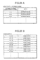
Figs. 26A and 26B show a correlation between frames
and screen numbers (frame numbers) of video data
encoded according to the encoding method defined by the
ITU-T recommendation H. 261 and stored in the storage
device 161. Fig. 26A shows a sequence of video data(1)
and Fig. 26B shows a sequence of video data(2). The
frames are given respective serial screen (frame)
numbers.
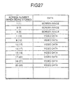
Fig. 27 is a view showing a correlation between
screen (frame) numbers of video data to be transmitted
and screen (frame) numbers of stored video data when
transmitting coded video data of different objects from
a storage to an AV-terminal. An example of
communication between the video data regeneration
control device and an AV-terminal is described as
follows:
Upon receipt of a communication-start request from
an AV-terminal, the video data regeneration control
device 162 reads coded video data stored in the storage
device 161 and transmits the data to the AV-terminal
164-1. In this case, a sequence of the video data 1
read-out in the order of frame numbers from the storage
device 161 as shown in Figs. 26A and 26B are not
subjected to any processing by the transmission frame
processing portion 154 and transmitted through the
communication channel control portion 155 to the AV-terminal
164-1 that in turn regenerates a sequence of
the received video data in the order of their frame
numbers.
If two different video data sequences are
successively read from the storage device 161 and
transmitted without any processing to the AV-terminal
164-1, two image sequences are reproduced at the same
order of frame numbers (i.e. frame interval) as those
of the data stored in the storage device 161, that
causes a delay between the last frame of the preceding
image sequance and the top frame of the succeeding
image sequance as shown in Fig. 11, giving an
impression of discontinuity of the reproduced images.
To avoid this, in the video data regeneration control
device 162, the screen number rewriting control portion
153 instructs the transmission frame processing
portion 154 to rewrite screen (frame) numbers of the
succeeding video data as shown in Fig. 27.
For instance, the first transmittable video data 1
(screen images) shown in Fig. 26A without rewriting its
frame numbers is first transmitted through the channel
control 155 to the AV-terminal 164-1. Next, the video
data reading portion 151 reads video data 2 shown in
Fig. 26B from the storage device 161 and the the screen
(frame) number rewriting control portion 153 instructs
the transmission frame processing portion 154 to
change a screen (frame) number "10" into "7" of the top
frame which is then transmitted through the channel
control portion 155 to the AV-terminal 164-1.
Succeeding frames of the same video data are subjected
to rewriting their numbers "12" into "9", "15" into
"12" and so on as shown in Fig. 27, keeping the same
(unchanged) increment in numbers (i.e., at a specified
constant frame interval), and, then, they are
transmitted one by one to the AV-terminal 164-1. Frames
of another different video data are successively
processed by similarly rewriting their number and
transmitted to the AV-terminal. As shown in Fig. 28,
this processing realizes smooth and continuous
regeneration of concatenated video data without causing
a delay at a junction of two different video data.
As described above, the present invention is
directed to the provision of an image-information
regeneration control device including a frame number
rewriting control portion, which, in case of
transmitting two or more different groups of coded
video data from a storage device to an AV-terminal,
rewrites a top screen (frame) number of succeeding
different video data into a number consistent with that
of the last frame of preceding different video data and
rewrites successive frames of the same video data into
respective numbers having a constant (not changed)
increment for the purpose of realizing smooth and
continuous reproduction of different video data,
independent of their stored frame numbers, at any AV-terminal.
Namely, the video data regeneration control device
for reading any coded video data from the storage
device for further transmission is connected through a
communication channel with the AV-terminal for
receiving and decoding the video data for reproduction
of images. The video data regeneration control device
includes a frame number rewriting control portion
which, in case of transmitting a plurality of different
groups of coded video data from a storage device to an
AV-terminal, instructs a transmission frame processing
portion to rewrite frame numbers of a group of video
data in succession to a preceding group in such a way
that a top frame of the subsequent group of video data
may have a number consistent with that of the last
frame of the precedent group and the subsequent frames
of the same group may have respective new serial
numbers keeping a specified (unchanged) increment.
Thus processed video data are then transmitted to the
AV-terminal that can successively decode the received
video data without delay between the end of the
preceding video data group and the start of the
subsequent group.
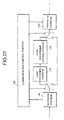
Fig. 29 shows a configuration of the center control
device shown in Fig. 25, which comprises an video data
storage portion 171, a terminal-capability control
portion 172, a frame (screen) number rewriting control
portion 173, a transmission frame processing portion
174 and a channel control portion 175. Other portions
similar in function with those of Fig. 25 are denoted
by the same reference codes.
The video data storage portion 171 stores records
of video data encoded according to the coding method
defined by the ITU-T recomendation H.261. The
terminal-capability control portion 172 controls
decoding capability of each terminal that receives
coded video data and reproduces the images on its
display screen. The frame number rewriting control
portion 173 gives an instruction to rewrite frame
numbers of the coded video data stored in the storage
portion 171 before they are transmitted to a terminal.
The transmission frame processing portion 174 reads the
video data from the storage portion 171, rewrites the
video frame numbers according to the instruction given
by the frame number rewriting control portion and
prepare frames for transmission. The channel control
portion 175 transmits the prepared frames to the
receiving terminal over the communication channel 163.
Fig. 30 shows a correlation between screen (frame)
numbers and frames of the video data that is encoded at
an frame interval 1/29.97 seconds (hereinafter
described as 1/30 sec.) according to a coding method
defined by the ITU-T recomendation H.261 and stored in
the video data storage portion 171 shown in Fig. 29.
The frames are given respective consecutive numbers.
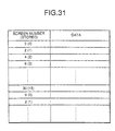
Fig. 31 shows correlation between the frame numbers
of the coded video data stored in the storage portion
(Fig. 30) and frame numbers of the frames to be
transmitted to the terminal that can decode video data
at a minimum frame interval of 2/29.97 seconds
(hereinafter described as 2/30 sec.).
An example of communication between the center
control device 165 and the terminal 164-1 is described
as follows:
When the center control device 165 receives a
communication-start request from the terminal 164-1, it
operates the terminal-capability control portion 172 to
check the decoding capability of the terminal before
transmitting thereto the coded video data stored in the
video data storage portion 171. When an frame interval
of the stored frames is of 1/30 sec. and the terminal
has sufficient capability to decode coded video data
frames at minimum frame interval of 1/30 sec, the
transmission frame processing portion 174 reads the
coded video data from the storage portion 171 in the
order of frame numbers as shown in Fig. 31 and
transfers them, without any kind of processing, to the
channel control portion 175 that successively transmits
the received frames to the terminal 164-1 over the
communication channel. The terminal 164-1 decodes the
received coded video data at a frame interval of 1/30
sec.
On the other hand, when the terminal 164-1 has a
capability to decode frames at a minimum frame
interval of 2/30 sec., i. e. it can not decode the
coded video data stored in the storage portion 171, the
center control device 165 causes the frame-number
rewriting control portion 173 to give the transmission
frame processing portion 172 an instruction necessary
for rewriting frame numbers as shown in Fig. 31. In
this case, a first transmissive frame is a frame (1) of
the stored coded video data shown in Fig. 30, which is
not subjected to rewriting its number and transmitted
through the channel control portion 175 to the terminal
164-1.
Next, the frame number rewriting control portion
173 requests the transmission frame processing portion
174 to reads a frame (2) shown in Fig. 30 from the
video data storage portion 171 and changes the frame
number of the frame (2) from "1" into "2". The frame is
then transmitted through the channel control portion
175 to the terminal 164-1. A frame (3) is next read
from the video data storage portion 171, subjected to
changing its number from "2" into "4" and transmitted
to the terminal. The subsequent frames are successively
renewed in their numbers and transmitted to the
terminal.
In the above-described example, it is supposed that
the terminal has a capability to decode the frames at
an frame interval of 2/30 sec. corresponding to that
the half number of the frames of video data stored in
the storage portion 171 can be decoded within a same
time scale. If the terminal has a capability to decode
frames at a frame interval of 3/30 seconds (standard
value is 3/29.97), the first transmissive frame (1) is
read and transmitted without any processing. The frames
(2) and (3) to be transmitted second and third are
subjected to rewriting their numbers to "3" and "6"
respectively. Subsequent frames are similarly processed
with renewed numbers before transmission to the
terminal.
Similarly, when terminal can decode frames at a
minimum frame interval of 4/30 seconds (standard value
is 4.29.97), the initial frame (1) is read and
immediately transmitted to the terminal. The second and
third transmissive frame (2) and (3) are subjected to
rewriting their numbers to "4" and "8" respectively.
As described above, the center control device 165
according to the present invention is provided with a
frame number rewriting control portion 173 for
rewriting frame numbers of coded video data stored in a
storage portion 171, which, thereby, is capable of
rewriting the screen (frame) numbers of the coded video
data in accordance with the decoding capability of the
receiving terminal before transmitting the video data
thereto.
The center control device 165 wherein coded video
data is stored and a terminal for decoding coded video
data to reproduce therefrom video are connected with
each other through a communication channel there
between. The center control device 165 includes a
terminal-capability control portion 172 for controlling
decoding capability of the terminal and a frame
number rewriting control portion 173 for instructing a
transmission frame processing portion 174 for rewriting
frame numbers according to the decoding capablity of
the terminal, which, therefore, is capable of preparing
frames having renewed numbers and being slowly
reproducible at the terminal, thus realizing a
communication between the center control device 165 and
the terminal.
Fig. 32 is a construction view for explaining an
example of a multiplexed data transmitting and
receiving portion of the host shown in Fig. 12. In Fig.
32, there are shown a receiver portion 89, a
transmitter portion 105, a channel data demultiplexing
portion 91, an error correcting portion 92 for FEC
(forward error correction), a video frame extracting
portion 93 and a packet assembling portion 94, a time
stamp generating portion 100, a packet disassembling
portion 101, a data processing portion 102, a
differential delay absorbing portion 103 and a channel
data multiplexing portion 104.
The channel data demultiplexing portion 91
separates multiplexed data received through the
network into respective components. The error
correcting portion 92 corrects transmission error of
demultiplexed video data, and the video frame
extracting portion 93 extracts a video frame from the
error corrected video data. The packet assembling
portion 94 assembles a packet of the audio/video data.
The time stamp generating portion 100 generates a time
stamp by using an octet timing signal outputted from
the channel data separating portion 91. The packet
disassembling portion 101 demultiplexes a received
packet into audio/video data and other information. The
data processing portion 102 make some due processing of
audio/video data. The differential delay absorbing
portion 103 absorbs a possible differential delay of
the processed audio/video signals in their regeneration
by using attached thereto time stamps. The channel data
multiplexing portion 104 generates channel multiplexed
data of audio/video data and other information received
from the differential delay absorbing portion 103.
Figs. 14A to 14C are illustrative of video data A,
B and C between modules of the receiver portion shown
in Fig. 32. Fig. 14A corresponds to a signal "a" shown
in Fig. 32, which is comprised of a synchronizing
signal for FEC, parity bits, fill bits for adjusting
an amount of coded data, and an information bit. Fig.
14B corresponds to a signal "b" shown in Fig. 32, which
is corrected for error and relieved of redundant data,
e.g., fill bits. Fig. 14C corresponds to a signal "c"
shown in Fig. 32, which is a video frame extracted by
PSC (picture start code).
Fig. 33 shows a structure of a packet to be stored,
which includes information: a header containing storing
information on multiplexing rate, encoding method and
encoding capacity 181; a video data length 182, an
audio data length 183; the number of stored video
frames 184; a time stamp of video data, data length of
a video frame and video frame data 185; and a time
stamp of audio data 186 and audio data 187.
The operation of the multiplexed data storing and
regenerating device according to the present invention
is as follows:
At data storing, the channel data demultiplexing
portion 91 splits multiplexed data received through the
network into audio/video data and other information
and, then, transfers the video data to the error
correcting portion 92, the audio data to the packet
assembling portion 94 and octet timing information to
the time stamp generating portion 100. The time stamp
generating portion 100 generates a time stamp per octet
and outputs it to both the video frame extracting
portion 93 and the packet assembling portion 94. The
error correcting portion 92 receives video data as a
signal in the state shown in Fig. 14A, conducts error
correction of the data and outputs video data as a
signal in the state shown in Fig. 14B to the video
frame extracting portion 93.
The video frame extracting portion 93 searches PSC
(picture start code) in the received data and outputs
data in the state shown in Fig. 14C and a time stamp
corresponding to the time point of finding the PSC to
the packet assembling portion 94. The packet assembling
portion 94 assembles a packet from the received
audio/video data and attached time stamps according to
the packet format shown in Fig. 33, then it writes the
header information on multiplexing rate, encoding
method and coding capacity necessary for regeneration
of the data and outputs the prepared data to the
storage device 83.
At data regenerating, the packet disassembling
portion 101 receives a packet outputted from the
storage device 83, extracts therefrom header
information and transfers it to the system control
portion 81 that in turn instructs the channel data
multiplexing portion 104 to make the operating mode at
receiving side match with that of sending side by
using BAS 14 shown in Fig. 2.
After completion of matching at the channel data
multiplexing portion 104, the packet disassembling
portion 101 disassembles a packet and transfers
audio/video data and attached time stamps to the data
processing portion 102 that in turn performs some due
operations on the audio/video data and outputs the
processed audio/video data with the time stamps to the
differential delay absorbing portion 103. The
differential delay absorbing portion 103 absorbs a
differential delay of the respective component data by
the attached time stamp and outputs the prepared data
to the channel data multiplexing portion 104 that in
turn multiplexes the audio/video data and other
information according to the multiplexing format shown
in Fig. 2 and sends the multiplexed data into the
network.
According to an aspect of the present invention, an
image-information storage regenerating device which can
collect and store multiplexed data of audio/video and
other information from video data communication
terminals, and regenerate the stored data through their
terminal, is characterized in that multiplexed data
transmitting and receiving means 82 receive multiplexed
data from a terminal 71 for multiplexing an input
signal, said signal being anyone or any combination of
video, audio, and other kind of data, for the purpose
of storing said data at host side, and transmit stored
data as regenerated data, and storage means 83 store
therein multiplexed data containing video, audio, and
other kind of data, said data being received by the
multiplexed data transmitting and receiving means 82,
and output therefrom the stored data for regeneration,
whereby the multiplexed data transmitting and receiving
means 82 separates multiplexed data and the storage
means 83 stores therein video data by a separate video
frame or continuous video frames. The multiplexed data
transmitting and receiving means 82 is provided with
channel data demultiplexing means to separate
respective component data from an input signal of
multiplexed data, said data being anyone or any
combination of video, audio, and other kind of data,
error correcting means 92 to correct an error of video
data outputted from the channel data demultiplexing
means 91, video frame extracting means 93 to extract a
video frame from video data outputted from the error
correcting means 92, and packet assembling means 94 to
assemble a packet from video data and audio data, said
video data outputted from the video frame extracting
means 93 and said audio data outputted from the channel
data separating means 91, and the storage means 83
stores therein an assembled packet outputted from the
packet assembling means 94 by arranging video data
therein by a separate video frame or continuous video
frames. Further, the multiplexed data transmitting and
receiving means 82 is provided with packet
disassembling means 121 to disassemble a packet
outputted from the storage means 83 into respective
components, fill bit inserting means 122 to optionally
insert fill bits into video data outputted from the
packet disassembling means 121, error correction frame
generating means 123 to produce an error correction
frame of video data outputted from the fill bit
inserting means 122, and channel data multiplexing
means 124 to multiplex video data multiplexing means
124 to multiplex video data outputted from the error
correction frame generating means 123 together with
data outputted from the packet disassembling means 121,
and the multiplexed data transmitting and receiving
means 82 can maintain synchronization of error
correction frame of the communication terminal for
regenerating stored video data. The multiplexed data
transmitting and receiving means 82 is provided with
packet disassembling means 131 to disassemble a packet
outputted from the storage means 83 into respective
components, fill bit inserting means 132 to insert fill
bits into video data outputted from the packet
disassembling means 131, data amount supervising means
135 to supervise an information content of video data
outputted from the packet disassembling means 131 and
to control the fill bit inserting means 132, error
correction frame generating means 133 to produce an
error correction frame of video data outputted from the
fill bit inserting means 132, and channel data
multiplexing means 134 to multiplex video data
outputted from the error correction frame generating
means 133 together with data outputted from the packet
disassembling means 131, and the multiplexed data
transmitting and receiving means 82 can maintain
synchronization of error correction frame of the
communication terminal for regenerating stored video
data. The multiplexed data transmitting and receiving
means 82 is provided with packet disassembling means
131 to disassemble a packet outputted from the storage
means 83 into respective components, transmission speed
matching means 136 to match transmission rate with
video data outputted from the packet disassembling
means 131, fill bit inserting means 132 to insert fill
bits into video data outputted from the packet
disassembling means 131, data amount supervising means
135 to supervise an information content of video data
outputted from the packet disassembling means 131 and
to control the fill bit inserting means 132, error
correction frame generating means 133 to produce an
error correction frame of video data outputted from the
fill bit inserting means 132, and channel data
multiplexing means 134 to multiplex video data
outputted from the error correction frame generating
means 133 together with data outputted from the packet
disassembling means 131, and the multiplexed data
transmitting and receiving means 82 can maintain
synchronization of error correction frame of the
communication terminal for regenerating stored video
data.