EP1024642B1 - Verfahren und Vorrichtung zur dynamischen Steuerung der Bereitstellung von differenzierter Diensten - Google Patents
Verfahren und Vorrichtung zur dynamischen Steuerung der Bereitstellung von differenzierter Diensten Download PDFInfo
- Publication number
- EP1024642B1 EP1024642B1 EP99310504A EP99310504A EP1024642B1 EP 1024642 B1 EP1024642 B1 EP 1024642B1 EP 99310504 A EP99310504 A EP 99310504A EP 99310504 A EP99310504 A EP 99310504A EP 1024642 B1 EP1024642 B1 EP 1024642B1
- Authority
- EP
- European Patent Office
- Prior art keywords
- filter
- network
- data packet
- controller
- admission
- Prior art date
- Legal status (The legal status is an assumption and is not a legal conclusion. Google has not performed a legal analysis and makes no representation as to the accuracy of the status listed.)
- Expired - Lifetime
Links
- 238000000034 method Methods 0.000 title claims description 23
- 238000004891 communication Methods 0.000 claims description 33
- 230000005540 biological transmission Effects 0.000 claims description 13
- 230000004044 response Effects 0.000 claims description 4
- 238000009434 installation Methods 0.000 claims 1
- 230000002028 premature Effects 0.000 claims 1
- 238000010586 diagram Methods 0.000 description 5
- 230000006855 networking Effects 0.000 description 4
- 230000004075 alteration Effects 0.000 description 3
- 238000005516 engineering process Methods 0.000 description 3
- 238000007726 management method Methods 0.000 description 3
- 230000004048 modification Effects 0.000 description 3
- 238000012986 modification Methods 0.000 description 3
- 230000003466 anti-cipated effect Effects 0.000 description 2
- 230000001419 dependent effect Effects 0.000 description 2
- 239000000463 material Substances 0.000 description 2
- 230000008569 process Effects 0.000 description 2
- 230000011664 signaling Effects 0.000 description 2
- 230000001960 triggered effect Effects 0.000 description 2
- MECHNRXZTMCUDQ-RKHKHRCZSA-N vitamin D2 Chemical group C1(/[C@@H]2CC[C@@H]([C@]2(CCC1)C)[C@H](C)/C=C/[C@H](C)C(C)C)=C\C=C1\C[C@@H](O)CCC1=C MECHNRXZTMCUDQ-RKHKHRCZSA-N 0.000 description 2
- 230000002776 aggregation Effects 0.000 description 1
- 238000004220 aggregation Methods 0.000 description 1
- 230000019771 cognition Effects 0.000 description 1
- 230000007812 deficiency Effects 0.000 description 1
- 239000000835 fiber Substances 0.000 description 1
- 230000006870 function Effects 0.000 description 1
- 238000004519 manufacturing process Methods 0.000 description 1
- 238000010926 purge Methods 0.000 description 1
- 238000001228 spectrum Methods 0.000 description 1
- 238000003860 storage Methods 0.000 description 1
- 235000001892 vitamin D2 Nutrition 0.000 description 1
- 239000011653 vitamin D2 Substances 0.000 description 1
Images



Classifications
-
- H—ELECTRICITY
- H04—ELECTRIC COMMUNICATION TECHNIQUE
- H04L—TRANSMISSION OF DIGITAL INFORMATION, e.g. TELEGRAPHIC COMMUNICATION
- H04L47/00—Traffic control in data switching networks
- H04L47/10—Flow control; Congestion control
-
- H—ELECTRICITY
- H04—ELECTRIC COMMUNICATION TECHNIQUE
- H04L—TRANSMISSION OF DIGITAL INFORMATION, e.g. TELEGRAPHIC COMMUNICATION
- H04L47/00—Traffic control in data switching networks
- H04L47/10—Flow control; Congestion control
- H04L47/20—Traffic policing
-
- H—ELECTRICITY
- H04—ELECTRIC COMMUNICATION TECHNIQUE
- H04L—TRANSMISSION OF DIGITAL INFORMATION, e.g. TELEGRAPHIC COMMUNICATION
- H04L47/00—Traffic control in data switching networks
- H04L47/10—Flow control; Congestion control
- H04L47/24—Traffic characterised by specific attributes, e.g. priority or QoS
- H04L47/2408—Traffic characterised by specific attributes, e.g. priority or QoS for supporting different services, e.g. a differentiated services [DiffServ] type of service
-
- H—ELECTRICITY
- H04—ELECTRIC COMMUNICATION TECHNIQUE
- H04L—TRANSMISSION OF DIGITAL INFORMATION, e.g. TELEGRAPHIC COMMUNICATION
- H04L47/00—Traffic control in data switching networks
- H04L47/10—Flow control; Congestion control
- H04L47/24—Traffic characterised by specific attributes, e.g. priority or QoS
- H04L47/2441—Traffic characterised by specific attributes, e.g. priority or QoS relying on flow classification, e.g. using integrated services [IntServ]
-
- H—ELECTRICITY
- H04—ELECTRIC COMMUNICATION TECHNIQUE
- H04L—TRANSMISSION OF DIGITAL INFORMATION, e.g. TELEGRAPHIC COMMUNICATION
- H04L63/00—Network architectures or network communication protocols for network security
- H04L63/10—Network architectures or network communication protocols for network security for controlling access to devices or network resources
- H04L63/102—Entity profiles
Definitions
- the present invention relates to the field of data networking and, in particular, to a method and apparatus for dynamically controlling the provision of differentiated services.
- the Internet provides the communication means by which individual enterprise networks (e.g., Local Area Networks (LANs), Wide Area Networks (WANs), and the like), servers and other network devices communicate with one another.
- LANs Local Area Networks
- WANs Wide Area Networks
- the networks/servers comprising the Internet come in many different topologies, employing a corresponding number of alternative communication technologies.
- One of the profound advantages of the Internet is that communication at the network layer is standardized around a standard set of communication protocols commonly referred to as the Internet communication suite. By adhering to the Internet communication suite, any network device can communicate with any other network device, effectively creating a single, seamless ubiquitous network.
- each intervening network device processes data traffic in the order in which it was received and selects the best route currently available to deliver the data packets to its destination. If a network device is overburdened, or the data packets are corrupted in transit (e.g., due to noise or other factors), the data packets may be dropped requiring re-transmission. While dropped or re-transmitted data packets are not a problem for many applications, it does pose a problem for multimedia applications executing over the Internet. Moreover, the best-effort service level of the Internet does not take into account that certain data packets are more time-sensitive than others.
- the Internet Engineering Task Force (IETF), an association of networking professionals, have proposed inclusion of differentiated services in the Internet standard, providing different levels of service within the bandwidth of the Internet.
- Differentiated services enable an application/network device/enterprise network/etc. to reserve communication bandwidth with which to facilitate transmission of data packets between a source and destination.
- ISP Internet Service Providers
- other Internet access points charge a premium to secure and dedicate bandwidth to individual clients/applications.
- WITTIG Network Layer Scaling: Congestion Control in Multimedia Communication with Heterogenous Networks and Receivers
- WITTIG Network Layer Scaling: Congestion Control in Multimedia Communication with Heterogenous Networks and Receivers
- ISOSN International Cost 237 Workshop Proceedings, November 1994, ISBN: 3-540-58759-4 discloses a technique for network layer scaling.
- a router detects situations in which a resource is becoming overloaded and reports this to its scaler (WITTIG, page 281). The scaler then sends a message to other routers or senders to scale the traffic accordingly.
- the term "filter” as used by WITTIG merely denotes a media scaling device between a data source and a data sink to reduce bandwidth by dropping packets of a multimedia stream (WITTIG, page 276).
- an apparatus used in communication between a client device and a remote device as set forth in claim 1.
- the present invention may be applicable to implementations of the invention in integrated circuits or chip sets, wireless implementations, switching systems products and transmission systems products.
- switching systems products shall be taken to mean private branch exchanges (PBXs), central office switching systems that interconnect subscribers, toll/tandem switching systems for interconnecting trunks between switching centers, and broadband core switches found at the center of a service provider's network that may be fed by broadband edge switches or access multiplexers, and associated signaling, and support systems and services.
- PBXs private branch exchanges
- central office switching systems that interconnect subscribers
- toll/tandem switching systems for interconnecting trunks between switching centers
- broadband core switches found at the center of a service provider's network that may be fed by broadband edge switches or access multiplexers, and associated signaling, and support systems and services.
- transmission systems products shall be taken to mean products used by service providers to provide interconnection between their subscribers and their networks such as loop systems, and which provide multiplexing, aggregation and transport between a service provider's switching systems across the wide area, and associated signaling and support systems and services.
- data network 100 is shown comprising a plurality of clients ( 112, 114, 116, 120, 122, 128 and 130 ) communicatively coupled to a network core device 108 via a network edge device ( 110 , 118 , and 124 ) as shown.
- network edge devices 110, 118 and/or 124 incorporating the teachings of the present invention dynamically provision the differentiated services offered by and through core device(s) 108 on an as-needed, as-authorized basis, thereby minimizing the resources required of the network edge device and the network to support differentiated services. More specifically, network edge devices 110, 118 and/or 124 , in conjunction with a bandwidth broker, dynamically create and remove filters that, when triggered, initiate an admission decision controlling provision of and access to the differentiated services of data network 100 .
- a network device incorporating the teachings of the present invention ensures that the differentiated services of data network 100 are not provisioned until they are needed and authorized, thereby preventing the allocation of unused network resources and reducing the operating cost of data network 100 .
- client computers 112 , 114 and 116 are coupled to a common network 103 , which is coupled to core device 108 via network edge device 110 .
- clients 112 , 114 and 116 along with network edge device 110 form a local area network (LAN) 102 .
- clients 128 and 130 , bandwidth broker 126 and network edge device 124 coupled via network 105 form LAN 104
- clients 120 and 122 coupled to network edge device 118 via network 107 form LAN 106 .
- each of LANs 102 , 104 and 106 are coupled to a common network core device. e.g., core device 108 .
- the combination of LANs 102 , 104 and 106 coupled to a common core device 108 form a domain of an enterprise-wide network, also commonly referred to as a wide area network (WAN) or wide area information system (WAIS).
- core device 108 is one of a plurality of network core devices comprising a global data network, e.g., the Internet.
- example data network 100 of Figure 1 is much like the typical prior art network described above, with the notable exception that access filters arc dynamically established and removed on network edge devices 110 , 118 and 124, incorporating the teachings of the present invention, to control access to the differentiated services offered by core device 108 .
- the filters are installed on an as-needed, as-authorized basis, thereby preserving network resources as well as filter resources of the network edge device.
- data network 100 is intended to represent any of a number network architectures employing any of a number of alternative communication protocols known or anticipated in the art.
- the term network device is broadly employed to describe any of a number of alternative network devices commonly known and used in the data networking arts to support communication between network elements.
- bandwidth broker 126 of LAN 104 controls provision of differentiated services at a network level for the domain associated with core device 108 . Accordingly, bandwidth broker maintains "bandwidth pools" for each class of service supported by network core device 108 . In accordance with one embodiment of the present invention, bandwidth broker 126 also maintains an admission policy database, which correlates subscribed services to admission filters and classifier profiles that, when triggered, are installed on or removed from network edge devices incorporating the teachings of the present invention, as appropriate.
- bandwidth broker 126 creates and removes admission filters (also referred to as access filters, or policy filters) and classifier profiles on network edge devices incorporating the teachings of the present invention, e.g., 110, 118 and/or 124 to control provision of the differentiated services offered by core device 108.
- admission filters also referred to as access filters, or policy filters
- classifier profiles on network edge devices incorporating the teachings of the present invention, e.g., 110, 118 and/or 124 to control provision of the differentiated services offered by core device 108.
- bandwidth broker 126 may well be integrated with one or more of network edge devices 110,118 and/or 124 .
- clients e.g., 112, 114, 116, 120, 122, 128 and/or 130 are intended to represent any of a number of alternative computing devices known in the art.
- clients are typical desktop computers coupled to subnetworks as is well known in the art.
- clients are the so-called network computers. i.e., computers which rely on a network server for application support and hard drive storage.
- client 102 is an electronic appliance, e.g., a webTVTM Internet Terminal available from Sony Electronics, Inc, of Park Ridge, NJ, that enables one to utilize the resources of data network 100 without the need of a full-featured computer system.
- core device(s) 108 is intended to represent any of a number of core network devices known to those skilled in the art which provide differentiated service levels of communication.
- core device 108 is a network switching center comprising a number of switches, hubs, routers and servers.
- core device 108 is a switch.
- core device 108 is a server supporting network switching and communications.
- the communication links illustrated in Figure 1 may be any of a wide range of conventional wireline and wireless communication media, and may be different for different clients, servers, bandwidth brokers and other network devices.
- a communication link may be a cable, a fiber optic cable, or may represent a nonphysical medium transmitting electromagnetic signals in the electromagnetic spectrum.
- a wireless communication link may also include any number of conventional routing or repeating devices, such as satellites or electromagnetic signal repeaters or basestations. Irregardless of the form of communication medium, data is typically transferred between network elements using any of a number of data communication protocols. In accordance with such data communication protocols, data is generally transferred between network elements in units commonly referred to as packets, frames, datagrams and the like.
- each packet typically includes data, a source address and a target address.
- additional control information generally included in a header, may also be included in the packet. The number of bytes of data contained within a packet is dependent upon the communication resources of the client, the host and the network protocol employed.
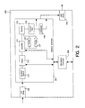
- Figure 2 illustrates a block diagram of an example network device 200 incorporating the teachings of the present invention, in accordance with one embodiment of the present invention.
- network device 200 may well be beneficially incorporated into network 100 as one or more of network edge devices 110, 118 and/or 124.
- network edge device 200 is intended to represent any of a number of alternative network devices commonly used and known in the art.
- the present invention may be practiced in any of a number of alternative embodiments without deviating from the scope of the present invention.
- network device 200 is shown comprising input/output drivers 202 and 208, network interface 204 and controller 206 coupled as shown.
- controller 206 controls the dynamic provision of filters 210 and classifier profiles 222 providing access to the differentiated services offered within the domain of resident core device(s).
- controller 206 may well be incorporated as a functional block of network interface 204 .
- controller 206 may well be remotely located and communicatively coupled to network device 200 and network interface 204 .
- controller 206 is intended to represent any of a number of microprocessors, microcontrollers, programmable logic devices (PLDs), application specific integrated circuits (ASICs) and the like.
- I/O driven 202 and 208 provide the physical interface between network device 200 and the client network and core network, respectively. That is, I/O driver 202 provides an interface supporting data communication (bi-directional) with clients, e.g., client 112 , while I/O driver 208 provides an interface supporting data communication (also bi-directional) with core devices. e.g., core device 108 .
- I/O devices are well known in the art and need not be further described here.
- network interface 204 is shown comprising Decaps/DeMUX unit 210 , filter(s) 212 classifier 214 including profiles 222 , routing unit 216, Encaps/Multiplexer (MUX) 218 and scheduler 220 , each communicatively coupled as shown.
- Decaps/DeMUX 210 receives data packets from a communicatively coupled network via I/O driver 202 and translates the data packets from the communication protocol employed by the network.
- Filter(s) 212 and classifier 214 are employed to identify incoming data traffic adhering to admission policy criteria and marks the data packets with an appropriate routing classification in accordance with a predetermined differentiated services admission policy. That is, filter 212 provides an indication, or trigger, denoting when data packets are received that satisfy filter criteria.
- the filters populating filter(s) 212 are dynamically provisioned on network interface 204 by controller 206 in accordance with a admission control policy, In one embodiment, controller 206 creates and removes specific filters from filter 212 in response to control messages from a remote bandwidth broker, e.g., bandwidth broker 126 .
- controller 206 is a bandwidth broker and creates/removes specific filters from filter 212 on its own accord, in furtherance of a admission control policy. Once in place, filter 212 issues a trigger message to controller 206 when data packets are received satisfying the criteria of an installed filter.
- Classifier 214 functions to classify and mark data packets in accordance with their service level.
- controller 206 updates the installed profiles 222 of classifier 214 such that any data packets received at classifier 214 satisfying at least one profile 222 will be marked in accordance with their subscribed service level.
- the Type of Service (ToS) field in a "header" appended to the data packet is marked to denote an appropriate level of service for transmission of the data packet.
- ToS Type of Service
- header 400 is a byte wide, containing up to eight separate data fields.
- Type of Service (ToS) field 402 is the Type of Service (ToS) field 402 .
- ToS field 402 is a one-bit field. Consequently, ToS field 402 can be marked to differentiate two levels of service, associated with a ToS field 402 entry of '0' or '1'.
- a ToS field 402 populated with a '0' denotes a best-effort service level. Accordingly, when data packets arc received which do not satisfy filter criteria, classifier 214 updates the ToS field 402 of the header appended to such data packers with a '0'.
- receipt of data packets satisfying filter 212 criteria may result in marking the ToS field 402 of the header appended to such data packets with a '1', denoting an expedited forwarding (EF) level of service.
- EF expedited forwarding
- profiles 222 to classifier 214 by controller 206 are closely monitored. That is, profiles 222 are created by controller 206 to satisfy individual flows, e.g., transmission of a number of related data packets, and are summarily removed when the flow no longer exists. Accordingly, a network device such as network device 200 incorporating the teachings of the present invention minimizes the resources dedicated to support filters and classifier profiles by allocating resource to only those filters/classifier profiles currently in use.
- network interface 204 includes routing unit 216 , Encaps/MUX 218 and scheduler 220, as shown.
- Routing unit 216 identifies and marks the data packets with routing information in accordance with the subscribed service level.
- Encaps/MUX 218 places the data packets in the proper format for transmission over the data network.
- Scheduler 220 is used to schedule transmission of data packets through I/O driver 208 in accordance with their subscribed service level, if congestion on the outgoing communication link is detected.
- routing unit 216 , Encaps/MUX 218 and scheduler 220 are typical of those used in the data networking art and, thus, need not be further described.
- controller 206 dynamically controls the provision of filters 212 and classifier profiles 222 in accordance with a differentiated services admission policy, thereby reducing the resources dedicated to support differentiated services.
- example network device 200 incorporating the teachings of the present invention will now be developed with reference to the flow chart depicted in Figure 3 .
- an example method for dynamically controlling the provision of differentiated services in a data network will be developed with reference to the flow chart depicted in Figure 3 , in accordance with one embodiment of the present invention.
- a corporate entity has a number of distributed sites, each having their own respective local area network, e.g., LANs 102,104 and 106 .
- ISP internet service provider
- the corporate entity has contracted with an internet service provider (ISP) to provide premium network services between LAN 102 and LAN 106 between the hours of 9AM and 5PM via its network core device 108 .
- ISP internet service provider
- the example method for controlling the provision of differentiated services of core device 108 begins when data packets are received by a network edge device, e.g., network edge device 110 , with an initial determination of whether a filter corresponding to the received data packets is installed. 301 . If not, a further determination is made of whether a filter need be installed on a network edge device, block 302.
- a network edge device e.g., network edge device 110
- bandwidth broker 126 determines at 9AM that differentiated services have been contracted for between LAN 102 and LAN 106 and issues a setup message to install the appropriate filter an an appropriate network edge device, block 304 . More specifically, bandwidth broker 126 issues a command to controller 206 of network edge device 110 incorporating the teachings of the present invention to install a filter in filter(s) 212 . In one embodiment, the newly installed filter issues a trigger when a source of LAN 102 (e.g., clients 112, 114 and/or 116 ) and a destination of LAN 106 (e.g., clients 120 or 122 ) are denoted in the received data packets.
- a source of LAN 102 e.g., clients 112, 114 and/or 116
- a destination of LAN 106 e.g., clients 120 or 122
- a network edge device incorporating the teachings of the present invention allocates only those resources necessary to support filters that are currently needed, thereby reducing the overall amount of resources required of the network device. If the filter has not expired, however, it continues to monitor received data packets for a "hit", e.g., a received data packet which satisfies the filter criteria (e.g., source from LAN 102 and destination within LAN 106 ), block 310 .
- the received data packets do not satisfy the filter criteria at 310 , they are processed in accordance with the best-effort service paradigm, 312 . That is, if data packets are received which do not adhere to a subscribed service level, the ToS field 402 of the header 400 appended to the data packets is marked by classifier 214 to denote a best-effort service level.
- controller 206 determines whether an appropriate classifier profile 222 is installed in classifier 214 to appropriately mark the data packets in accordance with their subscribed service level, 314. If controller 206 determines that the necessary profile 222 is not installed, controller 206 forwards the trigger notification received from filter 212 to bandwidth broker 126 which corrclates the trigger notification with the appropriate classifier profile, and issues an update message to classifier 214 via controller 206 , block 316 . In one embodiment, in response to receiving a trigger notification from controller 206 , bandwidth broker 126 looks up the received trigger in the admissions policy database to identify an associated classifier profile 222 , 316 .
- classifier 214 marks the ToS field 402 of header 400 appended to the received data packets in accordance with their subscribed service level.
- ToS field 402 is marked to denote a best effort service level, and the data packets an subsequently routed in accordance with their subscribed service level 318 .
- a determination is made of whether transmission is complete. If not, the method continues with block 318 .
- controller 206 makes a determination of whether to remove the classifier profile 222 . In one embodiment, for example, controller 206 makes this determination in accordance with the service level it supports. For example, if profile 222 supports the highest service level, and the filter has not yet expired for that service level, controller 206 maintains the profile to support the service level with minimal delay. If however, profile 222 corresponds to a lower service level, controller 206 may remove the profile, even though the corresponding filter remains in place, to liberate network interface 204 resources. If, in 322 , a determination is made to remove the filter, controller 206 instructs classifier 214 to purge filter 222 , and an update message is sent to bandwidth broker 126 denoting the update. Subsequently, the process continues with
- controller 206 is responsible for the provision of filters 212 and classifier profiles 222 necessary to support differentiated services via network edge device 110 .
- controller 206 relies on the information provided by a remote bandwidth broker 126 or some other policy server.
- controller 206 accesses a co-located admission policy database autonomously. Irregardless of where the admissions policy database is located, access to the differentiated services of core device 108 is dynamically controlled through the selective provision of trigger filters and classifier profiles on network devices, e.g., network device 110 , as appropriate.
- controller 206 may install or remove filter(s) 212 or classifier profiles 222 based on time of day, received network traffic, and any of a number of core network operating parameters (e.g., identified faults, etc.). Indeed, such modifications and alterations to the above description are anticipated within the scope of the present invention.
- Figure 5 illustrates an example two-dimensional admission profile database 500, wherein a network administrator establishes the filters and profiles for admission to be provisioned on appropriate network devices controlling access to differentiated services.
- a network administrator establishes the filters and profiles for admission to be provisioned on appropriate network devices controlling access to differentiated services.
- example admission profile database 500 is shown comprising classifiers 502 and 504 and associated profiles 512-522 differentiated based on time of day indicators 506, 508 and 510.
- the filter established on a network edge device corresponds to an appropriate one or more of classifiers 502 and 504, such that the filter associated with classifier 502 monitors received network traffic for data packets emanating from network A (e.g.. LAN 102 ) destined for network B (e.g., LAN 106 ).
- profile 512 when a hit is received corresponding to classifier 502 during the hours of 9-5, profile 512 will be installed in classifier 214 of network edge device 110 of LAN 102 to mark data packets satisfying the filter criteria in accordance with their subscribed service level.
- packets are marked for expedited forwarding (EF) with a throughput rate of 10Mbps, no burst in accordance with profile 512 .
- EF expedited forwarding
- Packets corresponding to classifier 502 received before 9AM or after 5PM will be marked for best-effort delivery, in accordance with profiles 514 and 516 .
- profiles 518-522 denote service level support for network traffic defined by classifier 504 .
- a network device installs and removes filters and classifier profiles, defined in an admission policy database, on an as-needed, as-authorized basis, thereby limiting the network and device resources dedicated to supporting the differentiated services of an associated data network.
- example network device 600 is similar to that of network device 200 presented above, with the notable exceptions that controller 206 is depicted integrated with network interface 204 and the addition of egress classifier/profiler 602.
- network device 600 controls the provision of differentiated services by dynamically installing/removing trigger filters and classifier profiles in accordance with an admission control policy. In doing so, network device 600, like network device 200 described more fully above, reduces the amount of network and management resources required to support the differentiated services, thereby reducing the overall cost associated with supporting such services.
- teachings of the present invention may well be integrated with a single integrated circuit (not shown). That is, those skilled in the art will appreciate that advances in IC fabrication technology now enable complex systems to be integrated onto a single IC, Thus, in accordance with one embodiment of the present invention, the teachings of the present invention may be practiced within an application specific integrated circuits (ASIC), programmable logic devices (PLD), microcontroller, processor and the like.
- ASIC application specific integrated circuits
- PLD programmable logic devices
- microcontroller microcontroller
Landscapes
- Engineering & Computer Science (AREA)
- Computer Networks & Wireless Communication (AREA)
- Signal Processing (AREA)
- Computer Hardware Design (AREA)
- Computer Security & Cryptography (AREA)
- Computing Systems (AREA)
- General Engineering & Computer Science (AREA)
- Data Exchanges In Wide-Area Networks (AREA)
- Computer And Data Communications (AREA)
Claims (24)
- Eine bei einer Kommunikation zwischen einer Client-Einrichtung und einer fernen Einrichtung verwendete Einrichtung, mit:einer bei der Kommunikation zwischen der Client-Einrichtung und der fernen Einrichtung ein Datenpaket empfangenden Netzwerkschnittstelle (204); undeiner mit der Netzwerkschnittstelle (204) gekoppelten Steuereinrichtung (206) zum dynamischen Erzeugen und Entfernen eines Filters (212) in der Netzwerkschnittstelle, das den Zugang zu verschiedenen Dienstebenen wenigstens teilweise auf der Basis eines Zugriffsprofils (222) steuert, wobei das Filter eine Trigger-Meldung ausgibt, welche anzeigt, dass das empfangene Datenpaket Filterkriterien erfüllt, wobei die Steuereinrichtung bei Empfang der Trigger-Meldung von dem Filter das Zugriffsprofil für eine bestimmte Dienstebene dynamisch installiert.
- Die Einrichtung nach Anspruch 1, wobei das Filter (212) beim Ausgeben der Trigger-Meldung eine Zugriffskontrollentscheidung initiiert, welche eine frühzeitige Zuweisung von Dienstebenenressourcen vermeidet, die noch nicht benötigt werden oder noch nicht autorisiert sind.
- Die Einrichtung nach Anspruch 2, wobei das Filter (212) die Trigger-Meldung unter Verwendung von in dem empfangenen Datenpaket enthaltenen Informationen ausgibt.
- Die Einrichtung nach Anspruch 3, wobei das Filter (212) die Trigger-Meldung unter Verwendung von Paketquelleninformationen und/oder Paketzielinformationen ausgibt.
- Die Einrichtung nach Anspruch 1, wobei das Zugriffsprofil (222, 512-522) in einer kommunikativ gekoppelten fernen Einrichtung gespeichert ist.
- Die Einrichtung nach Anspruch 5, wobei die kommunikativ gekoppelte ferne Einrichtung ein Bandwidth Broker (126) oder ein anderer generischer Policy Server ist.
- Die Einrichtung nach Anspruch 1, wobei das Zugriffsprofil (222, 512-522) in der Netzwerkschnittstelle lokal verfügbar ist.
- Die Einrichtung nach Anspruch 1, wobei die Steuereinrichtung einen Klassifizierer (214) als Reaktion auf das Erfassen eines zugehörigen Trigger-Ereignisses einrichtet, wobei der Klassifizierer (214) das empfangene, die Filterkriterien einhaltende Datenpaket entsprechend dem Zugriffsprofil (222, 500) modifiziert, um eine bestimmte Dienstebene anzuzeigen.
- Die Einrichtung nach Anspruch 8, wobei die Steuereinrichtung das Zugriffsprofil (222) nach dem Abschluss der Übertragung des empfangenen Datenpakets entfernt.
- Die Einrichtung nach Anspruch 8, wobei die Steuereinrichtung das Zugriffsprofil (222) nach einer vorgegebenen Zeitdauer entfernt, wobei Ressourcen freigegeben werden.
- Die Einrichtung nach Anspruch 1, wobei die Steuereinrichtung (206) das Filter (212) einer Netzwerk-Administrations-Policy entsprechend entfernt.
- Die Einrichtung nach Anspruch 11, wobei die Steuereinrichtung (206) das Filter (212) wenigstens teilweise basierend auf der Tageszeit entfernt.
- Die Einrichtung nach Anspruch 1, wobei die Netzwerkschnittstelle (204) aufweist:einen mit dem Filter (212) kommunikativ gekoppelten Klassifizierer (214), um das empfangene Datenpaket zu klassifizieren und mit einer von den verschiedenen Dienstebenen zu markieren, die dem empfangenen Datenpaket zugeordnet sind.
- Die Einrichtung nach Anspruch 13, wobei der Klassifizierer (214) ein Diensttyp(Type of Service-ToS)-Feld (402) des empfangenen Datenpakets markiert, um eine Dienstebene für die Übertragung des Datenpakets anzuzeigen.
- Die Einrichtung nach Anspruch 1, wobei die Steuereinrichtung (206) die von dem Filter (212) empfangene Trigger-Meldung an einen Bandwidth Broker (126) sendet, wenn das Zugriffsprofil (222, 500) nicht installiert ist, so dass der Bandwidth Broker (126) nach dem Suchen in einer Zugriffsprofildatenbank ein geeignetes Zugriffsprofil (222, 500) für die Installation an die Steuereinrichtung sendet.
- Die Einrichtung nach Anspruch 13, wobei die Netzwerkschnittstelle (204) ferner aufweist:eine Routingeinheit (216) zum Identifizieren und Markieren des Datenpakets mit Routinginformationen entsprechend einer vereinbarten Dienstebene.
- Die Einrichtung nach Anspruch 13, wobei die Netzwerkschnittstelle (204) ferner aufweist:einen Encapsulator und Multiplexer (210) zum Platzieren des Datenpakets für die Übertragung.
- Ein Verfahren zum Steuern der Bereitstellung von differenzierten Diensten in einem Datennetzwerk, wobei das Verfahren umfasst:(a) dass ein Filter (212) auf einer Network-Edge-Einrichtung (110, 118, 124) installiert wird, um bei Erfassen eines Filterkriterien einhaltenden Datenpakets eine Trigger-Meldung entsprechend einem Netzwerkzugriffsprofil bereitzustellen; und(b) dass dynamisch ein Zugriffsprofil (222) erzeugt wird, welches bei Empfang der Trigger-Meldung von dem Filter den Zugriff auf eine bestimmte Dienstebene kontrolliert.
- Das Verfahren nach Anspruch 18, ferner umfassend (c), dass das die Filterkriterien einhaltende Datenpaket entsprechend einer vereinbarten Dienstebene markiert wird.
- Das Verfahren nach Anspruch 18, wobei das Zugriffsprofil (222) den Zugriff auf die bestimmte Dienstebene kontrolliert, indem nur dem die Filterkriterien der bestimmten Dienstebene einhaltenden Datenpaket das Fortschreiten erlaubt wird.
- Das Verfahren nach Anspruch 19, wobei das Markieren des Datenpakets umfasst, dass ein logischer Wert in einem Diensttyp(Type of Service-ToS)-Feld eines Headers des Datenpakets gesetzt wird.
- Das Verfahren nach Anspruch 19, ferner umfassend:(e) dass das Datenpaket identifiziert und mit Routinginformationen entsprechend der vereinbarten Dienstebene markiert wird.
- Das Verfahren nach Anspruch 22, ferner umfassend:(f) dass das Datenpaket für die Übertragung plaziert wird.
- Das Verfahren nach Anspruch 18, ferner umfassend:(d2) dass ein Befehl von einem Bandwidth Broker (126) an eine Steuereinrichtung (206) der Network-Edge-Einrichtung (110, 118, 124) ausgegeben wird, um das Filter (212) als Reaktion auf das Bestimmen, ob das empfangene Datenpaket die Filterkriterien erfüllt, dynamisch zu installieren oder zu entfernen.
Applications Claiming Priority (2)
| Application Number | Priority Date | Filing Date | Title |
|---|---|---|---|
| US09/222,340 US20020188720A1 (en) | 1998-12-28 | 1998-12-28 | Method and apparatus for dynamically controlling the provision of differentiated services |
| US222340 | 1998-12-28 |
Publications (3)
| Publication Number | Publication Date |
|---|---|
| EP1024642A2 EP1024642A2 (de) | 2000-08-02 |
| EP1024642A3 EP1024642A3 (de) | 2002-06-19 |
| EP1024642B1 true EP1024642B1 (de) | 2005-08-03 |
Family
ID=22831815
Family Applications (1)
| Application Number | Title | Priority Date | Filing Date |
|---|---|---|---|
| EP99310504A Expired - Lifetime EP1024642B1 (de) | 1998-12-28 | 1999-12-23 | Verfahren und Vorrichtung zur dynamischen Steuerung der Bereitstellung von differenzierter Diensten |
Country Status (4)
| Country | Link |
|---|---|
| US (1) | US20020188720A1 (de) |
| EP (1) | EP1024642B1 (de) |
| CA (1) | CA2293130C (de) |
| DE (1) | DE69926477T2 (de) |
Families Citing this family (26)
| Publication number | Priority date | Publication date | Assignee | Title |
|---|---|---|---|---|
| US6701432B1 (en) * | 1999-04-01 | 2004-03-02 | Netscreen Technologies, Inc. | Firewall including local bus |
| US7107612B1 (en) | 1999-04-01 | 2006-09-12 | Juniper Networks, Inc. | Method, apparatus and computer program product for a network firewall |
| EP2802189A3 (de) * | 1999-08-12 | 2015-03-18 | Elad Barkan | Zusatzbasisstation zur Erweiterung eines zellularen netzes |
| JP3386117B2 (ja) * | 2000-01-11 | 2003-03-17 | 日本電気株式会社 | マルチレイヤクラス識別通信装置と通信装置 |
| US6922685B2 (en) | 2000-05-22 | 2005-07-26 | Mci, Inc. | Method and system for managing partitioned data resources |
| US7401131B2 (en) * | 2000-05-22 | 2008-07-15 | Verizon Business Global Llc | Method and system for implementing improved containers in a global ecosystem of interrelated services |
| US7464163B1 (en) * | 2000-07-27 | 2008-12-09 | International Business Machines Corporation | Service provisioning via attribute-based subscription |
| US7886054B1 (en) | 2000-10-11 | 2011-02-08 | Siddhartha Nag | Graphical user interface (GUI) for administering a network implementing media aggregation |
| US7788354B2 (en) | 2000-07-28 | 2010-08-31 | Siddhartha Nag | End-to-end service quality in a voice over Internet Protocol (VoIP) Network |
| US7013338B1 (en) | 2000-07-28 | 2006-03-14 | Prominence Networks, Inc. | Multiplexing several individual application sessions over a pre-allocated reservation protocol session |
| US7774468B1 (en) * | 2000-07-28 | 2010-08-10 | Siddhartha Nag | Network traffic admission control |
| JP4082858B2 (ja) * | 2000-10-30 | 2008-04-30 | 富士通株式会社 | ネットワークアクセス制御方法及びそれを用いたネットワークシステム及びそれを構成する装置 |
| US7028179B2 (en) | 2001-07-03 | 2006-04-11 | Intel Corporation | Apparatus and method for secure, automated response to distributed denial of service attacks |
| US8611363B2 (en) | 2002-05-06 | 2013-12-17 | Adtran, Inc. | Logical port system and method |
| FR2841713B1 (fr) * | 2002-06-28 | 2005-04-15 | France Telecom | Systeme d'acces a un reseau d'informations offrant des services personnalises |
| US6968374B2 (en) | 2002-07-03 | 2005-11-22 | Telefonaktiebolaget Lm Ericsson (Publ) | Quality of service (QOS) mechanism in an internet protocol (IP) network |
| US7508825B2 (en) * | 2002-08-05 | 2009-03-24 | Intel Corporation | Data packet classification |
| US7366174B2 (en) * | 2002-12-17 | 2008-04-29 | Lucent Technologies Inc. | Adaptive classification of network traffic |
| US7558844B1 (en) * | 2003-05-06 | 2009-07-07 | Juniper Networks, Inc. | Systems and methods for implementing dynamic subscriber interfaces |
| AU2003264031A1 (en) * | 2003-08-08 | 2005-03-07 | Luminous Networks, Inc. | Multiple services provisioning in a packet forwarding device with logical ports |
| US20050050243A1 (en) * | 2003-08-29 | 2005-03-03 | Clark Stacey A. | Modified core-edge topology for a fibre channel network |
| US8428074B2 (en) | 2005-04-29 | 2013-04-23 | Prom Ks Mgmt Limited Liability Company | Back-to back H.323 proxy gatekeeper |
| US20100030905A1 (en) * | 2006-12-19 | 2010-02-04 | Ioannis Fikouras | Technique for providing services in a service provisioning network |
| US9379998B2 (en) | 2014-02-07 | 2016-06-28 | International Business Machines Corporation | Symmetric coherent request/response policy enforcement |
| US10673704B2 (en) * | 2017-02-15 | 2020-06-02 | Arista Networks, Inc. | System and method of dynamic hardware policer allocation |
| US11695850B2 (en) | 2019-05-10 | 2023-07-04 | Samsung Electronics Co., Ltd. | Method and edge enabler server for providing dynamic information to edge enabler client running in UE |
Family Cites Families (50)
| Publication number | Priority date | Publication date | Assignee | Title |
|---|---|---|---|---|
| US5321837A (en) * | 1991-10-11 | 1994-06-14 | International Business Machines Corporation | Event handling mechanism having a process and an action association process |
| US5473607A (en) * | 1993-08-09 | 1995-12-05 | Grand Junction Networks, Inc. | Packet filtering for data networks |
| US5485455A (en) * | 1994-01-28 | 1996-01-16 | Cabletron Systems, Inc. | Network having secure fast packet switching and guaranteed quality of service |
| US5623601A (en) * | 1994-11-18 | 1997-04-22 | Milkway Networks Corporation | Apparatus and method for providing a secure gateway for communication and data exchanges between networks |
| US5777549A (en) * | 1995-03-29 | 1998-07-07 | Cabletron Systems, Inc. | Method and apparatus for policy-based alarm notification in a distributed network management environment |
| US5881315A (en) * | 1995-08-18 | 1999-03-09 | International Business Machines Corporation | Queue management for distributed computing environment to deliver events to interested consumers even when events are generated faster than consumers can receive |
| US5793954A (en) * | 1995-12-20 | 1998-08-11 | Nb Networks | System and method for general purpose network analysis |
| US5892924A (en) * | 1996-01-31 | 1999-04-06 | Ipsilon Networks, Inc. | Method and apparatus for dynamically shifting between routing and switching packets in a transmission network |
| US5721825A (en) * | 1996-03-15 | 1998-02-24 | Netvision, Inc. | System and method for global event notification and delivery in a distributed computing environment |
| US6510151B1 (en) * | 1996-09-19 | 2003-01-21 | Enterasys Networks, Inc. | Packet filtering in connection-based switching networks |
| US6046980A (en) * | 1996-12-09 | 2000-04-04 | Packeteer, Inc. | System for managing flow bandwidth utilization at network, transport and application layers in store and forward network |
| US5848233A (en) * | 1996-12-09 | 1998-12-08 | Sun Microsystems, Inc. | Method and apparatus for dynamic packet filter assignment |
| US6198728B1 (en) * | 1996-12-19 | 2001-03-06 | Phillips Electronics North America Corp. | Medium access control (MAC) protocol for wireless ATM |
| US6009475A (en) * | 1996-12-23 | 1999-12-28 | International Business Machines Corporation | Filter rule validation and administration for firewalls |
| US6408336B1 (en) * | 1997-03-10 | 2002-06-18 | David S. Schneider | Distributed administration of access to information |
| US6105027A (en) * | 1997-03-10 | 2000-08-15 | Internet Dynamics, Inc. | Techniques for eliminating redundant access checking by access filters |
| US5983270A (en) * | 1997-03-11 | 1999-11-09 | Sequel Technology Corporation | Method and apparatus for managing internetwork and intranetwork activity |
| US5940390A (en) * | 1997-04-10 | 1999-08-17 | Cisco Technology, Inc. | Mechanism for conveying data prioritization information among heterogeneous nodes of a computer network |
| US6067569A (en) * | 1997-07-10 | 2000-05-23 | Microsoft Corporation | Fast-forwarding and filtering of network packets in a computer system |
| US6104700A (en) * | 1997-08-29 | 2000-08-15 | Extreme Networks | Policy based quality of service |
| CA2242219A1 (en) * | 1997-10-03 | 1999-04-03 | Newbridge Networks Corporation | Classes of service in an mpoa network |
| US6591299B2 (en) * | 1997-11-25 | 2003-07-08 | Packeteer, Inc. | Method for automatically classifying traffic with enhanced hierarchy in a packet communications network |
| US6412000B1 (en) * | 1997-11-25 | 2002-06-25 | Packeteer, Inc. | Method for automatically classifying traffic in a packet communications network |
| US6330610B1 (en) * | 1997-12-04 | 2001-12-11 | Eric E. Docter | Multi-stage data filtering system employing multiple filtering criteria |
| US6031841A (en) * | 1997-12-23 | 2000-02-29 | Mediaone Group, Inc. | RSVP support for upstream traffic |
| US6463068B1 (en) * | 1997-12-31 | 2002-10-08 | Cisco Technologies, Inc. | Router with class of service mapping |
| US6230271B1 (en) * | 1998-01-20 | 2001-05-08 | Pilot Network Services, Inc. | Dynamic policy-based apparatus for wide-range configurable network service authentication and access control using a fixed-path hardware configuration |
| US6341130B1 (en) * | 1998-02-09 | 2002-01-22 | Lucent Technologies, Inc. | Packet classification method and apparatus employing two fields |
| US6484261B1 (en) * | 1998-02-17 | 2002-11-19 | Cisco Technology, Inc. | Graphical network security policy management |
| US6141686A (en) * | 1998-03-13 | 2000-10-31 | Deterministic Networks, Inc. | Client-side application-classifier gathering network-traffic statistics and application and user names using extensible-service provider plugin for policy-based network control |
| US6148336A (en) * | 1998-03-13 | 2000-11-14 | Deterministic Networks, Inc. | Ordering of multiple plugin applications using extensible layered service provider with network traffic filtering |
| US6459682B1 (en) * | 1998-04-07 | 2002-10-01 | International Business Machines Corporation | Architecture for supporting service level agreements in an IP network |
| US6130924A (en) * | 1998-04-20 | 2000-10-10 | Sun Microsystems, Inc. | Method and apparatus for administrative control over data transmission using dynamic filtering in a multicast network |
| US6449256B1 (en) * | 1998-05-07 | 2002-09-10 | Washington University | Fast level four switching using crossproducting |
| US6167047A (en) * | 1998-05-18 | 2000-12-26 | Solidum Systems Corp. | Packet classification state machine |
| US6353616B1 (en) * | 1998-05-21 | 2002-03-05 | Lucent Technologies Inc. | Adaptive processor schedulor and method for reservation protocol message processing |
| US6209101B1 (en) * | 1998-07-17 | 2001-03-27 | Secure Computing Corporation | Adaptive security system having a hierarchy of security servers |
| US6269382B1 (en) * | 1998-08-31 | 2001-07-31 | Microsoft Corporation | Systems and methods for migration and recall of data from local and remote storage |
| US6570875B1 (en) * | 1998-10-13 | 2003-05-27 | Intel Corporation | Automatic filtering and creation of virtual LANs among a plurality of switch ports |
| US6286052B1 (en) * | 1998-12-04 | 2001-09-04 | Cisco Technology, Inc. | Method and apparatus for identifying network data traffic flows and for applying quality of service treatments to the flows |
| US6167445A (en) * | 1998-10-26 | 2000-12-26 | Cisco Technology, Inc. | Method and apparatus for defining and implementing high-level quality of service policies in computer networks |
| US6519636B2 (en) * | 1998-10-28 | 2003-02-11 | International Business Machines Corporation | Efficient classification, manipulation, and control of network transmissions by associating network flows with rule based functions |
| US6581093B1 (en) * | 1998-10-29 | 2003-06-17 | International Business Machines Corporation | Policy validation in a LDAP directory |
| US6714517B1 (en) * | 1998-11-10 | 2004-03-30 | Extreme Networks | Method and apparatus for interconnection of packet switches with guaranteed bandwidth |
| US6510164B1 (en) * | 1998-11-16 | 2003-01-21 | Sun Microsystems, Inc. | User-level dedicated interface for IP applications in a data packet switching and load balancing system |
| US6850528B1 (en) * | 1998-11-20 | 2005-02-01 | Microsoft Corporation | System and method for maintaining network system information |
| US6625150B1 (en) * | 1998-12-17 | 2003-09-23 | Watchguard Technologies, Inc. | Policy engine architecture |
| US6643260B1 (en) * | 1998-12-18 | 2003-11-04 | Cisco Technology, Inc. | Method and apparatus for implementing a quality of service policy in a data communications network |
| US6549882B1 (en) * | 1998-12-21 | 2003-04-15 | Cisco Technology, Inc. | Mechanisms for providing and using a scripting language for flexibly simulationg a plurality of different network protocols |
| US6609153B1 (en) * | 1998-12-24 | 2003-08-19 | Redback Networks Inc. | Domain isolation through virtual network machines |
-
1998
- 1998-12-28 US US09/222,340 patent/US20020188720A1/en not_active Abandoned
-
1999
- 1999-12-23 DE DE69926477T patent/DE69926477T2/de not_active Expired - Lifetime
- 1999-12-23 EP EP99310504A patent/EP1024642B1/de not_active Expired - Lifetime
- 1999-12-24 CA CA2293130A patent/CA2293130C/en not_active Expired - Fee Related
Also Published As
| Publication number | Publication date |
|---|---|
| CA2293130A1 (en) | 2000-06-28 |
| US20020188720A1 (en) | 2002-12-12 |
| DE69926477T2 (de) | 2006-04-20 |
| EP1024642A3 (de) | 2002-06-19 |
| CA2293130C (en) | 2010-09-28 |
| DE69926477D1 (de) | 2005-09-08 |
| EP1024642A2 (de) | 2000-08-02 |
Similar Documents
| Publication | Publication Date | Title |
|---|---|---|
| CA2293130C (en) | Method and apparatus for dynamically controlling the provision of differentiated services | |
| US6826147B1 (en) | Method and apparatus for aggregate flow control in a differentiated services network | |
| US8861358B2 (en) | Applying router quality of service on a cable modem interface on a per-service-flow basis | |
| JP4520705B2 (ja) | 通信システム及び通信方法 | |
| US7778176B2 (en) | Methods, apparatuses and systems facilitating concurrent classification and control of tunneled and non-tunneled network traffic | |
| US7505408B1 (en) | Automatically applying bi-directional quality of service treatment to network data flows | |
| US7096260B1 (en) | Marking network data packets with differentiated services codepoints based on network load | |
| US8767547B2 (en) | Flow state aware QoS management without user signaling | |
| US7486696B2 (en) | System and method for providing bandwidth management for VPNs | |
| AU703228B2 (en) | Data link interface for packet-switched network | |
| US7907529B2 (en) | Communications networks | |
| US20140269316A1 (en) | Method for maintaining differentiated services data flow at a network device implementing redundant packet discard security techniques | |
| US20100135287A1 (en) | Process for prioritized end-to-end secure data protection | |
| JP2004532545A (ja) | データネットワークにおけるルータ間のクラス毎の資源のポリシに基づく同期。 | |
| WO2002075554A1 (en) | Pool-based resource management in a data network | |
| WO2000060826A1 (en) | Packet classifier and converter | |
| JP2004530340A (ja) | データネットワークにおけるエッジに基づくフローごとのQoS許可制御 | |
| JP2004289792A (ja) | データ伝送制御を使用するサービス品質保証システム | |
| WO2004092927A2 (en) | Call admission control/session management based on n source to destination severity levels for ip networks | |
| JP2005502275A (ja) | Ip通信網における方法及び装置 | |
| US20040174889A1 (en) | Network system and communication band control method thereof | |
| HUE028211T2 (en) | Manage network traffic through a fixed address | |
| EP2405609A2 (de) | System und Verfahren zur Überwachung und Optimierung von Verkehr in MPLS-Diffserv-Netzwerken | |
| Terzis et al. | A prototype implementation of the two-tier architecture for differentiated services | |
| JP2009105949A (ja) | QoS制御を実行することが可能な端末 |
Legal Events
| Date | Code | Title | Description |
|---|---|---|---|
| PUAI | Public reference made under article 153(3) epc to a published international application that has entered the european phase |
Free format text: ORIGINAL CODE: 0009012 |
|
| AK | Designated contracting states |
Kind code of ref document: A2 Designated state(s): AT BE CH CY DE DK ES FI FR GB GR IE IT LI LU MC NL PT SE |
|
| AX | Request for extension of the european patent |
Free format text: AL;LT;LV;MK;RO;SI |
|
| RAP1 | Party data changed (applicant data changed or rights of an application transferred) |
Owner name: NORTEL NETWORKS LIMITED |
|
| PUAL | Search report despatched |
Free format text: ORIGINAL CODE: 0009013 |
|
| AK | Designated contracting states |
Kind code of ref document: A3 Designated state(s): AT BE CH CY DE DK ES FI FR GB GR IE IT LI LU MC NL PT SE |
|
| AX | Request for extension of the european patent |
Free format text: AL;LT;LV;MK;RO;SI |
|
| 17P | Request for examination filed |
Effective date: 20021217 |
|
| AKX | Designation fees paid |
Designated state(s): DE GB |
|
| RBV | Designated contracting states (corrected) |
Designated state(s): DE FR GB |
|
| 17Q | First examination report despatched |
Effective date: 20030718 |
|
| RAP1 | Party data changed (applicant data changed or rights of an application transferred) |
Owner name: NORTEL NETWORKS LIMITED |
|
| GRAP | Despatch of communication of intention to grant a patent |
Free format text: ORIGINAL CODE: EPIDOSNIGR1 |
|
| GRAS | Grant fee paid |
Free format text: ORIGINAL CODE: EPIDOSNIGR3 |
|
| GRAA | (expected) grant |
Free format text: ORIGINAL CODE: 0009210 |
|
| AK | Designated contracting states |
Kind code of ref document: B1 Designated state(s): DE FR GB |
|
| REG | Reference to a national code |
Ref country code: GB Ref legal event code: FG4D |
|
| REF | Corresponds to: |
Ref document number: 69926477 Country of ref document: DE Date of ref document: 20050908 Kind code of ref document: P |
|
| ET | Fr: translation filed | ||
| PLBE | No opposition filed within time limit |
Free format text: ORIGINAL CODE: 0009261 |
|
| STAA | Information on the status of an ep patent application or granted ep patent |
Free format text: STATUS: NO OPPOSITION FILED WITHIN TIME LIMIT |
|
| 26N | No opposition filed |
Effective date: 20060504 |
|
| PGFP | Annual fee paid to national office [announced via postgrant information from national office to epo] |
Ref country code: DE Payment date: 20091230 Year of fee payment: 11 |
|
| REG | Reference to a national code |
Ref country code: GB Ref legal event code: 732E Free format text: REGISTERED BETWEEN 20101209 AND 20101215 |
|
| REG | Reference to a national code |
Ref country code: FR Ref legal event code: TP |
|
| REG | Reference to a national code |
Ref country code: DE Ref legal event code: R082 Ref document number: 69926477 Country of ref document: DE Representative=s name: PATENTANWAELTE WALLACH, KOCH, DR. HAIBACH, FEL, DE Effective date: 20110919 Ref country code: DE Ref legal event code: R082 Ref document number: 69926477 Country of ref document: DE Representative=s name: PATENTANWAELTE WALLACH, KOCH & PARTNER, DE Effective date: 20110919 Ref country code: DE Ref legal event code: R081 Ref document number: 69926477 Country of ref document: DE Owner name: AVAYA INC. (N.D.GES.D. STAATES DELAWARE), BASK, US Free format text: FORMER OWNER: NORTEL NETWORKS LTD., ST. LAURENT, QUEBEC, CA Effective date: 20110919 Ref country code: DE Ref legal event code: R081 Ref document number: 69926477 Country of ref document: DE Owner name: AVAYA INC. (N.D.GES.D. STAATES DELAWARE), US Free format text: FORMER OWNER: NORTEL NETWORKS LTD., ST. LAURENT, CA Effective date: 20110919 |
|
| REG | Reference to a national code |
Ref country code: DE Ref legal event code: R119 Ref document number: 69926477 Country of ref document: DE Effective date: 20110701 |
|
| PG25 | Lapsed in a contracting state [announced via postgrant information from national office to epo] |
Ref country code: DE Free format text: LAPSE BECAUSE OF NON-PAYMENT OF DUE FEES Effective date: 20110701 |
|
| PGFP | Annual fee paid to national office [announced via postgrant information from national office to epo] |
Ref country code: FR Payment date: 20130107 Year of fee payment: 14 |
|
| PGFP | Annual fee paid to national office [announced via postgrant information from national office to epo] |
Ref country code: GB Payment date: 20131218 Year of fee payment: 15 |
|
| REG | Reference to a national code |
Ref country code: FR Ref legal event code: ST Effective date: 20140829 |
|
| PG25 | Lapsed in a contracting state [announced via postgrant information from national office to epo] |
Ref country code: FR Free format text: LAPSE BECAUSE OF NON-PAYMENT OF DUE FEES Effective date: 20131231 |
|
| GBPC | Gb: european patent ceased through non-payment of renewal fee |
Effective date: 20141223 |
|
| PG25 | Lapsed in a contracting state [announced via postgrant information from national office to epo] |
Ref country code: GB Free format text: LAPSE BECAUSE OF NON-PAYMENT OF DUE FEES Effective date: 20141223 |