EP1024482A1 - Actuator base for optical pickup and method for manufacturing the same - Google Patents
Actuator base for optical pickup and method for manufacturing the same Download PDFInfo
- Publication number
- EP1024482A1 EP1024482A1 EP00300682A EP00300682A EP1024482A1 EP 1024482 A1 EP1024482 A1 EP 1024482A1 EP 00300682 A EP00300682 A EP 00300682A EP 00300682 A EP00300682 A EP 00300682A EP 1024482 A1 EP1024482 A1 EP 1024482A1
- Authority
- EP
- European Patent Office
- Prior art keywords
- yoke
- pair
- actuator base
- portions
- punching
- Prior art date
- Legal status (The legal status is an assumption and is not a legal conclusion. Google has not performed a legal analysis and makes no representation as to the accuracy of the status listed.)
- Withdrawn
Links
- 230000003287 optical effect Effects 0.000 title claims description 44
- 238000000034 method Methods 0.000 title claims description 15
- 238000004519 manufacturing process Methods 0.000 title claims description 13
- 238000004080 punching Methods 0.000 claims abstract description 23
- 238000011161 development Methods 0.000 claims abstract description 9
- 238000005452 bending Methods 0.000 claims description 11
- 239000000696 magnetic material Substances 0.000 claims description 4
- 239000007769 metal material Substances 0.000 claims description 3
- 230000018109 developmental process Effects 0.000 description 7
- 239000000725 suspension Substances 0.000 description 7
- 230000001133 acceleration Effects 0.000 description 3
- 230000004907 flux Effects 0.000 description 3
- 238000003860 storage Methods 0.000 description 3
- 238000013016 damping Methods 0.000 description 2
- 239000000463 material Substances 0.000 description 2
- 230000002093 peripheral effect Effects 0.000 description 2
- 229910000831 Steel Inorganic materials 0.000 description 1
- 230000001678 irradiating effect Effects 0.000 description 1
- 230000005855 radiation Effects 0.000 description 1
- 239000011347 resin Substances 0.000 description 1
- 229920005989 resin Polymers 0.000 description 1
- 238000005476 soldering Methods 0.000 description 1
- 239000010959 steel Substances 0.000 description 1
Images


Classifications
-
- G—PHYSICS
- G11—INFORMATION STORAGE
- G11B—INFORMATION STORAGE BASED ON RELATIVE MOVEMENT BETWEEN RECORD CARRIER AND TRANSDUCER
- G11B7/00—Recording or reproducing by optical means, e.g. recording using a thermal beam of optical radiation by modifying optical properties or the physical structure, reproducing using an optical beam at lower power by sensing optical properties; Record carriers therefor
- G11B7/08—Disposition or mounting of heads or light sources relatively to record carriers
- G11B7/09—Disposition or mounting of heads or light sources relatively to record carriers with provision for moving the light beam or focus plane for the purpose of maintaining alignment of the light beam relative to the record carrier during transducing operation, e.g. to compensate for surface irregularities of the latter or for track following
- G11B7/0925—Electromechanical actuators for lens positioning
- G11B7/0933—Details of stationary parts
-
- G—PHYSICS
- G11—INFORMATION STORAGE
- G11B—INFORMATION STORAGE BASED ON RELATIVE MOVEMENT BETWEEN RECORD CARRIER AND TRANSDUCER
- G11B7/00—Recording or reproducing by optical means, e.g. recording using a thermal beam of optical radiation by modifying optical properties or the physical structure, reproducing using an optical beam at lower power by sensing optical properties; Record carriers therefor
- G11B7/12—Heads, e.g. forming of the optical beam spot or modulation of the optical beam
- G11B7/22—Apparatus or processes for the manufacture of optical heads, e.g. assembly
Definitions
- the present invention relates to an optical pickup for recording/reproducing information in an optical recording medium such as an optical disc, and in particular relates to a manufacturing method of an actuator base for the optical pickup.
- a storage device is one of the peripheral devices.
- the storage device has various kinds, and a CD-R (compact disc recordable) device is one of them.
- the CD-R device is able to be additionally written upon and has compatibility with a CD-ROM or an audio CD (CD-DA).
- CD-DA audio CD
- an exclusive writing device and application for writing are needed while a general CD-ROM driver can be used for reading information from the CD-R device.
- additional information can be repeatedly written therein.
- such optical pickup comprises a laser beam source for emitting a laser beam and an optical system for leading the emitted laser beam to a recording medium such as an optical disc.
- a laser beam source for emitting a laser beam
- an optical system for leading the emitted laser beam to a recording medium such as an optical disc.
- the power level of a laser beam emitted from the laser beam source is required for switching between levels in reading information and in writing it. The reason is that information writing is performed by forming pits on a recording layer of the optical disc by radiation with the laser beam.
- the power level of the laser beam emitted from the laser beam source during writing information is larger than that during reading it. For example, the power level during writing information is roughly 10 to 20 times larger than that during reading it.
- the optical pickup comprises an optical base, a lens holder, a damper base, and an actuator base.
- the lens holder includes an objective lens, a tracking coil, and a focusing coil.
- the actuator base is used for accommodating the lens holder and the damper base.
- the actuator base is formed of a metallic plate of a magnetic material. This is because function as yoke is demanded from part of the actuator base.
- the part of the actuator base functioning as the yoke is required to have a predetermined thickness.
- An optical pickup applicable to the present invention comprises a lens holder holding an objective lens for the optical pickup, a damper base for supporting the lens holder movably in vertical and horizontal directions via plural pieces of suspension wire, and an actuator base having a supporting block for fixing the damper base.
- the actuator base is formed of a magnetic and metallic material and comprises an inverted U-shaped pair of yoke portions for holding permanent magnets at positions corresponding to both sides of the lens holder.
- a method for manufacturing an actuator base comprises the steps of having an elongated rectangular frame portion in the actuator base, forming the pair of yoke portions so as to exit between longitudinal sides of a frame portion opposing each other in the frame portion, and punching the frame portion and the pair of yoke portions unitarily from a metallic plate, wherein the step of punching the frame portion and the pair of yoke portions are performed based on a development in which the pair of yoke portions are distant from each other in advance.
- Another aspect of the invention is a metallic plate punched to form unitarily a frame portion and a pair of yoke portions of an optical base for an optical pickup.
- the metallic plate after punching and before bending into usable form has two parallel frame segments connected by a connecting segment.
- a yoke segment extends from each frame segment in a direction generally normal to the respective frame segment, and the two yoke segments extend in opposite directions from each other.
- Each yoke segment has an arm extending generally normal to the frame segments, and each arm has a pair of flaps, each flap extending from an opposite side of the arm.
- the metallic plate is configured by the punching such that when the metallic plate is bent into usable form, with a portion of the arms of the two yoke segments being brought into a coplanar relation, the distance between the arms of the two yoke segments is less than the aggregate length of their adjacent respective flaps. Portions of the plate forming the two yoke segments preferably have the same thickness.
- the method for manufacturing the actuator base for an optical pickup comprises the steps of punching the metallic plate, and punching the metallic plate into the usable form.
- the optical pickup 1 comprises an optical base 2, a lens holder 3, a damper base 4, and an actuator base 5.
- the lens holder 3 comprises an objective lens 3-1, a tracking coil (not shown), and a focusing coil (not shown).
- the actuator base 5 is used for accommodating the lens holder 3 and the damper base 4.
- the optical pickup 1 also comprises a laser unit 11 as a laser-beam source for emitting a laser beam.
- the surface of the optical disc (CD-R) is irradiated with the laser beam emitted from the laser unit 11 through a diffraction grating, a beam splitter, a collimating lens, and the objective lens 3-1.
- the optical disc is an optical storage medium.
- the laser beam reflected from the optical disc is launched into a photodiode (PD) through the objective lens 3-1, the collimating lens, and the beam splitter.
- the photodiode is a light-receiving device for receiving the laser beam reflected from the optical disc.
- the laser unit 11 and an optical system such as the beam splitter are held by the optical base 2.
- the optical base 2 is fixed to a casing (not shown) of an optical disc drive.
- a circuit board 15 is fixed to one side of the optical base 2.
- the circuit board 15 is electrically connected to other circuit elements (not shown) of the optical disc drive by flexible cables 16 connected thereto.
- the lens holder 3 is connected to the damper base 4 via plural pieces of suspension wire 6.
- the assembly of these parts is accommodated in the actuator base 5.
- a portion of the actuator base 5 is a yoke 7.
- a permanent magnet (to be described later) is combined with the yoke 7.
- the actuator base 5 is of an elongated-rectangular frame-shaped structure formed of a metallic and magnetic material.
- One side of the frame-shaped structure has a receiving portion (not shown) for the damper base 4.
- This receiving portion has a supporting block 5-1 for fixing the damper base 4.
- the supporting block 5-1 is unitarily formed with the actuator base 5.
- Approximately semi-circular protrusions 5-2 are respectively formed on both longitudinal side-walls of the frame-shaped structure.
- the protrusions 5-2 are supported by supporting portions 2-1 disposed in the optical base 2.
- a damper base cover 4-1 formed of a transparent resin material is fixed to the damper base 4.
- fixing portions 4-2 each for fixing one end of pieces of the suspension wire 6 are disposed.
- a space between the damper base 4 and the damper base cover 4-1 is filled with a vibration-damping material (not shown) for damping the vibration of the suspension wires 6.
- a flexible wiring board 8 for connecting to end portions of the suspension wire 6 by soldering is disposed on the rear wall of the damper base 4.
- the damper base 4 is fixed in an inserted state into a space between both side-walls of the actuator base 5 and the supporting block 5-1.
- the damper base 4 is secured by a screw (or a bolt) 9 and a nut 10 so as to pinch the supporting block 5-1 and a portion of the damper base 4.
- the damper base 4 is rotatable about the screw 9. This is for the purpose of skewing adjustment.
- the suspension wires 6 are secured to the damper base 4. That is, the lens holder 3 and the damper base 4 are accommodated in the actuator base 5 to be fixed thereto in a state of an assembly connected by the suspension wires 6.
- Such an optical pickup is disclosed in Japanese Patent Application No. 10-337509, for example.
- the actuator base 5 of the optical pickup shown in Fig. 1 is in a shape shown in Figs. 2 and 3.
- the actuator base 5 shown in Figs. 1 to 3 is used for driving the lens holder 3.
- the lens holder 3 has the objective lens 3-1 and is coiled by the tracking coil and the focusing coil as well. Accordingly, permanent magnets 20 are assembled on both sides of the actuator base 5 in the longitudinal direction with the lens holder 3 in between, respectively.
- Two inverted U-shaped portions are formed in the actuator base 5 so as to be disposed between both of the longitudinal side-walls thereof.
- Each permanent magnet 20 is assembled to an inverted U-shaped portion.
- the two permanent magnets 20 form two magnetic circuits with the actuator base 5.
- the inverted U-shaped portion has two plate portions extending downwardly. In the two plate portions, one disposed farther from the lens holder 3 is called a back yoke 5-11 while the other disposed closer to the lens holder 3 is called an opposing yoke 5-12.
- a function of such magnetic circuit is also disclosed in Japanese Unexamined Patent Publication No. 10-334485, for example.
- the actuator base 5 a sufficient thickness is needed so that magnetic flux cannot leak from the inverted U-shaped portion.
- the objective lens 3-1 and the lens holder 3 are preferably as small as possible so as to obtain a high-degree of acceleration during driving of the lens holder 3. Therefore, it is necessary to reduce the distance between the opposing yokes 5-12 of the two magnetic circuits. If we set the sum of respective lengths of two opposing yokes 5-12 to be "2B", the sum of lengths "2B" becomes longer than the distance "A" between the two opposing yokes 5-12 shown in Fig. 2. This means that the actuator base 5 cannot be manufactured by press punching of one steel plate as shown in Fig. 3.
- Both magnetic circuits are made as separate parts and thereafter fixed together.
- Figs. 6 and 7 are a plan view and a side view of an actuator base obtained according to the present invention, respectively.
- the actuator base obtained according to the present invention can be applied to the optical pickup shown in Fig. 1.
- An actuator base 30 is formed of a magnetic and metallic plate and comprises an elongated rectangular frame portion 31.
- the actuator base 30 also comprises a pair of yoke portions 32 disposed between longitudinal sides 31-1 opposing each other in the frame portion 31 and at the positions corresponding to both sides of the lens holder (shown in Fig. 1 as numeral 3).
- Each yoke portion 32 is used to hold a permanent magnet and has an inverted U-shape.
- Each yoke portion 32 exists so as to be disposed between the longitudinal sides 31-1 which are opposing each other.
- the manufacturing method according to the embodiment has a feature that the frame portion 31 and a pair of yoke portions 32 can be unitarily or integrally formed by punching of one metallic plate.
- the method has a feature that punching is performed based on a development in which the pair of yoke portions are distant from each other.
- An example of developments of the actuator base 30 is shown in Fig. 5.
- two longitudinal sides 31-1 for forming the frame portion 31 are connected together by a front-end portion 31-2 in the direction opposite to the damper base (shown in Fig. 1 as numeral 4).
- a block 31-3 for forming one of the pair of yoke portions 32 is extending in the perpendicular direction.
- the block 31-3 comprises plate portions 31-3a, 31-3b, and 31-3c.
- the plate portion 31-3a forms a ceiling portion of the inverted U-shape portion.
- the plate portion 31-3b is to be the back yoke while the plate portion 31-3c is to be the opposing yoke.
- a block 31-4 forming the other of the pair of yoke portions 32 is extending in the perpendicular direction.
- the block 31-4 comprises plate portions 31-4a, 31-4b, 31-4c, 31-4d, and 31-4e.
- the plate portion 31-4a forms a ceiling portion of the inverted U-shape portion.
- the plate portion 31-4b is to be the back yoke while the plate portion 31-4c is to be the opposing yoke.
- the plate portions 31-4d and 31-4e form an approximate U-shaped portion along with the plate portion 31-4b so as to secure a space for holding the damper base.
- a hole 31-41 for inserting a screw is formed in the plate portion 31-4e.
- a hole 31-42 for inserting a screw is formed by drawing.
- Approximately semi-circular protrusions 31-11 corresponding to the approximately semi-circular protrusions 5-2 described in Fig. 1 are formed by drawing in the two longitudinal sides 31-1, respectively.
- the plate portions of the blocks 31-3 and 31-4 for forming the yoke portions 32 have the same thickness.
- Fig. 5 the portion indicated as "BENDING UPWARDLY" on a dashed line means that bending is to be performed at about 90° upwardly viewing the drawing.
- the plate portion 31-3a is bent at 90° upwardly.
- the plate portion 31-4d is bent at 90° downwardly relative to the plate portion 31-4b and further the plate portion 31-4e is bent at 90° downwardly relative to the plate portion 31-4d.
- the plate portion 31-4a is bent at 90° upwardly.
- the portions of two longitudinal sides 31-1 at the both ends of the front-end portion 31-2 are respectively bent at 90° upwardly. Consequently, the shape shown in Fig. 6 can be obtained.
- the portions butting each other in consequence of the above-mentioned bending may be preferably reinforced by adhesion or staking. Such the portions are indicated as "ADHESION OR STAKING" in Figs. 5 to 7.
- blocks for forming a pair of yoke portions can be punched based on a development in which these blocks are distant from each other. Consequently, even when the pair of yoke portions are located close to each other after bending, the actuator base can be manufactured without reducing the thickness of the opposing yoke. Thereby magnetic flux leakage can be eliminated and a high-degree of acceleration can be obtained during driving of the lens holder.
- An actuator base comprises an elongated rectangular frame portion.
- a pair of yoke portions are formed to exit between longitudinal sides of the frame portion opposing each other.
- the forming of the actuator base is performed by punching the frame portion and the pair of yoke portions unitarily from one metallic plate. The punching is performed based on a development in which the pair of yoke portions are distant from each other in advance.
Landscapes
- Physics & Mathematics (AREA)
- Optics & Photonics (AREA)
- Optical Recording Or Reproduction (AREA)
Abstract
An actuator base comprises an elongated rectangular frame portion (31).
In the actuator base, a pair of yoke portions (32) are formed to exit between
longitudinal sides (31-1) of the frame portion (31) opposing each other. The forming of the
actuator base is performed by punching the frame portion and the pair of yoke
portions unitarily from one metallic plate. The punching is performed based on
a development in which the pair of yoke portions are distant from each other in
advance.
Description
- The present invention relates to an optical pickup for recording/reproducing information in an optical recording medium such as an optical disc, and in particular relates to a manufacturing method of an actuator base for the optical pickup.
- As is well-known various peripheral devices are connected to electronic apparatuses such as personal computers. A storage device (recording medium) is one of the peripheral devices. The storage device (recording medium) has various kinds, and a CD-R (compact disc recordable) device is one of them. The CD-R device is able to be additionally written upon and has compatibility with a CD-ROM or an audio CD (CD-DA). In order to write information in the CD-R device, an exclusive writing device and application for writing are needed while a general CD-ROM driver can be used for reading information from the CD-R device. Although the information written into the CD-R device cannot be erased, additional information can be repeatedly written therein.
- In order to write information in such the CD-R device and read information therefrom, a recording/reproducing optical pickup for irradiating the CD-R device with a laser beam is needed.
- Generally, such optical pickup comprises a laser beam source for emitting a laser beam and an optical system for leading the emitted laser beam to a recording medium such as an optical disc. As described above, in the CD-R device, information can be not only read therefrom but also can be written thereinto. In the optical disc for the CD-R device, the power level of a laser beam emitted from the laser beam source is required for switching between levels in reading information and in writing it. The reason is that information writing is performed by forming pits on a recording layer of the optical disc by radiation with the laser beam. The power level of the laser beam emitted from the laser beam source during writing information is larger than that during reading it. For example, the power level during writing information is roughly 10 to 20 times larger than that during reading it.
- As will be described in detail later, the optical pickup comprises an optical base, a lens holder, a damper base, and an actuator base. The lens holder includes an objective lens, a tracking coil, and a focusing coil. The actuator base is used for accommodating the lens holder and the damper base. The actuator base is formed of a metallic plate of a magnetic material. This is because function as yoke is demanded from part of the actuator base. The part of the actuator base functioning as the yoke is required to have a predetermined thickness. However it is difficult to satisfy the above-mentioned requirement with a conventional actuator base which is unitarily formed from one metallic plate by punching.
- Accordingly, it is an object of the preferred embodiment of the present invention to provide a method for manufacturing an actuator base which can be unitarily punched without reduction in the thickness of a yoke portion thereof.
- An optical pickup applicable to the present invention comprises a lens holder holding an objective lens for the optical pickup, a damper base for supporting the lens holder movably in vertical and horizontal directions via plural pieces of suspension wire, and an actuator base having a supporting block for fixing the damper base. The actuator base is formed of a magnetic and metallic material and comprises an inverted U-shaped pair of yoke portions for holding permanent magnets at positions corresponding to both sides of the lens holder.
- In accordance with an aspect of the present invention, a method for manufacturing an actuator base comprises the steps of having an elongated rectangular frame portion in the actuator base, forming the pair of yoke portions so as to exit between longitudinal sides of a frame portion opposing each other in the frame portion, and punching the frame portion and the pair of yoke portions unitarily from a metallic plate, wherein the step of punching the frame portion and the pair of yoke portions are performed based on a development in which the pair of yoke portions are distant from each other in advance.
- Another aspect of the invention is a metallic plate punched to form unitarily a frame portion and a pair of yoke portions of an optical base for an optical pickup. The metallic plate after punching and before bending into usable form has two parallel frame segments connected by a connecting segment. A yoke segment extends from each frame segment in a direction generally normal to the respective frame segment, and the two yoke segments extend in opposite directions from each other. Each yoke segment has an arm extending generally normal to the frame segments, and each arm has a pair of flaps, each flap extending from an opposite side of the arm. The metallic plate is configured by the punching such that when the metallic plate is bent into usable form, with a portion of the arms of the two yoke segments being brought into a coplanar relation, the distance between the arms of the two yoke segments is less than the aggregate length of their adjacent respective flaps. Portions of the plate forming the two yoke segments preferably have the same thickness. In this aspect, the method for manufacturing the actuator base for an optical pickup comprises the steps of punching the metallic plate, and punching the metallic plate into the usable form.
-
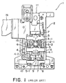
- Fig. 1 is a plan view showing the structure of a conventional optical pickup.
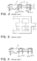
- Fig. 2 is a sectional view of the conventional actuator base shown in Fig. 1.
- Fig. 3 is a plan view showing a punched piece portion obtained by punching for manufacturing the conventional actuator base shown in Fig. 1.
- Fig. 4 is a sectional view for illustrating a modified example of the actuator base shown in Fig. 2.
- Fig. 5 is a development of an actuator base for use as a manufacturing method according to the present invention.
- Fig. 6 is a plan view of the actuator base obtained by bending the punched piece made by the punching based on the development shown in Fig. 5.
- Fig. 7 is a side view of the actuator base shown in Fig. 6.
-
- In order to facilitate understanding of the present invention, a conventional optical pickup for use as an optical disc recording/reproducing device such as a CD-R device will be described with reference to Fig. 1.
- The optical pickup 1 comprises an
optical base 2, alens holder 3, adamper base 4, and anactuator base 5. Thelens holder 3 comprises an objective lens 3-1, a tracking coil (not shown), and a focusing coil (not shown). Theactuator base 5 is used for accommodating thelens holder 3 and thedamper base 4. - The optical pickup 1 also comprises a laser unit 11 as a laser-beam source for emitting a laser beam. The surface of the optical disc (CD-R) is irradiated with the laser beam emitted from the laser unit 11 through a diffraction grating, a beam splitter, a collimating lens, and the objective lens 3-1. The optical disc is an optical storage medium. The laser beam reflected from the optical disc is launched into a photodiode (PD) through the objective lens 3-1, the collimating lens, and the beam splitter. The photodiode is a light-receiving device for receiving the laser beam reflected from the optical disc.
- The laser unit 11 and an optical system such as the beam splitter are held by the
optical base 2. In addition, theoptical base 2 is fixed to a casing (not shown) of an optical disc drive. Acircuit board 15 is fixed to one side of theoptical base 2. Thecircuit board 15 is electrically connected to other circuit elements (not shown) of the optical disc drive byflexible cables 16 connected thereto. - The
lens holder 3 is connected to thedamper base 4 via plural pieces ofsuspension wire 6. The assembly of these parts is accommodated in theactuator base 5. A portion of theactuator base 5 is ayoke 7. A permanent magnet ( to be described later) is combined with theyoke 7. - The
actuator base 5 is of an elongated-rectangular frame-shaped structure formed of a metallic and magnetic material. One side of the frame-shaped structure has a receiving portion (not shown) for thedamper base 4. This receiving portion has a supporting block 5-1 for fixing thedamper base 4. The supporting block 5-1 is unitarily formed with theactuator base 5. Approximately semi-circular protrusions 5-2 are respectively formed on both longitudinal side-walls of the frame-shaped structure. The protrusions 5-2 are supported by supporting portions 2-1 disposed in theoptical base 2. - A damper base cover 4-1 formed of a transparent resin material is fixed to the
damper base 4. In the rear portion of the damper base cover 4-1, fixing portions 4-2 each for fixing one end of pieces of thesuspension wire 6 are disposed. A space between thedamper base 4 and the damper base cover 4-1 is filled with a vibration-damping material (not shown) for damping the vibration of thesuspension wires 6. - On the rear wall of the
damper base 4, aflexible wiring board 8 for connecting to end portions of thesuspension wire 6 by soldering is disposed. Thedamper base 4 is fixed in an inserted state into a space between both side-walls of theactuator base 5 and the supporting block 5-1. - The
damper base 4 is secured by a screw (or a bolt) 9 and anut 10 so as to pinch the supporting block 5-1 and a portion of thedamper base 4. Thedamper base 4 is rotatable about thescrew 9. This is for the purpose of skewing adjustment. - Before the
damper base 4 is fixed to theactuator base 5, thesuspension wires 6 are secured to thedamper base 4. That is, thelens holder 3 and thedamper base 4 are accommodated in theactuator base 5 to be fixed thereto in a state of an assembly connected by thesuspension wires 6. - Such an optical pickup is disclosed in Japanese Patent Application No. 10-337509, for example.
- The
actuator base 5 of the optical pickup shown in Fig. 1 is in a shape shown in Figs. 2 and 3. Theactuator base 5 shown in Figs. 1 to 3 is used for driving thelens holder 3. Thelens holder 3 has the objective lens 3-1 and is coiled by the tracking coil and the focusing coil as well. Accordingly,permanent magnets 20 are assembled on both sides of theactuator base 5 in the longitudinal direction with thelens holder 3 in between, respectively. - Two inverted U-shaped portions are formed in the
actuator base 5 so as to be disposed between both of the longitudinal side-walls thereof. Eachpermanent magnet 20 is assembled to an inverted U-shaped portion. The twopermanent magnets 20 form two magnetic circuits with theactuator base 5. The inverted U-shaped portion has two plate portions extending downwardly. In the two plate portions, one disposed farther from thelens holder 3 is called a back yoke 5-11 while the other disposed closer to thelens holder 3 is called an opposing yoke 5-12. A function of such magnetic circuit is also disclosed in Japanese Unexamined Patent Publication No. 10-334485, for example. - Incidentally, in the above-mentioned
actuator base 5, a sufficient thickness is needed so that magnetic flux cannot leak from the inverted U-shaped portion. However, the objective lens 3-1 and thelens holder 3 are preferably as small as possible so as to obtain a high-degree of acceleration during driving of thelens holder 3. Therefore, it is necessary to reduce the distance between the opposing yokes 5-12 of the two magnetic circuits. If we set the sum of respective lengths of two opposing yokes 5-12 to be "2B", the sum of lengths "2B" becomes longer than the distance "A" between the two opposing yokes 5-12 shown in Fig. 2. This means that theactuator base 5 cannot be manufactured by press punching of one steel plate as shown in Fig. 3. - As a method for solving this problem it has been considered to make the shorter opposing yoke 5-12 longer and thinner, as shown in Fig.4. However, since the thickness of the opposing yoke 5-12 is reduced in this method, magnetic flux leakage occurs, so that a sufficient degree of acceleration cannot be obtained.
- As another method, the following is considered. Both magnetic circuits are made as separate parts and thereafter fixed together.
- However, this method has a disadvantage that the number of processes and parts increases compared with unitary and one-shot manufacturing.
- A manufacturing method for an actuator base will be described according to a preferred embodiment of the present invention with reference to Figs. 5 to 7. Figs. 6 and 7 are a plan view and a side view of an actuator base obtained according to the present invention, respectively. The actuator base obtained according to the present invention can be applied to the optical pickup shown in Fig. 1.
- An
actuator base 30 is formed of a magnetic and metallic plate and comprises an elongatedrectangular frame portion 31. Theactuator base 30 also comprises a pair ofyoke portions 32 disposed between longitudinal sides 31-1 opposing each other in theframe portion 31 and at the positions corresponding to both sides of the lens holder (shown in Fig. 1 as numeral 3). Eachyoke portion 32 is used to hold a permanent magnet and has an inverted U-shape. Eachyoke portion 32 exists so as to be disposed between the longitudinal sides 31-1 which are opposing each other. - The manufacturing method according to the embodiment has a feature that the
frame portion 31 and a pair ofyoke portions 32 can be unitarily or integrally formed by punching of one metallic plate. For such the purpose, the method has a feature that punching is performed based on a development in which the pair of yoke portions are distant from each other. An example of developments of theactuator base 30 is shown in Fig. 5. - In the
actuator base 30 shown in Fig. 5, two longitudinal sides 31-1 for forming theframe portion 31 are connected together by a front-end portion 31-2 in the direction opposite to the damper base (shown in Fig. 1 as numeral 4). From a portion of one of longitudinal sides 31-1 closer to the front-end portion 31-2, a block 31-3 for forming one of the pair ofyoke portions 32 is extending in the perpendicular direction. The block 31-3 comprises plate portions 31-3a, 31-3b, and 31-3c. The plate portion 31-3a forms a ceiling portion of the inverted U-shape portion. The plate portion 31-3b is to be the back yoke while the plate portion 31-3c is to be the opposing yoke. From a portion of the other of longitudinal sides 31-1 closer to the rear-end portion, a block 31-4 forming the other of the pair ofyoke portions 32 is extending in the perpendicular direction. - The block 31-4 comprises plate portions 31-4a, 31-4b, 31-4c, 31-4d, and 31-4e. The plate portion 31-4a forms a ceiling portion of the inverted U-shape portion. The plate portion 31-4b is to be the back yoke while the plate portion 31-4c is to be the opposing yoke. The plate portions 31-4d and 31-4e form an approximate U-shaped portion along with the plate portion 31-4b so as to secure a space for holding the damper base. In the plate portion 31-4d, a hole 31-41 for inserting a screw is formed. In the plate portion 31-4e, a hole 31-42 for inserting a screw is formed by drawing.
- Approximately semi-circular protrusions 31-11 corresponding to the approximately semi-circular protrusions 5-2 described in Fig. 1 are formed by drawing in the two longitudinal sides 31-1, respectively. The plate portions of the blocks 31-3 and 31-4 for forming the
yoke portions 32 have the same thickness. - Press-bending is performed on the punched piece after punching shown in Fig. 5. In Fig. 5, the portion indicated as "BENDING UPWARDLY" on a dashed line means that bending is to be performed at about 90° upwardly viewing the drawing. In this case, after bending the plate portions 31-3b and 31-3c at 90° upwardly, the plate portion 31-3a is bent at 90° upwardly. On the other hand, the plate portion 31-4d is bent at 90° downwardly relative to the plate portion 31-4b and further the plate portion 31-4e is bent at 90° downwardly relative to the plate portion 31-4d. Then after bending of the plate portions 31-4b and 31-4c at 90° upwardly, the plate portion 31-4a is bent at 90° upwardly. Furthermore, the portions of two longitudinal sides 31-1 at the both ends of the front-end portion 31-2 are respectively bent at 90° upwardly. Consequently, the shape shown in Fig. 6 can be obtained. The portions butting each other in consequence of the above-mentioned bending may be preferably reinforced by adhesion or staking. Such the portions are indicated as "ADHESION OR STAKING" in Figs. 5 to 7.
- As understood by the above description, in the manufacturing method according to the present invention, blocks for forming a pair of yoke portions can be punched based on a development in which these blocks are distant from each other. Consequently, even when the pair of yoke portions are located close to each other after bending, the actuator base can be manufactured without reducing the thickness of the opposing yoke. Thereby magnetic flux leakage can be eliminated and a high-degree of acceleration can be obtained during driving of the lens holder.
- While the present invention has been described in its preferred embodiments, it is to be understood that the words which have been used are words of description rather than limitation, and that changes may be made to the invention without departing from its scope as defined by the appended claims.
- Each feature disclosed in this specification (which term includes the claims) and/or shown in the drawings may be incorporated in the invention independently of other disclosed and/or illustrated features.
- The text of the abstract filed herewith is repeated here as part of the specification.
- An actuator base comprises an elongated rectangular frame portion. In the actuator base, a pair of yoke portions are formed to exit between longitudinal sides of the frame portion opposing each other. The forming of the actuator base is performed by punching the frame portion and the pair of yoke portions unitarily from one metallic plate. The punching is performed based on a development in which the pair of yoke portions are distant from each other in advance.
Claims (5)
- A method for manufacturing an actuator base for an optical pickup, the actuator base being formed of a magnetic and metallic material and comprising an inverted U-shaped pair of yoke portions for holding permanent magnets at positions corresponding to both sides of a lens holder of the optical pickup, said method comprising:punching a frame portion and a pair of yoke portions unitarily from a metallic plate, whereby to provide an elongated rectangular frame portion as the actuator base, the pair of yoke portions being disposed between longitudinal sides of the frame portion and opposing each other in the frame portion;
wherein said step of punching the frame portion and the pair of yoke portions is performed based on a development in which the pair of yoke portions are remote from each other. - A method according to claim 1, wherein said step of punching the frame portion and the pair of yoke portions comprises equalizing the thickness of the inverted U-shaped portions in the pair of yoke portions.
- A metallic plate punched to form unitarily a frame portion and a pair of yoke portions of an optical base for an optical pickup, the metallic plate after punching and before bending into usable form having two parallel frame segments connected by a connecting segment, a yoke segment extending from each frame segment in a direction generally normal to the respective frame segment, the two yoke segments extending in opposite directions from each other, each yoke segment having an arm extending generally normal to the frame segments, each arm having a pair of flaps, each flap extending from an opposite side of the arm;
wherein the metallic plate is configured by the punching such that when the metallic plate is bent into usable form, with a portion of the arms of the two yoke segments being brought into a coplanar relation, the distance between the arms of the two yoke segments is less than the aggregate length of their adjacent respective flaps. - A metallic plate as in claim 3, wherein portions of the plate forming the two yoke segments have the same thickness.
- A method for manufacturing an actuator base for an optical pickup, the the method comprising the steps of:punching the metallic plate of claim 3 or 4; and,bending the metallic plate into the usable form.
Applications Claiming Priority (2)
| Application Number | Priority Date | Filing Date | Title |
|---|---|---|---|
| JP1980699 | 1999-01-28 | ||
| JP11019806A JP2000215481A (en) | 1999-01-28 | 1999-01-28 | Method of manufacturing actuator base for optical pickup |
Publications (1)
| Publication Number | Publication Date |
|---|---|
| EP1024482A1 true EP1024482A1 (en) | 2000-08-02 |
Family
ID=12009587
Family Applications (1)
| Application Number | Title | Priority Date | Filing Date |
|---|---|---|---|
| EP00300682A Withdrawn EP1024482A1 (en) | 1999-01-28 | 2000-01-28 | Actuator base for optical pickup and method for manufacturing the same |
Country Status (2)
| Country | Link |
|---|---|
| EP (1) | EP1024482A1 (en) |
| JP (1) | JP2000215481A (en) |
Cited By (2)
| Publication number | Priority date | Publication date | Assignee | Title |
|---|---|---|---|---|
| US6999658B2 (en) | 2002-06-28 | 2006-02-14 | California Institute Of Technology | Optical resonator and laser applications |
| US7027476B2 (en) | 2002-08-09 | 2006-04-11 | California Institute Of Technology | Tunable semiconductor lasers |
Citations (5)
| Publication number | Priority date | Publication date | Assignee | Title |
|---|---|---|---|---|
| JPH0323023A (en) * | 1989-06-20 | 1991-01-31 | Sankoo:Kk | Assembly parts manufacturing method and assembly parts |
| EP0419097A2 (en) * | 1989-09-18 | 1991-03-27 | Sony Corporation | Objective lens driving devices |
| EP0525742A2 (en) * | 1991-07-29 | 1993-02-03 | Sony Corporation | Objective lens moving actuator |
| US5303089A (en) * | 1992-06-03 | 1994-04-12 | Ricoh Company, Ltd. | Objective lens drive unit |
| US5687030A (en) * | 1994-08-25 | 1997-11-11 | Sony Corporation | Biaxial actuator |
-
1999
- 1999-01-28 JP JP11019806A patent/JP2000215481A/en not_active Withdrawn
-
2000
- 2000-01-28 EP EP00300682A patent/EP1024482A1/en not_active Withdrawn
Patent Citations (5)
| Publication number | Priority date | Publication date | Assignee | Title |
|---|---|---|---|---|
| JPH0323023A (en) * | 1989-06-20 | 1991-01-31 | Sankoo:Kk | Assembly parts manufacturing method and assembly parts |
| EP0419097A2 (en) * | 1989-09-18 | 1991-03-27 | Sony Corporation | Objective lens driving devices |
| EP0525742A2 (en) * | 1991-07-29 | 1993-02-03 | Sony Corporation | Objective lens moving actuator |
| US5303089A (en) * | 1992-06-03 | 1994-04-12 | Ricoh Company, Ltd. | Objective lens drive unit |
| US5687030A (en) * | 1994-08-25 | 1997-11-11 | Sony Corporation | Biaxial actuator |
Non-Patent Citations (1)
| Title |
|---|
| PATENT ABSTRACTS OF JAPAN vol. 015, no. 142 (M - 1101) 10 April 1991 (1991-04-10) * |
Cited By (2)
| Publication number | Priority date | Publication date | Assignee | Title |
|---|---|---|---|---|
| US6999658B2 (en) | 2002-06-28 | 2006-02-14 | California Institute Of Technology | Optical resonator and laser applications |
| US7027476B2 (en) | 2002-08-09 | 2006-04-11 | California Institute Of Technology | Tunable semiconductor lasers |
Also Published As
| Publication number | Publication date |
|---|---|
| JP2000215481A (en) | 2000-08-04 |
Similar Documents
| Publication | Publication Date | Title |
|---|---|---|
| JP4448736B2 (en) | Optical pickup device and optical disk device using the same | |
| JP2001344780A (en) | Optical drive device and optical storage device | |
| US8220012B2 (en) | Holding member, driving apparatus, pickup apparatus, and disc apparatus | |
| US7522358B2 (en) | Optical head device and manufacturing method therefor | |
| JP2000252577A (en) | Laser beam emission unit | |
| US20130003520A1 (en) | Objective lens driving apparatus | |
| JP4088326B2 (en) | Optical pickup device | |
| JP2000215481A (en) | Method of manufacturing actuator base for optical pickup | |
| CN1355918A (en) | Optical pick-up apparatus | |
| US8938746B2 (en) | Object lens driving device and optical disc drive including the same | |
| EP1696427B1 (en) | Fitting structure for fitting laser holder to base member | |
| JP4509854B2 (en) | Objective lens driving device, optical pickup device and optical disk device | |
| JP4491324B2 (en) | Optical pickup | |
| JP3639132B2 (en) | Optical pickup | |
| KR100624850B1 (en) | Optical pickup | |
| EP1193698A2 (en) | Laser diode fixing method | |
| EP1005029A1 (en) | Optical pickup comprising a damper base having an oval hole | |
| JPH10289455A (en) | Objective lens driving device and its production | |
| JPH05342606A (en) | Objective lens drive | |
| JP2004296039A (en) | Optical pickup device | |
| JPH1186312A (en) | Optical pickup | |
| JP4350666B2 (en) | Objective lens driving device, optical pickup device and optical disk device | |
| JP2007058900A (en) | Optical head | |
| JP2000057611A (en) | Optical pickup device | |
| JP2004178626A (en) | Optical pickup |
Legal Events
| Date | Code | Title | Description |
|---|---|---|---|
| PUAI | Public reference made under article 153(3) epc to a published international application that has entered the european phase |
Free format text: ORIGINAL CODE: 0009012 |
|
| AK | Designated contracting states |
Kind code of ref document: A1 Designated state(s): DE FR GB NL |
|
| AX | Request for extension of the european patent |
Free format text: AL;LT;LV;MK;RO;SI |
|
| 17P | Request for examination filed |
Effective date: 20001215 |
|
| AKX | Designation fees paid |
Free format text: DE FR GB NL |
|
| STAA | Information on the status of an ep patent application or granted ep patent |
Free format text: STATUS: THE APPLICATION IS DEEMED TO BE WITHDRAWN |
|
| 18D | Application deemed to be withdrawn |
Effective date: 20030801 |