EP1024291A2 - Multistage pump for supplying semi-solid material - Google Patents
Multistage pump for supplying semi-solid material Download PDFInfo
- Publication number
- EP1024291A2 EP1024291A2 EP00200272A EP00200272A EP1024291A2 EP 1024291 A2 EP1024291 A2 EP 1024291A2 EP 00200272 A EP00200272 A EP 00200272A EP 00200272 A EP00200272 A EP 00200272A EP 1024291 A2 EP1024291 A2 EP 1024291A2
- Authority
- EP
- European Patent Office
- Prior art keywords
- impeller
- pump
- feeder screw
- impellers
- chamber
- Prior art date
- Legal status (The legal status is an assumption and is not a legal conclusion. Google has not performed a legal analysis and makes no representation as to the accuracy of the status listed.)
- Withdrawn
Links
Images


Classifications
-
- F—MECHANICAL ENGINEERING; LIGHTING; HEATING; WEAPONS; BLASTING
- F04—POSITIVE - DISPLACEMENT MACHINES FOR LIQUIDS; PUMPS FOR LIQUIDS OR ELASTIC FLUIDS
- F04D—NON-POSITIVE-DISPLACEMENT PUMPS
- F04D1/00—Radial-flow pumps, e.g. centrifugal pumps; Helico-centrifugal pumps
- F04D1/06—Multi-stage pumps
-
- F—MECHANICAL ENGINEERING; LIGHTING; HEATING; WEAPONS; BLASTING
- F04—POSITIVE - DISPLACEMENT MACHINES FOR LIQUIDS; PUMPS FOR LIQUIDS OR ELASTIC FLUIDS
- F04D—NON-POSITIVE-DISPLACEMENT PUMPS
- F04D7/00—Pumps adapted for handling specific fluids, e.g. by selection of specific materials for pumps or pump parts
- F04D7/02—Pumps adapted for handling specific fluids, e.g. by selection of specific materials for pumps or pump parts of centrifugal type
- F04D7/04—Pumps adapted for handling specific fluids, e.g. by selection of specific materials for pumps or pump parts of centrifugal type the fluids being viscous or non-homogenous
Definitions
- the present invention relates to a pump intended to supply composite materials, namely materials wherein solid bodies are dispersed in a liquid so as to form a non-homogeneous composition, which in the remainder of this description and in the claims that follow will be referred to in short as "semi-solid material".
- An example of such materials is that formed by the must and the grapes pressed during the course of the wine production process.
- the must together with the pressed grapes is poured from above into a hopper which has, at the bottom, a feeder screw that pushes the composite material into a chamber where an impeller is situated; the latter is mounted on the same shaft as the feeder screw and has a particular biconvex shape.
- the material to be pumped reaches the impeller, advancing in an axial direction with respect thereto and is then pushed radially, after rotation through about 270°, towards a delivery header located on the upper cover of the casing inside which the impeller is housed.
- a delivery header located on the upper cover of the casing inside which the impeller is housed.
- an air tank intended to absorb the pressure oscillations in the pump delivery.
- the said pump has the advantage that it is compact and efficient because the feeder screw and the impeller are keyed onto the same shaft so that it may be favourably used in numerous practical applications.
- the object of the present invention is that of improving this situation; said object is achieved by a pump, whose characterising features are set out in the claims appended to this description.
- the pump of this of embodiment is denoted in its entirety by 1; it comprises the usual hopper 2 with associated feeder screw 3 for supplying the material into a casing 4, which is closed at the top by a cover 5 and which has internally two impellers 6 and 7 of the type already described in the abovementioned utility model, namely having a biconvex shape.
- a partition 9 is arranged between the two impellers 6 and 7 and divides the inside of the casing 4 into two chambers 10 and 11, which have a substantially cylindrical shape and inside which the two impellers 6 and 7 are respectively housed; the two aforementioned chambers communicate with each other in the upper zone where there is a through-opening 12 between the partition 9 and the cover 5 of the casing.
- a tank 13 which is known per se and fixed to the cover 5 is located above the chamber 10, while a delivery header 14 of the pump is arranged above the chamber 11; the said header is oriented so as to assist the action of the impellers produced by the direction of their rotation.
- the header is substantially aligned with the direction of the speed of the outflowing semi-solid material, pushed by the impellers at the end of the rotation through about 270°, as mentioned above.
- each of the impellers 6 and 7 has respectively associated with it movable flaps 15 and 16 pivoting about a common hinging pin 17 and having an edge kept in contact with the surface of the impellers by means of a spring 18 which exerts elastically a torque on this pin.
- the inside of the casing 4 and the hopper 2 are connected by a duct inside which the downstream end of the feeder screw 3 is located; the duct 20 contains a baffle plate 21 which is configured substantially in the form of a half-moon and which defines, together with the internal wall of the said duct, an opening 22 for allowing the material supplied by the feeder screw to pass through.
- the partition 9 which divides the two chambers 10 and 11 is also configured in a manner similar to that of the baffle plate 21 in the sense that it is also shaped so as to define with the internal wall of the casing 4 a second opening 23 for allowing the material to pass from the first chamber to the second chamber.
- the pump is completed by a gearmotor 25 which performs rotation of the shaft 8 and a series of wheels 26 that facilitate movement of the pump which, for this purpose, is also provided with an arm 27 acting as a handle.
- the normal operating mode i.e. excluding the initial or final transients of the pump described hitherto, takes place as follows.
- the must and the marc which is situated inside the hopper 2 is fed forwards by the feeder screw 3 towards the duct 20 and from here, passing through the opening 22 in the baffle plate 21, enters into the first chamber 10.
- each impeller As mentioned, the material taken up by each impeller is pushed upwards inside the respective chamber 10 and 11; from the first of these chambers it is also sucked, across the through-opening 12, into the second chamber so as to emerge, together with the material processed by the impeller 7, from the header 14.
- the tank 13 acts as a compensator for the (sinusoidal-type) pressure oscillations which occur inside the casing 4 as a result of the action of each impeller; in this connection it should be pointed out that, even though some marc may fill the bottom part of the tank, the latter essentially acts as a storage chamber which communicates with the chamber 10 and inside which the stored air may be compressed or expanded according to the circumstances.
- the pump according to the present invention demonstrated an excellent efficiency; indeed it retained the same advantages of compactness and simplicity associated with the version described in the prior utility model (there is only a slight axial elongation due to the second impeller), while achieving, however, a surprisingly favourable performance.
Landscapes
- Engineering & Computer Science (AREA)
- Mechanical Engineering (AREA)
- General Engineering & Computer Science (AREA)
- Structures Of Non-Positive Displacement Pumps (AREA)
- Compressors, Vaccum Pumps And Other Relevant Systems (AREA)
- Static Random-Access Memory (AREA)
- Liquid Deposition Of Substances Of Which Semiconductor Devices Are Composed (AREA)
Abstract
Description
- The present invention relates to a pump intended to supply composite materials, namely materials wherein solid bodies are dispersed in a liquid so as to form a non-homogeneous composition, which in the remainder of this description and in the claims that follow will be referred to in short as "semi-solid material".
- An example of such materials is that formed by the must and the grapes pressed during the course of the wine production process.
- Indeed, during this process it is known that the pressed grape is left to macerate in its own must; this is performed in particular during the production of red wines in order to provide the must with the desired colouring, owing to the substances which are released therein by the skins of the macerated grapes.
- Consequently the need arises to transfer the semi-solid material formed by the must and the skins present therein, from the pressing machine into special tanks intended for maceration; this operation is performed with the aid of special pumps to which this invention relates.
- Italian Utility Model No. 229,226, which belongs to the same Applicants of the present application, discloses a pump for semi-solid materials which may be briefly described as follows.
- The must together with the pressed grapes is poured from above into a hopper which has, at the bottom, a feeder screw that pushes the composite material into a chamber where an impeller is situated; the latter is mounted on the same shaft as the feeder screw and has a particular biconvex shape.
- The material to be pumped reaches the impeller, advancing in an axial direction with respect thereto and is then pushed radially, after rotation through about 270°, towards a delivery header located on the upper cover of the casing inside which the impeller is housed. In some cases it is also known to provide on this cover an air tank intended to absorb the pressure oscillations in the pump delivery.
- The said pump has the advantage that it is compact and efficient because the feeder screw and the impeller are keyed onto the same shaft so that it may be favourably used in numerous practical applications.
- In order to increase the performance of this machine, however, the need has arisen to improve the operation thereof.
- In particular it was found that an increase in the flowrate at the output beyond certain values resulted in a loss of efficiency and therefore an unsatisfactory energy consumption, while keeping all other conditions unchanged.
- The object of the present invention is that of improving this situation; said object is achieved by a pump, whose characterising features are set out in the claims appended to this description.
- A non-limiting and exemplary embodiment of the invention will be now described and illustrated in the accompanying drawings, wherein:
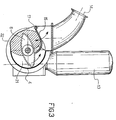
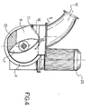
- Fig. 1 shows a perspective view of the aforementioned example of embodiment of the pump;
- Fig. 2 shows a cross-sectional view along the line II-II of the preceding figure;
- Figures 3 and 4 are respective cross-sectional views along the lines III-III and IV-IV of Fig. 2.
- The pump of this of embodiment is denoted in its entirety by 1; it comprises the
usual hopper 2 with associatedfeeder screw 3 for supplying the material into acasing 4, which is closed at the top by acover 5 and which has internally twoimpellers - These impellers are keyed onto the
same shaft 8 of thefeeder screw 3 in a manner staggered at 90° with respect to each other (see Fig. 2), so that when following the rotation of theshaft 8 one is arranged vertically, the other one instead is directed horizontally. - A partition 9 is arranged between the two
impellers casing 4 into twochambers 10 and 11, which have a substantially cylindrical shape and inside which the twoimpellers cover 5 of the casing. - A
tank 13 which is known per se and fixed to thecover 5 is located above thechamber 10, while adelivery header 14 of the pump is arranged above the chamber 11; the said header is oriented so as to assist the action of the impellers produced by the direction of their rotation. In other words, the header is substantially aligned with the direction of the speed of the outflowing semi-solid material, pushed by the impellers at the end of the rotation through about 270°, as mentioned above. - Moreover, each of the
impellers movable flaps pin 17 and having an edge kept in contact with the surface of the impellers by means of aspring 18 which exerts elastically a torque on this pin. - The inside of the
casing 4 and thehopper 2 are connected by a duct inside which the downstream end of thefeeder screw 3 is located; theduct 20 contains abaffle plate 21 which is configured substantially in the form of a half-moon and which defines, together with the internal wall of the said duct, anopening 22 for allowing the material supplied by the feeder screw to pass through. - The partition 9 which divides the two
chambers 10 and 11 is also configured in a manner similar to that of thebaffle plate 21 in the sense that it is also shaped so as to define with the internal wall of the casing 4 asecond opening 23 for allowing the material to pass from the first chamber to the second chamber. - Finally, the pump is completed by a
gearmotor 25 which performs rotation of theshaft 8 and a series ofwheels 26 that facilitate movement of the pump which, for this purpose, is also provided with anarm 27 acting as a handle. - The normal operating mode (i.e. excluding the initial or final transients) of the pump described hitherto, takes place as follows.
- The must and the marc which is situated inside the
hopper 2 is fed forwards by thefeeder screw 3 towards theduct 20 and from here, passing through the opening 22 in thebaffle plate 21, enters into thefirst chamber 10. - Here a fraction of the throughput supplied by the feeder screw is taken up by the
first impeller 6 which pushes it from the bottom part of thechamber 10 towards the top part thereof. - In the meantime another fraction of the throughput supplied by the feeder screw enters into the second chamber 11, passing through the opening 23 in the dividing partition 9; this fraction is taken up by the
second impeller 7 with a predefined delay with respect to the first impeller, due to the 90° staggered arrangement with which they are keyed onto thedrive shaft 8. - As mentioned, the material taken up by each impeller is pushed upwards inside the
respective chamber 10 and 11; from the first of these chambers it is also sucked, across the through-opening 12, into the second chamber so as to emerge, together with the material processed by theimpeller 7, from theheader 14. - During operation of the pump, the
tank 13 acts as a compensator for the (sinusoidal-type) pressure oscillations which occur inside thecasing 4 as a result of the action of each impeller; in this connection it should be pointed out that, even though some marc may fill the bottom part of the tank, the latter essentially acts as a storage chamber which communicates with thechamber 10 and inside which the stored air may be compressed or expanded according to the circumstances. - The pump according to the present invention demonstrated an excellent efficiency; indeed it retained the same advantages of compactness and simplicity associated with the version described in the prior utility model (there is only a slight axial elongation due to the second impeller), while achieving, however, a surprisingly favourable performance.
- In other words, for the same capacity of the
casing 4, the use of two impellers according to the teaching of the present invention, instead of a single impeller, results in a pump for semi-solid materials with a lower consumption and an improved efficiency. - In addition, the staggering of the action of the two impellers due to their keyed arrangement staggered at 90° reduces the amplitude of the pressure oscillations inside the pump and also at its delivery.
Claims (6)
- Pump for supplying semi-solid material, comprising a hopper (2), a feeder screw (3) arranged inside this hopper, a first biconvex impeller (6) mounted downstream of the feeder screw on the same shaft (8) as the latter and housed inside a corresponding chamber (10) into which the feeder screw pushes the material contained in the hopper, characterized in that it comprises a second biconvex impeller (7) mounted downstream of the first impeller on the same shaft as the latter and housed inside an associated chamber (11) communicating with the other chamber, respectively, at the top so as to allow material taken up by the first impeller to pass through and at the bottom so as to allow feeding inside it of the material pushed by the feeder screw.
- Pump according to Claim 1, wherein the impellers (6, 7) are mounted staggered with respect to each other.
- Pump according to Claim 2, wherein the staggering between the impellers (6, 7) is equal to 90°.
- Pump according to Claims 1 to 3, wherein the chambers (10, 11) housing the impellers (6, 7) are separated by a partition (9) which is transverse with respect to a casing (4) and which defines at the top, together with an upper cover (5) closing this casing, an opening (12) for communication between the two chambers.
- Pump according to Claim 4, wherein the partition (9) is shaped so as to define at the bottom, together with the internal wall of the casing (4), an opening (23) for allowing the material supplied by the feeder screw (3) to pass through.
- Pump according to any one of the preceding claims, comprising a tank (13) for damping the pressure oscillations, arranged opposite the first impeller (6), above the latter, and a delivery header (14) arranged opposite the second impeller (7), above the latter.
Applications Claiming Priority (2)
| Application Number | Priority Date | Filing Date | Title |
|---|---|---|---|
| IT1999TV000005U IT248089Y1 (en) | 1999-01-29 | 1999-01-29 | MULTI-STAGE PUMP FOR THE SUPPLY OF SEMI-SOLID MATERIAL. |
| ITTV990005U | 1999-01-29 |
Publications (2)
| Publication Number | Publication Date |
|---|---|
| EP1024291A2 true EP1024291A2 (en) | 2000-08-02 |
| EP1024291A3 EP1024291A3 (en) | 2000-11-08 |
Family
ID=11420532
Family Applications (1)
| Application Number | Title | Priority Date | Filing Date |
|---|---|---|---|
| EP00200272A Withdrawn EP1024291A3 (en) | 1999-01-29 | 2000-01-26 | Multistage pump for supplying semi-solid material |
Country Status (2)
| Country | Link |
|---|---|
| EP (1) | EP1024291A3 (en) |
| IT (1) | IT248089Y1 (en) |
Cited By (2)
| Publication number | Priority date | Publication date | Assignee | Title |
|---|---|---|---|---|
| RU2188968C1 (en) * | 2001-04-26 | 2002-09-10 | Бритвин Лев Николаевич | Feed system of high-viscosity materials |
| CN111608918A (en) * | 2020-05-28 | 2020-09-01 | 陕西省环境保护公司 | Sludge pump anti-clogging device in methanol sewage treatment |
Families Citing this family (1)
| Publication number | Priority date | Publication date | Assignee | Title |
|---|---|---|---|---|
| IT1311627B1 (en) | 1999-01-18 | 2002-03-14 | Benetton Spa | SUPPORT STRUCTURE, PARTICULARLY FOR FOOTWEAR. |
Family Cites Families (3)
| Publication number | Priority date | Publication date | Assignee | Title |
|---|---|---|---|---|
| US2042641A (en) * | 1934-11-13 | 1936-06-02 | Frank F Victoria | Pulp and liquid pump |
| US4141510A (en) * | 1977-06-15 | 1979-02-27 | Arthur Smith | Material reduction means for pumps |
| IT229226Y1 (en) * | 1992-03-12 | 1998-07-02 | Velo Spa | EQUIPMENT FOR THE TRANSFER OF SEMI-SOLID PRODUCTS SUCH AS, FOR EXAMPLE, IN PARTICULAR VINACCE MUST AND SIMILAR |
-
1999
- 1999-01-29 IT IT1999TV000005U patent/IT248089Y1/en active
-
2000
- 2000-01-26 EP EP00200272A patent/EP1024291A3/en not_active Withdrawn
Cited By (2)
| Publication number | Priority date | Publication date | Assignee | Title |
|---|---|---|---|---|
| RU2188968C1 (en) * | 2001-04-26 | 2002-09-10 | Бритвин Лев Николаевич | Feed system of high-viscosity materials |
| CN111608918A (en) * | 2020-05-28 | 2020-09-01 | 陕西省环境保护公司 | Sludge pump anti-clogging device in methanol sewage treatment |
Also Published As
| Publication number | Publication date |
|---|---|
| ITTV990005U1 (en) | 2000-07-29 |
| IT248089Y1 (en) | 2002-12-10 |
| EP1024291A3 (en) | 2000-11-08 |
Similar Documents
| Publication | Publication Date | Title |
|---|---|---|
| EP3708350B1 (en) | Extrusion separation and purification device | |
| CN206552868U (en) | A kind of silty material delivers machine | |
| EP1024291A2 (en) | Multistage pump for supplying semi-solid material | |
| CN207738625U (en) | A kind of sludge dehydration device | |
| AU1131501A (en) | A tank and a centrifugal pump for emptying the tank | |
| CN207630307U (en) | A kind of high efficiency mixer | |
| CN201246270Y (en) | Hydraulic motor | |
| CN115161160A (en) | Simulation intestinal canal type high-solid anaerobic digestion reactor with real-time solid-liquid separation function | |
| CN213886160U (en) | Stirrer for reaction kettle | |
| CN207630413U (en) | A kind of elastic helix rotor mold | |
| CN209076814U (en) | A kind of instant nut food horizontal ball mill | |
| CN218393927U (en) | Grinding head group of vacuum grinding pump and vacuum grinding pump | |
| CN215549761U (en) | Dry and wet material adding and mixing device | |
| CN212441497U (en) | Ball mill for processing autoclaved aerated concrete products | |
| CN211636092U (en) | Feed mixer capable of uniformly spraying liquid | |
| CN211246759U (en) | Impact crusher with flywheel | |
| CN222343063U (en) | Multistage milling equipment | |
| CN207375209U (en) | A kind of green manure tumbler cylinder | |
| CN221032974U (en) | Piston pump annotates material device | |
| CN208594190U (en) | A kind of Moisture separation device of paper mill sludge | |
| CN101629567B (en) | Gas-liquid mixing pump | |
| CN220489860U (en) | Extrusion mechanism of electro-optical flower manufacturing equipment | |
| CN218931815U (en) | Pressure algae filtering drainage device | |
| CN206972509U (en) | A kind of screw pump | |
| CN216106826U (en) | Oil press with rapeseed pre-cleaning function |
Legal Events
| Date | Code | Title | Description |
|---|---|---|---|
| PUAI | Public reference made under article 153(3) epc to a published international application that has entered the european phase |
Free format text: ORIGINAL CODE: 0009012 |
|
| AK | Designated contracting states |
Kind code of ref document: A2 Designated state(s): DE ES FR GR IT PT |
|
| AX | Request for extension of the european patent |
Free format text: AL;LT;LV;MK;RO;SI |
|
| PUAL | Search report despatched |
Free format text: ORIGINAL CODE: 0009013 |
|
| AK | Designated contracting states |
Kind code of ref document: A3 Designated state(s): AT BE CH CY DE DK ES FI FR GB GR IE IT LI LU MC NL PT SE |
|
| AX | Request for extension of the european patent |
Free format text: AL;LT;LV;MK;RO;SI |
|
| 17P | Request for examination filed |
Effective date: 20010312 |
|
| AKX | Designation fees paid |
Free format text: DE ES FR GR IT PT |
|
| STAA | Information on the status of an ep patent application or granted ep patent |
Free format text: STATUS: THE APPLICATION IS DEEMED TO BE WITHDRAWN |
|
| 18D | Application deemed to be withdrawn |
Effective date: 20030801 |