EP1024282A2 - Control method and apparatus for variable discharge-type high pressure pumps - Google Patents
Control method and apparatus for variable discharge-type high pressure pumps Download PDFInfo
- Publication number
- EP1024282A2 EP1024282A2 EP00100854A EP00100854A EP1024282A2 EP 1024282 A2 EP1024282 A2 EP 1024282A2 EP 00100854 A EP00100854 A EP 00100854A EP 00100854 A EP00100854 A EP 00100854A EP 1024282 A2 EP1024282 A2 EP 1024282A2
- Authority
- EP
- European Patent Office
- Prior art keywords
- pressure
- fuel
- chamber
- control
- valve
- Prior art date
- Legal status (The legal status is an assumption and is not a legal conclusion. Google has not performed a legal analysis and makes no representation as to the accuracy of the status listed.)
- Granted
Links
Images


Classifications
-
- F—MECHANICAL ENGINEERING; LIGHTING; HEATING; WEAPONS; BLASTING
- F02—COMBUSTION ENGINES; HOT-GAS OR COMBUSTION-PRODUCT ENGINE PLANTS
- F02M—SUPPLYING COMBUSTION ENGINES IN GENERAL WITH COMBUSTIBLE MIXTURES OR CONSTITUENTS THEREOF
- F02M63/00—Other fuel-injection apparatus having pertinent characteristics not provided for in groups F02M39/00 - F02M57/00 or F02M67/00; Details, component parts, or accessories of fuel-injection apparatus, not provided for in, or of interest apart from, the apparatus of groups F02M39/00 - F02M61/00 or F02M67/00; Combination of fuel pump with other devices, e.g. lubricating oil pump
- F02M63/02—Fuel-injection apparatus having several injectors fed by a common pumping element, or having several pumping elements feeding a common injector; Fuel-injection apparatus having provisions for cutting-out pumps, pumping elements, or injectors; Fuel-injection apparatus having provisions for variably interconnecting pumping elements and injectors alternatively
- F02M63/0225—Fuel-injection apparatus having a common rail feeding several injectors ; Means for varying pressure in common rails; Pumps feeding common rails
-
- F—MECHANICAL ENGINEERING; LIGHTING; HEATING; WEAPONS; BLASTING
- F02—COMBUSTION ENGINES; HOT-GAS OR COMBUSTION-PRODUCT ENGINE PLANTS
- F02M—SUPPLYING COMBUSTION ENGINES IN GENERAL WITH COMBUSTIBLE MIXTURES OR CONSTITUENTS THEREOF
- F02M39/00—Arrangements of fuel-injection apparatus with respect to engines; Pump drives adapted to such arrangements
- F02M39/02—Arrangements of fuel-injection apparatus to facilitate the driving of pumps; Arrangements of fuel-injection pumps; Pump drives
-
- F—MECHANICAL ENGINEERING; LIGHTING; HEATING; WEAPONS; BLASTING
- F02—COMBUSTION ENGINES; HOT-GAS OR COMBUSTION-PRODUCT ENGINE PLANTS
- F02M—SUPPLYING COMBUSTION ENGINES IN GENERAL WITH COMBUSTIBLE MIXTURES OR CONSTITUENTS THEREOF
- F02M41/00—Fuel-injection apparatus with two or more injectors fed from a common pressure-source sequentially by means of a distributor
- F02M41/08—Fuel-injection apparatus with two or more injectors fed from a common pressure-source sequentially by means of a distributor the distributor and pumping elements being combined
- F02M41/14—Fuel-injection apparatus with two or more injectors fed from a common pressure-source sequentially by means of a distributor the distributor and pumping elements being combined rotary distributor supporting pump pistons
- F02M41/1405—Fuel-injection apparatus with two or more injectors fed from a common pressure-source sequentially by means of a distributor the distributor and pumping elements being combined rotary distributor supporting pump pistons pistons being disposed radially with respect to rotation axis
- F02M41/1411—Fuel-injection apparatus with two or more injectors fed from a common pressure-source sequentially by means of a distributor the distributor and pumping elements being combined rotary distributor supporting pump pistons pistons being disposed radially with respect to rotation axis characterised by means for varying fuel delivery or injection timing
- F02M41/1427—Arrangements for metering fuel admitted to pumping chambers, e.g. by shuttles or by throttle-valves
-
- F—MECHANICAL ENGINEERING; LIGHTING; HEATING; WEAPONS; BLASTING
- F02—COMBUSTION ENGINES; HOT-GAS OR COMBUSTION-PRODUCT ENGINE PLANTS
- F02M—SUPPLYING COMBUSTION ENGINES IN GENERAL WITH COMBUSTIBLE MIXTURES OR CONSTITUENTS THEREOF
- F02M59/00—Pumps specially adapted for fuel-injection and not provided for in groups F02M39/00 -F02M57/00, e.g. rotary cylinder-block type of pumps
- F02M59/20—Varying fuel delivery in quantity or timing
- F02M59/36—Varying fuel delivery in quantity or timing by variably-timed valves controlling fuel passages to pumping elements or overflow passages
- F02M59/366—Valves being actuated electrically
Definitions
- a common rail-type fuel injection system is known as one of systems which inject fuel into diesel engines.
- a common accumulation chamber (common rail) communicating with each engine cylinder is provided.
- the fuel pressure in the accumulation chamber is maintained at a predetermined pressure by pressure-feeding of fuel the necessary amount of high pressure fuel from a variable discharge-type high pressure pump to the accumulation chamber.
- the high pressure fuel in the accumulation chamber is injected into the combustion chamber of each cylinder from an electromagnetically-operated injector at a predetermined injection timing.
- the variable discharge-type high pressure pump has a pressure chamber which is connected to the common rail and increases/decreases its displacement or volume. The amount of fuel sucked into the pressure chamber is adjusted by opening and closing of a control valve provided between the pressure chamber and a low pressure pump which feeds low pressure fuel.
- a pre-stroke type is generally used to produce the desired feed amount to the common rail by closing the control valve at a predetermined timing when the displacement of the pressure chamber is decreased to set the amount of fuel in the pressure chamber.
- the control valve is required to operate with high accuracy under high pressure condition because high pressure of fuel is applied to the control valve. The system becomes large and cost increases, if a sufficient pressure-feed amount control characteristics is required.
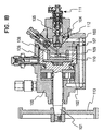
- a variable discharge-type high pressure pump is proposed as shown in Fig. 18 to solve this problem.
- a drive shaft 101 is extended through and held in a pump housing 100.
- the low pressure fuel is fed into a fuel reservoir 105 from a low pressure pump (feed pump) 102 which rotates with the drive shaft 101 through low pressure fuel passages 103 and 104.
- An inner cam 106 is formed integrally with the right end part of the drive shaft 101.
- the left end part of a head 107 is press-inserted into the inner cam 106.
- Four cylinders 108 (only two are shown in the figure) are formed in radial directions in the left end part of the head 107.
- a plunger 109 is disposed reciprocally in each cylinder 108.
- a pressure chamber 110 is defined by the radial inside end surface of the plunger 109 and the inside wall of the cylinder 108, so that fuel introduced therein may be pressurized by reciprocal movement of the plunger 109.
- a control valve 111 and a suction valve 112 are disposed from the upstream side in the flow passage extending from the fuel reservoir 105 to the pressure chamber 110.
- the control valve 111 is an electromagnetic valve the power-on or energization of which is controlled by an electronic control unit not shown.
- the suction valve 112 is a check valve which allows fuel to flow in the forward direction, that is, from the control valve 111 to the pressure chamber 110.
- the suction valve 112 opens when the pressure in the pressure chamber 110 decreases in response to opening of the control valve 111 and increase of the displacement of the pressure chamber 110 due to rearward movement of the plunger 109. It closes when the control valve 111 closes.
- the flow passage to the pressure chamber 110 is closed by the suction valve 112 from the start of pressurizing the low pressure fuel to the end of pressure-feeding of fuel, after preliminarily supplying the required amount of fuel from the feed pump 102 to the pressure chamber 110 in accordance with the valve opening period of the control valve 111.
- the pressure applied to the control valve 111 is limited at a maximum to the feed pressure (about 15 atms). Therefore, the control valve 111 need not be the type which operates with high accuracy under high pressure conditions, so that a sufficient common rail pressure control may be attained in low cost.
- a valve opening period command value of the control valve 111 is determined in accordance with a fuel injection amount which is the discharge amount of high pressure fuel from the common rail and the control valve 111 is opened and closed in response to the command value to refill the common rail with high pressure fuel.
- the present invention has been made in view of the above problem, and has an object to provide a control method and apparatus for variable discharge-type high pressure pumps so that excessive pressure-feeding of fuel is prevented and controllability of pressure in an accumulation chamber is improved.
- a control valve is controlled in accordance with a command value which is indicative of the amount of flow of fuel, and an accumulation chamber is refilled with high pressure fuel in accordance with the amount of high pressure fuel discharged from a pressure chamber.
- the control requirement includes that a detected actual pressure is higher than a target pressure of the accumulation chamber by more than a predetermined tolerance value, and the control valve is disabled to open thereby stopping suction of the low pressure fuel into the pressure chamber, when it is determined that the control requirement is satisfied.
- control valve is disabled to open when the control requirement is satisfied to indicate a high possibility that air is admixed in the fuel discharged from the low pressure pump.
- no air is discharged from the low pressure pump into the flow passage part leading from the control valve to the check valve, so that excessive pressure-feeding of fuel into the accumulation chamber is prevented.
- a control method for a variable discharge-type high pressure pump according to the present invention is described with reference to a case in which it is applied a common rail-type fuel injection system for diesel engines.
- a plurality of injectors I is mounted on an engine E in correspondence with the combustion chamber of each cylinder. These injectors I are connected to a common rail R which is an accumulation chamber common to each cylinder. The injection of fuel from the injector I into the combustion chamber of the engine E is controlled by on-off of an injection control electromagnetic valve B1. Fuel in the common rail R is injected into the engine E during a period the electromagnetic valve B1 is open. It is assumed that the engine E is a four cylinder-type.
- a variable discharge-type high pressure pump P is connected to the common rail R through a supply pipe R1 and discharge valves B2, so that fuel is continuously accumulated in the common rail R at a high predetermined pressure which corresponds to a fuel injection pressure.
- the variable discharge-type high pressure pump P pressurizes low pressure fuel sucked from a fuel tank T by a feed pump P1 to high pressure so that fuel in the common rail R is controlled to the predetermined high pressure.
- the common rail injection system has an electronic control unit C.
- the electronic control unit C is constructed with a generally known hardware including a CPU and the like. It produces control signals to the injectors I and the variable discharge-type high pressure pump P in response to inputs from various sensors S1, S2 and S3, so that the injectors I and the variable discharge-type high pressure pump P may be electronically controlled.
- the electronic control unit C receives engine condition information from, for instance, engine rotation sensor S2 and cylinder discrimination sensor (G1 sensor) S3.
- the pressure sensor S1 is disposed on the common rail R to detect a common rail pressure, so that information of the common rail pressure is applied to the electronic control unit C.
- the electronic control unit C calculates optimum injection timing and injection amount (injection period) in response to those information, and produces a control signal to the fuel injection control electromagnetic valve B1 so that the discharge amount of the variable discharge-type high pressure pump P is controlled.
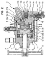
- variable discharge-type high pressure pump P is shown in detail in Fig. 2.
- a drive shaft D which is driven to rotate by the engine E at a one-half rotation speed of the engine is inserted into and supported by a pump housing 1.
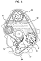
- a pump timing pulley 51 is fixed to the left end part of the drive shaft D so that it may be driven to rotate by a timing belt 52 looped over the outer periphery as shown in Fig. 3.
- a camshaft timing pulley 53 is fixed to the camshaft of the engine, and a crankshaft timing pulley 54 is connected to the crankshaft of the engine.
- the pump timing pulley 51 and the camshaft timing pulley 53 are driven to rotate by rotation of the crankshaft of the engine through the timing belt 52.
- Idlers 55 and 56 are used, so that the idler 56 applies a tension to the timing belt 52 with the spring force of a spring 57 to prevent slacking.
- a vane-type feed pump P1 is coupled with the drive shaft D to supply fuel under low pressure.
- the feed pump p1 rotates with the drive shaft D to suck fuel from the fuel tank T and feeds it at a predetermined feed pressure (about 15 atms) to a fuel reservoir 5a formed inside a head 14 through low pressure flow passage 11, 12 and a low pressure flow passage 13 in the head 14.
- the fuel discharge side and the fuel suction side of the feed pump P1 are connected through a pressure regulating valve not shown, so that the discharge pressure may be regulated.
- the variable discharge-type high pressure pump P houses therein the feed pump P1 shown in Fig. 1.
- the drive shaft D is supported rotatably in the pump housing 1 through bearings D1 and D2.
- An inner cam 8 is integrally formed on its right end part.
- the head 14 is press-fit into the right end opening of the pump housing 1.
- the head 14 has a protrusion at its left end central part to be inserted into the inner cam 8.
- a control valve 6a is disposed in the lower end part of the head 14 to control the amount of low pressure fuel flowing into the pressure chamber, that is, to control the amount of fuel passing between the feed pump P1 and a suction valve 4a described later.
- the suction valve 4a which is a check valve, is disposed in the right end central part of the head 14.
- a delivery valve 3 is disposed above the suction valve 4a.
- another control valve 6b and suction valve 4b are disposed at different positions in addition to the control valve 6a and the suction valve 4a.
- the head 14 is formed with a flow passage 72 leading from the control valve 6a to the suction valve 4a, flow passages 30a and 40a leading from the suction valve 4a to a pressure chamber 23a described later, a discharge port 16a leading from the flow passage 40a to the delivery valve 3.
- the head 14 is also formed with a flow passage 72 leading from the control valve 6a to the suction valve 4b, flow passages 30b and 40b leading from the suction valve 4b to a pressure chamber 23b described later, a discharge port 16b leading from the flow passage 40b to the delivery valve 3.
- the control valve 6a is an electromagnetic-type, and has a housing 61 accommodating a coil 62 therein and a valve body 68 press-fit into the upper end part of the housing 61.
- a valve member 73 is held slidably in a cylinder 69 formed in the valve body 68.
- the control valve 6a is fixed by threading bolts not shown through a flange 63 provided on the outer periphery of the housing.
- An annular flow passage 74a is formed around the upper end part of the valve member 73. The flow passage 74a is communicated with the fuel reservoir 5a through the flow passage 74b, and with the flow passage 72 leading to the suction valve 4a through a flow passage 74c.
- An armature 64 is press-fit fixed to the lower end of the valve member 73 in such a manner that the armature faces a stator 65 with a fixed spacing therebetween.
- the coil 62 is disposed outside the stator 65.
- a spring 67 is disposed in a spring chamber 66 formed inside the stator 65 to bias the armature upward in the figure.
- a generally conical seat surface 75 is formed in the open end of the flow passage 74c so that the top end part of the valve member 73 seats on the seat surface 75 to interrupt the flow passages 74a and 74c under the shown condition that the coil 62 is not powered on.
- the coil 62 is powered on or energized in response to the control signal from the electronic control unit C, the armature 64 is attracted and the top end part of the valve member 73 integral with the armature 64 leaves away from the seat surface 75 so that the flow passages 74a and 74c are opened. It is advantageous to disable pressure-feeding of fuel at the time of breakage of the coil by thus constructing the control valve 6a to close normally, that is, when not powered on.
- the control valve 6b is constructed similarly, although not shown.
- a first cylinder 2a and a second cylinder 2b are formed in the left end central part of the head 14 to define pressure chambers inside the head 14.
- the cylinder 2a and the cylinder 2b are spaced apart with a spacing therebetween in the axial direction of the drive shaft D, so that the axes of the cylinders 2a and 2b cross perpendicularly to each other. Further, the cylinders 2a and 2b are formed in the direction perpendicular to the axis of the drive shaft D.
- a first pair of plungers 21a and 21c are disposed to face each other in the first cylinder 2a, and are supported reciprocably and slidably relative to the cylinder 2a.
- the space defined by the inside wall surface of the cylinder 2a and the end faces of the plungers 21a and 21c provide a first pressure chamber 23a.
- a second pair of plungers 21b and 21d are disposed to face each other in the second cylinder 2b, and are supported reciprocably and slidably relative to the cylinder 2b.
- the space defined by the inside wall surface of the cylinder 2b and the end faces of the plungers 21b and 21d provides a second pressure chamber 23b.
- one plunger 21a is formed shorter than the other plunger 21c.
- the pressure chamber 23a is located at a position slightly displaced from the center of the cylinder 2a.
- the plunger 21d is formed shorter than the other plunger 21b, and the pressure chamber 23b is formed at a position slightly displaced from the center of the cylinder 2b.
- Shoes 24a to 24d are provided at outside end parts of the plungers 21a to 21d.
- Cam rollers 22a to 22d are supported rotatably on the corresponding shoes 24a to 24d.
- the end surfaces of the shoes 24a to 24d are slidable on a shoe guide 15 and a plate 7.
- the shoe guide 15 and the plate 7 are fixed to the head 14 with bolts not shown.
- a washer 76 is inserted between the plate 7 and the drive shaft D, so that the drive shaft D and the washer 6 are rotatable from each other and the washer 6 and the plate 7 are rotatable from each other.
- the inner cam 8 is provided in common relative to the cylinders 2a and 2b, so that the plunger 21a to 21d may be reciprocaly moved within the cylinders 2a and 2b by the rotation of the inner cam 8.
- the inside circumferentail surface of the inner cam 8 is shaped in a cam surface 81 having a plurality of cams.
- the cam rollers 22a to 22d are disposed so that the outside circumferences of the cam rollers 22a to 22d are in sliding contact with the cam surface 81.
- the inside circumferential surface of the inner cam 8 is shaped in an elliptic form, and two cams are formed at equal intervals (at positions to face the plungers 21a and 21c in Fig. 5(A)).
- the suction valve 4a which has the flow passage 43 passing through the housing 42 in the left and right directions and a valve member 44 for opening and closing the flow passage 43.
- the flow passage 43 is enlarged in the middle of its extension in the direction of the pressure chamber 23a (leftward in the figure) to form a conical seat surface 45.
- the valve member 44 is biased in the right direction by a spring 46 held in a spring stopper 41, and seats on the seat surface 45.
- the check valve 4a is normally closed in the normal condition shown in the figure.
- the check valve 4a is so constructed that it opens when the control valve 6a opens to allow low pressure fuel to flow from the fuel reservoir 5a and decrease the pressure in the flow passage 30a (pressure in the pressure chamber 23a).
- the low pressure fuel flows into the pressure chamber 23a through the flow passage 72, annular flow passage 48 provided around the outside circumference of the housing 42, flow passage 49 in the housing 42, flow passage 43, flow passage 50 in the spring stopper 41, and flow passages 30a, 40a provided in the head 14.
- suction valve 4b not shown in Fig. 4 is constructed similarly as the suction valve 4a. As described later, the suction valve 4b also opens when the control valve 6b opens to allow low pressure fuel to flow from the fuel reservoir 5b and decrease the pressure in the flow passage 30b (pressure in the pressure chamber 23b). Low pressure fuel flows into the pressure chamber 23b through the flow passage 72, annular flow passage 48 provided around the outside circumference of the housing 42, flow passage 49 in the housing 42, flow passage 43, flow passage 50 in the spring stopper 41, and flow passages 30b, 40b provided in the head 14. The suction valves 4a and 4b are fixed in the head 14 with screws 47.
- the delivery valve 3 has a check valve function and has balls 31a and 31b as valve members.
- the ball 31a is constructed to open and close the flow passage leading from the discharge port 16a communicated with the pressure chamber 23a
- the ball 31b is constructed to open and close the flow passage leading from the discharge port 16b communicated with the pressure chamber 23b.
- the second pressure-feeding route comprises the cylinder 2b, a pair of plungers 21b, 21d and pressure chamber 23b surrounded by those.
- the first pressure-feeding route and the second pressure-feeding route alternately attain fuel pressure-feeding operation.
- the pressure chamber 23a is communicated with the side of the ball 31a of the delivery valve 3 through the flow passage 40a and the discharge port 16a
- the pressure chamber 23b is communicated with the side of the ball 31b of the delivery valve 3 through the flow passage 40b and the discharge port 16b.
- the ball 31a or the ball 31b opens when the pressure in fuel pressurized in each pressure chamber 23a, 23b, so that fuel is supplied to the common rail R through the supply pipe R1.
- the fuel is discharged alternately through the balls 31a and 31b, because the fuel in the pressure chambers 23a and 23b is pressurized alternately.
- the feed pressure to the common rail R varies with operating conditions of the engine E between 200 to 1200 atms.
- the supply system of low pressure fuel to the pressure chambers 23a and 23b has two routes, one being from the fuel reservoir 5a to the pressure chamber 23a through the control valve 6a, suction valve 4a and the flow passage 30a and the other being from the fuel reservoir 5b to the pressure chamber 23b through the control valve 6b, suction valve 4b and the flow passage 30b.
- cam #1 indicates a lift amount at the points 81a and 81c on the cam surface 81 which faces the plungers 21a and 21c in Fig. 5(A).
- Cam #2 indicates a lift amount at the points 81b and 81d on the cam surface 81 which faces the plungers 21b and 21d in Fig. 5(B).
- TCV #1 indicates a lift amount of the valve member 73 of the control valve 6a
- TCV #2 indicates a lift amount of the valve member 73 of the control valve 6b.
- the cams #1 and #2 repeats radially inward movement and radially outward movement. Because the cylinders 2a and 2b are formed perpendicularly to each other, the cams #1 and #2 are different 180° CA (crankshaft angle) in phase.
- the other pressure chamber 23b (23a) is in the fuel pressure-feeding operation.
- the electronic control units C starts to power on the coil 62 of the control valve 6a in advance before the valve member 73 of the control valve 6a opens at the time of start of moving of the cam #1 in the radially outward direction.
- fuel flows into the pressure chamber 23a from the fuel reservoir 5a through the flow passages 74c, 72 of the control valve 6a, flow passage 43 of the suction valve 4a and flow passages 30a, 40a.
- the plungers 21a and 21c move in the radially outward direction while being pressed down onto the cam surface 81 by the fuel flowing thereinto, so that fuel is sucked as the displacement of the pressure chamber 23a is increased.
- the cam #1 moves to come into the fuel pressure-feeding operation.
- the plungers 21a and 21c do not start moving in the radially inward direction immediately after the cam #1 starts moving for fuel pressure-feeding operation.
- the cam rollers 22a and 22c abut the inner cam 8 to drive the plungers 21a and 21c to move in the radially inward direction through the shoes 24a and 24c.
- the suction valve 4a is closed.
- the control valve 6b is powered on with about 180° CA delay from the control valve 6a in the above period, the cam #2 starts moving to effect suction and fuel pressure-feeding operation in the pressure chamber 23b in the same manner as in the pressure chamber 23a.
- a maximum driving torque is reduced by differentiating the time points of fuel pressure-feeding operation between the pressure chambers 23a and 23b.
- control method for preventing excessive pressure-feeding of fuel to the common rail R is described with reference to flow diagrams of controlling the variable discharge-type high pressure pump P executed in the electronic control unit C.
- a NE-signal hardware interrupt routine is executed at every input of the NE-signal produced 68 times per 720° CA.
- a pulse interval between the input NE-signal and the previous one is measured at step S101, so that the pulse interval may be used in a calculation of engine rotation speed Ne.
- a software interrupt process is called at step S105 in correspondence with CNIRQ, thus ending the NE-signal hardware interrupt routine.
- the cylinder counter PCYLND 0 is set in response to an input of G1-signal from the G1 sensor S3.
- a software interrupt process called at step S105 is described.
- a command injection amount QF of the injector I is calculated at step S202, and a command injection timing AF is calculated at step S203 based on the command injection amount QF and the engine rotation speed Ne.
- a target common rail pressure PF is calculated at step S204 based on the command injection amount QF and the engine rotation speed Ne.
- the common rail pressure PC is read in at step S301, and a power-on period TQF to the injector I is calculated at step S302 based on the actual common rail pressure PC and the command injection amount QF.
- a pump power-on period TF is calculated at step S303 to indicate the valve opening period command value as a command value to the control valves 6a and 6b for controlling the amount of fuel passing between the feed pump 1 and the suction valve 4a and between the feed pump P1 and the suction valve 4b.
- Fig. 11 shows a calculation process of the pump power-on period TF executed at step S303.
- a basic power-on period TFJP is calculated at step S401 based on the command injection amount QF and the target common rail pressure PF.
- the subsequent steps S402 to S406 are for calculating corrective terms which are to be added to or subtracted from the command injection amount QF.
- a proportional compensation amount TFJP is calculated at step S402 from the difference between the common rail pressure PC and the target common rail pressure PF.
- the above corrective terms operates to shorten the pump power-on period TF.
- the integral compensation amount TFJI is updated, it results in that the integral compensation value TFJI will in the end includes component which corresponds to the difference between the abnormal common rail pressure PC at this moment and the target common rail pressure PF. Therefore, this updating is not desired.
- the appropriate compensation amount can be calculated by skipping the updating of the integral compensation amount TFJI based on the above difference at the time of abnormality.
- An electromagnetic valve closing delay compensation amount TFD is calculated at step S405 to compensate for the response delay of closing operation of the control valves 6a and 6b relative to the valve closing signal (interruption of power-on to the coil 62).
- the electromagnetic valve closing delay compensation amount TFD is calculated using the following equation (1), that is, by converting the valve closing delay time TFDB ( ⁇ s) of the control valves 6a and 6b stored preliminarily into the crankshaft angle in accordance with the engine rotation speed Ne.
- TFD TFDB x 6 x Ne x 10 -6
- the pump power-on period TF is calculated at step S406 using the equation (2).
- TF TFJB + TFJP + TFJI - TFD + TFOF
- Fig. 14 shows the power-on process of step S604.
- the routine ends after setting the power-on flag TFON at step S605 and without executing the above power-on process when the pump power-on period TF is shorter than the lower limit value and the common rail pressure PC is higher than the target common rail pressure PF + tolerance value (steps S601 and S602). That is, if the check results at steps S601 and S602 are both affirmative, no fuel is refilled into the common rail in connection with fuel injection from the injectors.
- control valve 6a is not opened when the control conditions to be checked at steps S601 and S602 are satisfied.
- the control valve is opened for a predetermined period in accordance with the required amount of fuel to be refilled in the common rail in connection with the fuel injection from the fuel injector.
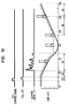
- Fig. 19 showing the conventional method, the control valve is powered on to open at the stage 1 ⁇ .
- the control valve With the opening of the control valve, low pressure fuel flows into the flow passage part (fuel reservoir part) from the control valve to the suction valve, and the pressure in the fuel reservoir part rises from the atmospheric pressure to the feed pressure.
- the suction valve As the suction valve is maintained closed, the pressure in the pressure chamber is the same as that in the common rail and the plunger is pressed to the cam surface.
- the low pressure pump sucks air with fuel from the fuel tank in which the remaining amount of fuel is less such as in fuel shortage condition, air admixes in the fuel supplied to the fuel reservoir part.
- the cam lift decreases with the plunger being pressed to the cam surface and moving in the radially outward direction.
- the displacement of the pressure chamber is increased and the pressure in the pressure chamber is decreased.
- the suction valve is maintained closed, because the pressure in the pressure chamber is higher than the feed pressure.
- the pressure in the pressure chamber decreases below the feed pressure.
- the suction valve opens so that low pressure fuel is sucked into the pressure chamber through the suction valve, even when the control valve has already been closed.
- the pressure in the fuel reservoir part communicated with the pressure chamber further decreases from the feed pressure toward the atmospheric pressure in the same manner as the pressure chamber, and the admixed air in the fuel reservoir part expands. The air expands much more than fuel because of decrease in the pressure, and forces out the fuel in the fuel reservoir part to the pressure chamber.
- the pressure in the pressure chamber increases further, and exceeds the pressure defined by the valve opening pressure of the delivery valve to open the delivery valve.
- the fuel is pressure-fed from the pressure chamber to the common rail R. Because the regulation of the suction amount of fuel into the pressure chamber at the excessive amount side has errors as described above, the fuel is fed excessively.
- the above steps S601 and S602 are executed so that the power-on of the control valve 6a is disabled (step 605) when the influence of shortening of the command power-on period TF and occurrence of excessive pressure-feeding of fuel is large.
- the excessive pressure-feeding of fuel condition can thus be avoided.
- good vehicle driveability and less exhaust gas emission can be attained without causing lessening of pressure controllability.
- variable discharge-type high pressure pump P pressure-feeds fuel to the common rail R alternately from a plurality of pressure chambers 23a and 23b.
- the suction valves 4a and 4b need be provided for the pressure chambers 23a and 23b in one-to-one correspondence.
- the flow passage (fuel reservoir part) 73, 74c, 72, 71a, 48, 49 or 73, 74c, 72, 71b, 48, 49 leading from the control valves 6a, 6b to the suction valves 4a, 4b become lengthened.
- the admixed air which will cause the excessive pressure-feeding of fuel flows into the flow passages, when the feed pump P1 sucks air with fuel. That is, the variable discharge-type high pressure pump P shown in the figures provides an excessive pressure-feeding of fuel preventing effect when controlled according to the control method of the present invention.
- the lower limit value and the tolerance value at steps S601 and S602 are not necessarily limited to the above values. It is preferred to set the values preliminarily through experiments to match the specifications of the variable discharge-type high pressure pump and the like.
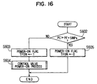
- Fig. 16 shows a control method for a variable discharge-type high pressure pump according to the second embodiment of the present invention.
- step S601 for checking the pump power-on period TF in the first embodiment is skipped, and only step S602 is executed.
- the control conditions for preventing opening of the electromagnetic valves 6a and 6b are limited to only that the common rail pressure PC is higher than the target common rail pressure PF + tolerance value. If affirmative at step S602, the power-on flag TFON is set to 0.
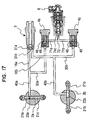
- the present invention may be applied to not only the above variable discharge-type high pressure pump which is constructed to have a control valve and a suction valve for each of a plurality of pressure chambers, but also other types in which low pressure fuel is fed to a pressure chamber through a control valve and a suction valve.
- the pump may be so constructed that low pressure fuel fed out from a feed pump and passing through a common control valve 6 flows into a suction valve 4a through a flow passage 71a and into a suction valve 4b through a flow passage 71b.
- the pump may also be so constructed that the control valve and the suction valve are provided singly for a single pressure chamber as shown in Fig. 18.
- the opening period of a control valve is controlled to control the amount of fuel flowing between a feed pump and a suction valve.
- the control valve is not limited to the above type, but may be a linear solenoid valve type which controls its opening area proportionally.
- the present invention may also be applied to a system in which the amount of fuel is controlled by varying the opening area of the control valve.
- a control valve (6a) and a check valve (4a) are provided from the upstream side in the middle of a flow passage leading from a low pressure pump (P1) to a pressure chamber (23a) which sucks low pressure fuel and pressure-feed it by its expansion and contraction of displacement.
- a variable discharge-type high pressure pump sucks fuel into the pressure chamber (23a) during a period until the control valve (6a) and the check valve (4a) are closed, when the displacement of the pressure chamber (23a) expands.
- the opening of the control valve (6a) is disabled if the pressure in an accumulation chamber is higher than a target pressure by more than a tolerance, so that air admixed in fuel from the low pressure pump (P1) is not allowed to flow into the upstream side of the check valve (4a).
- fuel excess condition in the pressure chamber (23a) which will be caused when the air expands due to lowering of pressure from a feed pressure after closing of the control valve (6a) and forces out fuel into the pressure chamber 23a is avoided, so that excessive pressure-feeding of fuel is prevented.
Landscapes
- Engineering & Computer Science (AREA)
- Chemical & Material Sciences (AREA)
- Combustion & Propulsion (AREA)
- Mechanical Engineering (AREA)
- General Engineering & Computer Science (AREA)
- Fuel-Injection Apparatus (AREA)
- Electrical Control Of Air Or Fuel Supplied To Internal-Combustion Engine (AREA)
Abstract
Description
- A common rail-type fuel injection system is known as one of systems which inject fuel into diesel engines. In the common rail-type injection system, a common accumulation chamber (common rail) communicating with each engine cylinder is provided. The fuel pressure in the accumulation chamber is maintained at a predetermined pressure by pressure-feeding of fuel the necessary amount of high pressure fuel from a variable discharge-type high pressure pump to the accumulation chamber. The high pressure fuel in the accumulation chamber is injected into the combustion chamber of each cylinder from an electromagnetically-operated injector at a predetermined injection timing.
- The variable discharge-type high pressure pump has a pressure chamber which is connected to the common rail and increases/decreases its displacement or volume. The amount of fuel sucked into the pressure chamber is adjusted by opening and closing of a control valve provided between the pressure chamber and a low pressure pump which feeds low pressure fuel.
- A pre-stroke type is generally used to produce the desired feed amount to the common rail by closing the control valve at a predetermined timing when the displacement of the pressure chamber is decreased to set the amount of fuel in the pressure chamber. In the pre-stroke type, however, the control valve is required to operate with high accuracy under high pressure condition because high pressure of fuel is applied to the control valve. The system becomes large and cost increases, if a sufficient pressure-feed amount control characteristics is required.
- A variable discharge-type high pressure pump is proposed as shown in Fig. 18 to solve this problem. In this variable discharge-type high pressure pump, a
drive shaft 101 is extended through and held in apump housing 100. The low pressure fuel is fed into afuel reservoir 105 from a low pressure pump (feed pump) 102 which rotates with thedrive shaft 101 through lowpressure fuel passages - An
inner cam 106 is formed integrally with the right end part of thedrive shaft 101. The left end part of ahead 107 is press-inserted into theinner cam 106. Four cylinders 108 (only two are shown in the figure) are formed in radial directions in the left end part of thehead 107. Aplunger 109 is disposed reciprocally in eachcylinder 108. Apressure chamber 110 is defined by the radial inside end surface of theplunger 109 and the inside wall of thecylinder 108, so that fuel introduced therein may be pressurized by reciprocal movement of theplunger 109. - A
control valve 111 and asuction valve 112 are disposed from the upstream side in the flow passage extending from thefuel reservoir 105 to thepressure chamber 110. Thecontrol valve 111 is an electromagnetic valve the power-on or energization of which is controlled by an electronic control unit not shown. Thesuction valve 112 is a check valve which allows fuel to flow in the forward direction, that is, from thecontrol valve 111 to thepressure chamber 110. - The
suction valve 112 opens when the pressure in thepressure chamber 110 decreases in response to opening of thecontrol valve 111 and increase of the displacement of thepressure chamber 110 due to rearward movement of theplunger 109. It closes when thecontrol valve 111 closes. The flow passage to thepressure chamber 110 is closed by thesuction valve 112 from the start of pressurizing the low pressure fuel to the end of pressure-feeding of fuel, after preliminarily supplying the required amount of fuel from thefeed pump 102 to thepressure chamber 110 in accordance with the valve opening period of thecontrol valve 111. - Thus, the pressure applied to the
control valve 111 is limited at a maximum to the feed pressure (about 15 atms). Therefore, thecontrol valve 111 need not be the type which operates with high accuracy under high pressure conditions, so that a sufficient common rail pressure control may be attained in low cost. - In a control method for the variable discharge-type high pressure pump, for instance, a valve opening period command value of the
control valve 111 is determined in accordance with a fuel injection amount which is the discharge amount of high pressure fuel from the common rail and thecontrol valve 111 is opened and closed in response to the command value to refill the common rail with high pressure fuel. - In the above variable discharge-type high pressure pump, however, excessive pressure-feeding of fuel occurs at the time of engine restarting after fuel shortage, before fuel shortage or at the time of rapid turning. In this instance, it is likely that the normal high controllability of the common rail pressure cannot be attained.
- The present invention has been made in view of the above problem, and has an object to provide a control method and apparatus for variable discharge-type high pressure pumps so that excessive pressure-feeding of fuel is prevented and controllability of pressure in an accumulation chamber is improved.
- According to the present invention, a control valve is controlled in accordance with a command value which is indicative of the amount of flow of fuel, and an accumulation chamber is refilled with high pressure fuel in accordance with the amount of high pressure fuel discharged from a pressure chamber.
- It is checked whether a predetermined control requirement is satisfied. The control requirement includes that a detected actual pressure is higher than a target pressure of the accumulation chamber by more than a predetermined tolerance value, and the control valve is disabled to open thereby stopping suction of the low pressure fuel into the pressure chamber, when it is determined that the control requirement is satisfied.
- When air enters into the fuel discharged from the low pressure pump due to shortage of fuel and causes air to remain in the fuel in a flow passage extending from the control valve to a check valve, the air expands because the check valve opens and the fuel feed pressure decreases with an increase in the displacement of the pressure chamber. This tends to cause that fuel is forced out into the pressure chamber in an amount corresponding to the expansion of air, and fuel is sucked into the pressure chamber excessively. This results in excessive pressure-feeding of fuel.
- However, the control valve is disabled to open when the control requirement is satisfied to indicate a high possibility that air is admixed in the fuel discharged from the low pressure pump. Thus, no air is discharged from the low pressure pump into the flow passage part leading from the control valve to the check valve, so that excessive pressure-feeding of fuel into the accumulation chamber is prevented.
- Fig. 1 is a schematic diagram showing a common rail-type fuel injection system including a variable discharge-type high pressure pump to which the present invention is applied;
- Fig. 2 is a cross-sectional view showing the variable discharge-type high pressure pump shown in Fig. 1;
- Fig. 3 is a side view of an engine showing a driving mechanism for the variable discharge-type high pressure pump;
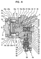
- Fig. 4 is another cross-sectional view showing a part of the variable discharge-type high pressure pump;
- Fig. 5 (A) is a cross-sectional view taken along line A-A in Fig. 4, and (B) is a cross-sectional view taken along line B-B in Fig. 4;
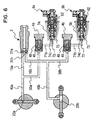
- Fig. 6 is a schematic view showing a main part of the variable discharge-type high pressure pump;
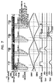
- Fig. 7 is a timing diagram showing operation of the variable discharge-type high pressure pump;
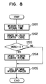
- Fig. 8 is a first flow diagram showing a control method for variable discharge-type high pressure pump;
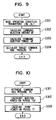
- Fig. 9 is a second flow diagram showing a control method for variable discharge-type high pressure pump;
- Fig. 10 is a third flow diagram showing a control method for variable discharge-type high pressure pump;
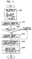
- Fig. 11 is a fourth flow diagram showing a control method for variable discharge-type high pressure pump;
- Fig. 12 is a fifth flow diagram showing a control method for variable discharge-type high pressure pump;
- Fig. 13 is a sixth flow diagram showing a control method for variable discharge-type high pressure pump;
- Fig. 14 is a seventh flow diagram showing a control method for variable discharge-type high pressure pump;
- Fig. 15 is an eighth flow diagram showing a control method for variable discharge-type high pressure pump;
- Fig. 16 is a flow diagram showing another control method for variable discharge-type high pressure pump;
- Fig. 17 is a schematic view showing a main part of another variable discharge-type high pressure pump to which the control method for variable discharge-type high pressure pump according to the present invention;
- Fig. 18 is a cross-sectional view showing a variable discharge-type high pressure pump to which a conventional control method is applied; and
- Fig. 19 is a timing diagram showing operation of the conventional control method for comparison with the control method according to the present invention.
-
- A control method for a variable discharge-type high pressure pump according to the present invention is described with reference to a case in which it is applied a common rail-type fuel injection system for diesel engines.
- In Fig. 1, a plurality of injectors I is mounted on an engine E in correspondence with the combustion chamber of each cylinder. These injectors I are connected to a common rail R which is an accumulation chamber common to each cylinder. The injection of fuel from the injector I into the combustion chamber of the engine E is controlled by on-off of an injection control electromagnetic valve B1. Fuel in the common rail R is injected into the engine E during a period the electromagnetic valve B1 is open. It is assumed that the engine E is a four cylinder-type.
- A variable discharge-type high pressure pump P is connected to the common rail R through a supply pipe R1 and discharge valves B2, so that fuel is continuously accumulated in the common rail R at a high predetermined pressure which corresponds to a fuel injection pressure. The variable discharge-type high pressure pump P pressurizes low pressure fuel sucked from a fuel tank T by a feed pump P1 to high pressure so that fuel in the common rail R is controlled to the predetermined high pressure.
- The common rail injection system has an electronic control unit C. The electronic control unit C is constructed with a generally known hardware including a CPU and the like. It produces control signals to the injectors I and the variable discharge-type high pressure pump P in response to inputs from various sensors S1, S2 and S3, so that the injectors I and the variable discharge-type high pressure pump P may be electronically controlled.
- The electronic control unit C receives engine condition information from, for instance, engine rotation sensor S2 and cylinder discrimination sensor (G1 sensor) S3. The pressure sensor S1 is disposed on the common rail R to detect a common rail pressure, so that information of the common rail pressure is applied to the electronic control unit C.
- The electronic control unit C calculates optimum injection timing and injection amount (injection period) in response to those information, and produces a control signal to the fuel injection control electromagnetic valve B1 so that the discharge amount of the variable discharge-type high pressure pump P is controlled.
- The variable discharge-type high pressure pump P is shown in detail in Fig. 2. In the figure, a drive shaft D which is driven to rotate by the engine E at a one-half rotation speed of the engine is inserted into and supported by a
pump housing 1. Apump timing pulley 51 is fixed to the left end part of the drive shaft D so that it may be driven to rotate by atiming belt 52 looped over the outer periphery as shown in Fig. 3. - In the figure, a
camshaft timing pulley 53 is fixed to the camshaft of the engine, and acrankshaft timing pulley 54 is connected to the crankshaft of the engine. Thepump timing pulley 51 and thecamshaft timing pulley 53 are driven to rotate by rotation of the crankshaft of the engine through thetiming belt 52.Idlers timing belt 52 with the spring force of aspring 57 to prevent slacking. - A vane-type feed pump P1 is coupled with the drive shaft D to supply fuel under low pressure. The feed pump p1 rotates with the drive shaft D to suck fuel from the fuel tank T and feeds it at a predetermined feed pressure (about 15 atms) to a
fuel reservoir 5a formed inside ahead 14 through lowpressure flow passage 11, 12 and a lowpressure flow passage 13 in thehead 14. The fuel discharge side and the fuel suction side of the feed pump P1 are connected through a pressure regulating valve not shown, so that the discharge pressure may be regulated. Thus, the variable discharge-type high pressure pump P houses therein the feed pump P1 shown in Fig. 1. - The drive shaft D is supported rotatably in the
pump housing 1 through bearings D1 and D2. Aninner cam 8 is integrally formed on its right end part. Thehead 14 is press-fit into the right end opening of thepump housing 1. Thehead 14 has a protrusion at its left end central part to be inserted into theinner cam 8. - A
control valve 6a is disposed in the lower end part of thehead 14 to control the amount of low pressure fuel flowing into the pressure chamber, that is, to control the amount of fuel passing between the feed pump P1 and asuction valve 4a described later. Thesuction valve 4a, which is a check valve, is disposed in the right end central part of thehead 14. Adelivery valve 3 is disposed above thesuction valve 4a. Although not shown, anothercontrol valve 6b andsuction valve 4b are disposed at different positions in addition to thecontrol valve 6a and thesuction valve 4a. - As shown in Fig. 4, the
head 14 is formed with aflow passage 72 leading from thecontrol valve 6a to thesuction valve 4a,flow passages suction valve 4a to apressure chamber 23a described later, adischarge port 16a leading from theflow passage 40a to thedelivery valve 3. Although not shown, thehead 14 is also formed with aflow passage 72 leading from thecontrol valve 6a to thesuction valve 4b, flowpassages suction valve 4b to apressure chamber 23b described later, adischarge port 16b leading from theflow passage 40b to thedelivery valve 3. - The
control valve 6a is an electromagnetic-type, and has ahousing 61 accommodating acoil 62 therein and avalve body 68 press-fit into the upper end part of thehousing 61. Avalve member 73 is held slidably in acylinder 69 formed in thevalve body 68. Thecontrol valve 6a is fixed by threading bolts not shown through aflange 63 provided on the outer periphery of the housing. Anannular flow passage 74a is formed around the upper end part of thevalve member 73. Theflow passage 74a is communicated with thefuel reservoir 5a through theflow passage 74b, and with theflow passage 72 leading to thesuction valve 4a through aflow passage 74c. - An
armature 64 is press-fit fixed to the lower end of thevalve member 73 in such a manner that the armature faces astator 65 with a fixed spacing therebetween. Thecoil 62 is disposed outside thestator 65. Aspring 67 is disposed in aspring chamber 66 formed inside thestator 65 to bias the armature upward in the figure. - A generally
conical seat surface 75 is formed in the open end of theflow passage 74c so that the top end part of thevalve member 73 seats on theseat surface 75 to interrupt theflow passages coil 62 is not powered on. When thecoil 62 is powered on or energized in response to the control signal from the electronic control unit C, thearmature 64 is attracted and the top end part of thevalve member 73 integral with thearmature 64 leaves away from theseat surface 75 so that theflow passages control valve 6a to close normally, that is, when not powered on. Thecontrol valve 6b is constructed similarly, although not shown. - A
first cylinder 2a and asecond cylinder 2b are formed in the left end central part of thehead 14 to define pressure chambers inside thehead 14. Thecylinder 2a and thecylinder 2b are spaced apart with a spacing therebetween in the axial direction of the drive shaft D, so that the axes of thecylinders cylinders - As shown in Fig. 5(A), a first pair of
plungers first cylinder 2a, and are supported reciprocably and slidably relative to thecylinder 2a. The space defined by the inside wall surface of thecylinder 2a and the end faces of theplungers first pressure chamber 23a. Similarly, as shown in Fig. 5(B), a second pair ofplungers second cylinder 2b, and are supported reciprocably and slidably relative to thecylinder 2b. The space defined by the inside wall surface of thecylinder 2b and the end faces of theplungers second pressure chamber 23b. - Of the pair of
plungers plunger 21a is formed shorter than theother plunger 21c. As a result, thepressure chamber 23a is located at a position slightly displaced from the center of thecylinder 2a. Similarly, of the pair ofplungers plunger 21d is formed shorter than theother plunger 21b, and thepressure chamber 23b is formed at a position slightly displaced from the center of thecylinder 2b. This construction provides an advantage that theflow passages flow passages -
Shoes 24a to 24d are provided at outside end parts of theplungers 21a to 21d.Cam rollers 22a to 22d are supported rotatably on the correspondingshoes 24a to 24d. The end surfaces of theshoes 24a to 24d are slidable on ashoe guide 15 and aplate 7. Theshoe guide 15 and theplate 7 are fixed to thehead 14 with bolts not shown. Awasher 76 is inserted between theplate 7 and the drive shaft D, so that the drive shaft D and thewasher 6 are rotatable from each other and thewasher 6 and theplate 7 are rotatable from each other. - The
inner cam 8 is provided in common relative to thecylinders plunger 21a to 21d may be reciprocaly moved within thecylinders inner cam 8. The inside circumferentail surface of theinner cam 8 is shaped in acam surface 81 having a plurality of cams. Thecam rollers 22a to 22d are disposed so that the outside circumferences of thecam rollers 22a to 22d are in sliding contact with thecam surface 81. Here, the inside circumferential surface of theinner cam 8 is shaped in an elliptic form, and two cams are formed at equal intervals (at positions to face theplungers - Thus, when the
inner cam 8 integral with the drive shaft D rotates, theplungers cylinder 2a, and theplungers cylinder 2b. Fuel in thepressure chambers plungers plungers - The
suction valve 4a which has theflow passage 43 passing through the housing 42 in the left and right directions and avalve member 44 for opening and closing theflow passage 43. Theflow passage 43 is enlarged in the middle of its extension in the direction of thepressure chamber 23a (leftward in the figure) to form aconical seat surface 45. Thevalve member 44 is biased in the right direction by a spring 46 held in aspring stopper 41, and seats on theseat surface 45. Thus, thecheck valve 4a is normally closed in the normal condition shown in the figure. Thecheck valve 4a is so constructed that it opens when thecontrol valve 6a opens to allow low pressure fuel to flow from thefuel reservoir 5a and decrease the pressure in theflow passage 30a (pressure in thepressure chamber 23a). - During the valve opening period, the low pressure fuel flows into the
pressure chamber 23a through theflow passage 72,annular flow passage 48 provided around the outside circumference of the housing 42,flow passage 49 in the housing 42,flow passage 43,flow passage 50 in thespring stopper 41, and flowpassages head 14. - Another
suction valve 4b not shown in Fig. 4 is constructed similarly as thesuction valve 4a. As described later, thesuction valve 4b also opens when thecontrol valve 6b opens to allow low pressure fuel to flow from thefuel reservoir 5b and decrease the pressure in theflow passage 30b (pressure in thepressure chamber 23b). Low pressure fuel flows into thepressure chamber 23b through theflow passage 72,annular flow passage 48 provided around the outside circumference of the housing 42,flow passage 49 in the housing 42,flow passage 43,flow passage 50 in thespring stopper 41, and flowpassages head 14. Thesuction valves head 14 withscrews 47. - The
delivery valve 3 has a check valve function and hasballs ball 31a is constructed to open and close the flow passage leading from thedischarge port 16a communicated with thepressure chamber 23a, and theball 31b is constructed to open and close the flow passage leading from thedischarge port 16b communicated with thepressure chamber 23b. - That is, as shown in Fig. 6, two plungers are disposed in the two
cylinders cylinder 2b, a pair ofplungers pressure chamber 23b surrounded by those. The first pressure-feeding route and the second pressure-feeding route alternately attain fuel pressure-feeding operation. Thepressure chamber 23a is communicated with the side of theball 31a of thedelivery valve 3 through theflow passage 40a and thedischarge port 16a, and thepressure chamber 23b is communicated with the side of theball 31b of thedelivery valve 3 through theflow passage 40b and thedischarge port 16b. - The
ball 31a or theball 31b opens when the pressure in fuel pressurized in eachpressure chamber balls pressure chambers - The supply system of low pressure fuel to the
pressure chambers fuel reservoir 5a to thepressure chamber 23a through thecontrol valve 6a,suction valve 4a and theflow passage 30a and the other being from thefuel reservoir 5b to thepressure chamber 23b through thecontrol valve 6b,suction valve 4b and theflow passage 30b. - The operation of the variable discharge-type high pressure pump P constructed as above is described with reference to Fig. 7. In the figure,
cam # 1 indicates a lift amount at thepoints cam surface 81 which faces theplungers Cam # 2 indicates a lift amount at thepoints cam surface 81 which faces theplungers TCV # 1 indicates a lift amount of thevalve member 73 of thecontrol valve 6a, andTCV # 2 indicates a lift amount of thevalve member 73 of thecontrol valve 6b. - When the
inner cam 8 rotates, thecams # 1 and #2 repeats radially inward movement and radially outward movement. Because thecylinders cams # 1 and #2 are different 180° CA (crankshaft angle) in phase. During a fuel suction operation in which onepressure chamber 23a (23b) is in no fuel pressure-feeding operation, theother pressure chamber 23b (23a) is in the fuel pressure-feeding operation. - Suction and fuel pressure-feeding operations in the
pressure chambers coil 62 of thecontrol valve 6a in advance before thevalve member 73 of thecontrol valve 6a opens at the time of start of moving of thecam # 1 in the radially outward direction. With thecontrol valve 6a being powered on, fuel flows into thepressure chamber 23a from thefuel reservoir 5a through theflow passages control valve 6a, flowpassage 43 of thesuction valve 4a and flowpassages plungers cam surface 81 by the fuel flowing thereinto, so that fuel is sucked as the displacement of thepressure chamber 23a is increased. - When the electronic control unit C interrupts the power-on of the
coil 62 of thecontrol valve 6a to close thevalve member 73 of thecontrol valve 6a and thesuction valve 4a, the fuel is stopped from flowing into thepressure chamber 23a. Although thecam # 1 continues to move in thereafter, theplungers cam rollers inner cam 8 when the suction operation ends. - Then, the
cam # 1 moves to come into the fuel pressure-feeding operation. Theplungers cam # 1 starts moving for fuel pressure-feeding operation. When the lift amount ofcam # 1 reaches the lift amount of theplungers cam rollers inner cam 8 to drive theplungers shoes suction valve 4a is closed. - Then, as the
plungers pressure chamber 23a, the fuel in thepressure chamber 23a is pressurized and the pressure in thepressure chamber 23a is increased gradually. When the pressure of fuel in thepressure chambers 23a and 23c rises above a predetermined pressure, high pressure fuel is supplied from the supply pipe R1 to the common rail R through thedischarge port 16a and thedelivery valve 3. The fuel pressure-feeding ends when the lift amount of thecam # 1 reaches its maximum and the lift ofplungers - The
control valve 6b is powered on with about 180° CA delay from thecontrol valve 6a in the above period, thecam # 2 starts moving to effect suction and fuel pressure-feeding operation in thepressure chamber 23b in the same manner as in thepressure chamber 23a. Thus, a maximum driving torque is reduced by differentiating the time points of fuel pressure-feeding operation between thepressure chambers - The control method for preventing excessive pressure-feeding of fuel to the common rail R is described with reference to flow diagrams of controlling the variable discharge-type high pressure pump P executed in the electronic control unit C.
- In Fig. 8, a NE-signal hardware interrupt routine is executed at every input of the NE-signal produced 68 times per 720° CA. A pulse interval between the input NE-signal and the previous one is measured at step S101, so that the pulse interval may be used in a calculation of engine rotation speed Ne. A NE-pulse counter CNIRQ is updated (one step increment) at step S102. It is checked at step S103 whether CNIRQ = 0 holds.
- If affirmative (YES) a cylinder counter PCYLND (= 0, 1, 2, 3) is updated (one step increment) at step S104 to proceed to step S105. If negative (NO), the processing advances to step S105. A software interrupt process is called at step S105 in correspondence with CNIRQ, thus ending the NE-signal hardware interrupt routine. Here, the cylinder counter PCYLND = 0 is set in response to an input of G1-signal from the G1 sensor S3.
- The software interrupt process called at step S105 is described. In Fig. 9 showing a software interrupt process called when CNIRQ = 1, the engine rotation speed Ne and accelerator position Ac are read in at step S201. A command injection amount QF of the injector I is calculated at step S202, and a command injection timing AF is calculated at step S203 based on the command injection amount QF and the engine rotation speed Ne. Finally, a target common rail pressure PF is calculated at step S204 based on the command injection amount QF and the engine rotation speed Ne.
- Fig. 10 shows a software interrupt process called when CNIRQ = 3. The common rail pressure PC is read in at step S301, and a power-on period TQF to the injector I is calculated at step S302 based on the actual common rail pressure PC and the command injection amount QF. A pump power-on period TF is calculated at step S303 to indicate the valve opening period command value as a command value to the
control valves feed pump 1 and thesuction valve 4a and between the feed pump P1 and thesuction valve 4b. - Fig. 11 shows a calculation process of the pump power-on period TF executed at step S303. A basic power-on period TFJP is calculated at step S401 based on the command injection amount QF and the target common rail pressure PF. The subsequent steps S402 to S406 are for calculating corrective terms which are to be added to or subtracted from the command injection amount QF. A proportional compensation amount TFJP is calculated at step S402 from the difference between the common rail pressure PC and the target common rail pressure PF.
- It is checked at step S403 whether a power-on flag TFON described later is 1. If the power-on flag TFON = 1, an integral compensation amount TFJI is calculated and updated at step S404 from the difference between the common rail pressure PC and the target common rail pressure PF. If the power-on flag TFON = 0, the calculation of the integral compensation amount TFIJ (step S403) is skipped. As described later, the power-on flag TFON is set to 0 when it is likely that the excessive pressure-feed occurs.
- The above corrective terms operates to shorten the pump power-on period TF. However, if the integral compensation amount TFJI is updated, it results in that the integral compensation value TFJI will in the end includes component which corresponds to the difference between the abnormal common rail pressure PC at this moment and the target common rail pressure PF. Therefore, this updating is not desired. The appropriate compensation amount can be calculated by skipping the updating of the integral compensation amount TFJI based on the above difference at the time of abnormality.
- An electromagnetic valve closing delay compensation amount TFD is calculated at step S405 to compensate for the response delay of closing operation of the
control valves control valves - The pump power-on period TF is calculated at step S406 using the equation (2).
pressure chambers control valves plungers 21a to 23d start moving in the radially outward direction, the power-on period before that time point does not contribute to the suction of fuel. Therefore, as described above, TFOF is added to an effective fuel suction period TFJ ( - Fig. 12 shows a software interrupt called when CHIRQ = 4, the on-timing AF of the injector is set at step S501, and an off-timing tQF of the injector is set at step S502 after the injector-on period (TQF) at the time of the on-timing AF, thus ending this software interrupt.
- Fig. 13 shows a software interrupt called when CNIRQ = 5. It is checked at steps S601 and S602 whether required control conditions are satisfied. It is checked at step S601 whether the pump power-on period TF is shorter than a predetermined lower limit value. The lower limit value is determined preliminarily to 5° CA, for instance. It is checked at step S602 whether the actual common rail pressure PC is higher than the target common rail pressure PF + tolerance value. Here, the tolerance value is set preliminarily to 5 Mpa, for instance. If the check result of either step S601 or S602 is negative, the power-on flag TFON is set to 1 at step S603, and a power-on process is executed at step 604. If both the check results of steps S601 and S602 are affirmative, the following step S605 is executed.
- Fig. 14 shows the power-on process of step S604. The cylinder counter PCYLND is read in at step S701, and it is checked at step S702 whether the PCYLND = 0 or 2. If affirmative, the processing proceeds to step S703 to power on the
control valve 6b. If negative, the processing proceeds to step S704 to power on thecontrol valve 6a, thus ending this power-on process. - Fig. 15 shows a software interrupt called when CNIRQ = 6. The cylinder counter PCYLND is read in at step S801, and it is checked at step S802 whether PCYLND = 0 or 2. If affirmative, the processing proceeds to step S803 to set the power-off timing after the pump power-on period TF from the power-on timing with respect to the
control valve 6b. If negative, the processing proceeds to step S804 to set power-off timing with regard to thecontrol valve 6b, thus ending this routine. - In the above software interrupt process executed when CNIRQ = 5, the routine ends after setting the power-on flag TFON at step S605 and without executing the above power-on process when the pump power-on period TF is shorter than the lower limit value and the common rail pressure PC is higher than the target common rail pressure PF + tolerance value (steps S601 and S602). That is, if the check results at steps S601 and S602 are both affirmative, no fuel is refilled into the common rail in connection with fuel injection from the injectors.
- A difference between the control method according to the present invention and the conventional method is described below. In the control method according to the present invention, the
control valve 6a is not opened when the control conditions to be checked at steps S601 and S602 are satisfied. In the conventional method, the control valve is opened for a predetermined period in accordance with the required amount of fuel to be refilled in the common rail in connection with the fuel injection from the fuel injector. - In Fig. 19 showing the conventional method, the control valve is powered on to open at the
stage 1 ○. With the opening of the control valve, low pressure fuel flows into the flow passage part (fuel reservoir part) from the control valve to the suction valve, and the pressure in the fuel reservoir part rises from the atmospheric pressure to the feed pressure. As the suction valve is maintained closed, the pressure in the pressure chamber is the same as that in the common rail and the plunger is pressed to the cam surface. Here, when the low pressure pump sucks air with fuel from the fuel tank in which the remaining amount of fuel is less such as in fuel shortage condition, air admixes in the fuel supplied to the fuel reservoir part. - At the
following stage 2 ○, the cam lift decreases with the plunger being pressed to the cam surface and moving in the radially outward direction. The displacement of the pressure chamber is increased and the pressure in the pressure chamber is decreased. However, the suction valve is maintained closed, because the pressure in the pressure chamber is higher than the feed pressure. - At the
following stage 3 ○, the pressure in the pressure chamber decreases below the feed pressure. The suction valve opens so that low pressure fuel is sucked into the pressure chamber through the suction valve, even when the control valve has already been closed. The pressure in the fuel reservoir part communicated with the pressure chamber further decreases from the feed pressure toward the atmospheric pressure in the same manner as the pressure chamber, and the admixed air in the fuel reservoir part expands. The air expands much more than fuel because of decrease in the pressure, and forces out the fuel in the fuel reservoir part to the pressure chamber. - Thus, when fuel with admixed air under the feed pressure flows into the fuel reservoir part, the fuel forced out by the expansion of admixed air due to change from the feed pressure to the atmospheric pressure is forced out to the pressure chamber as excessive fuel irrespective of the power-on period of the control valve. As a result, the fuel is not regulated to the amount corresponding to the power-on period of the control valve.
- After the pressure in the pressure chamber decreases to the atmospheric pressure and the cam lift stops decreasing, the cam lift increases again at the
stage 4 ○. The cam starts to press the plunger. Thus, the fuel in the pressure chamber is pressurized, and the pressure in the pressure chamber increases. - At the
following stage 5 ○, the pressure in the pressure chamber increases further, and exceeds the pressure defined by the valve opening pressure of the delivery valve to open the delivery valve. The fuel is pressure-fed from the pressure chamber to the common rail R. Because the regulation of the suction amount of fuel into the pressure chamber at the excessive amount side has errors as described above, the fuel is fed excessively. - Thus, the pressure in the common rail tends to rise excessively. The power-on period TF is shortened to counter this. However, as long as fuel admixed with air from the low pressure pump is sucked, excessive fuel flows into the pressure chamber in the end in an amount corresponding to the air amount. It is thus highly likely that the excessive pressure-feed condition cannot be countered.
- On the contrary, in the control method according to the present invention, the above steps S601 and S602 are executed so that the power-on of the
control valve 6a is disabled (step 605) when the influence of shortening of the command power-on period TF and occurrence of excessive pressure-feeding of fuel is large. The excessive pressure-feeding of fuel condition can thus be avoided. As a result, good vehicle driveability and less exhaust gas emission can be attained without causing lessening of pressure controllability. - Further, the variable discharge-type high pressure pump P pressure-feeds fuel to the common rail R alternately from a plurality of
pressure chambers timing belt 52 can be reduced to prevent lessening of durability. - However, the
suction valves pressure chambers suction valves control valves control valves suction valves - The lower limit value and the tolerance value at steps S601 and S602 are not necessarily limited to the above values. It is preferred to set the values preliminarily through experiments to match the specifications of the variable discharge-type high pressure pump and the like.
- Fig. 16 shows a control method for a variable discharge-type high pressure pump according to the second embodiment of the present invention. In this embodiment, the software interrupt process executed by the electronic control unit C when CNIRQ = 5 is replaced with the software interrupt process shown in Fig. 17 executed when CNIRQ = 5.
- Description is made primarily on the difference from the first embodiment with the same processes being designated with the same reference numerals in the figure.
- In this embodiment, step S601 for checking the pump power-on period TF in the first embodiment is skipped, and only step S602 is executed. The control conditions for preventing opening of the
electromagnetic valves - The excessive pressure-feeding of fuel arising from admixed air can also be prevented in this control method.
- Further, the present invention may be applied to not only the above variable discharge-type high pressure pump which is constructed to have a control valve and a suction valve for each of a plurality of pressure chambers, but also other types in which low pressure fuel is fed to a pressure chamber through a control valve and a suction valve.
- For example, as shown in Fig. 17, the pump may be so constructed that low pressure fuel fed out from a feed pump and passing through a
common control valve 6 flows into asuction valve 4a through aflow passage 71a and into asuction valve 4b through aflow passage 71b. The pump may also be so constructed that the control valve and the suction valve are provided singly for a single pressure chamber as shown in Fig. 18. - In the above embodiments, the opening period of a control valve is controlled to control the amount of fuel flowing between a feed pump and a suction valve. However, the control valve is not limited to the above type, but may be a linear solenoid valve type which controls its opening area proportionally. The present invention may also be applied to a system in which the amount of fuel is controlled by varying the opening area of the control valve.
- A control valve (6a) and a check valve (4a) are provided from the upstream side in the middle of a flow passage leading from a low pressure pump (P1) to a pressure chamber (23a) which sucks low pressure fuel and pressure-feed it by its expansion and contraction of displacement. A variable discharge-type high pressure pump sucks fuel into the pressure chamber (23a) during a period until the control valve (6a) and the check valve (4a) are closed, when the displacement of the pressure chamber (23a) expands. The opening of the control valve (6a) is disabled if the pressure in an accumulation chamber is higher than a target pressure by more than a tolerance, so that air admixed in fuel from the low pressure pump (P1) is not allowed to flow into the upstream side of the check valve (4a). Thus, fuel excess condition in the pressure chamber (23a) which will be caused when the air expands due to lowering of pressure from a feed pressure after closing of the control valve (6a) and forces out fuel into the
pressure chamber 23a is avoided, so that excessive pressure-feeding of fuel is prevented.
Claims (7)
- A control method for a variable discharge-type high pressure pump having a pressure chamber (23a) which is connected to an accumulation chamber (R) for holding high pressure fuel and increases/decreases its displacement, a check valve (4a) which is disposed in a flow passage extending from a low pressure pump (P1) to the pressure chamber in a forward direction from the low pressure pump to the pressure chamber, and a control valve (6a) which is disposed in the flow passage to control the amount of fuel passing between the low pressure pump and the check valve, so that the low pressure fuel is sucked from the low pressure pump into the pressure chamber through the control valve when the pressure chamber increases its displacement, and the fuel in the pressure chamber is pressure-fed into the accumulation chamber when the pressure chamber decreases its displacement, the control method comprising the steps of:controlling (S604) the control valve in accordance with a command indicative of the amount of passing fuel; andrefilling the accumulation chamber with high pressure fuel in accordance with the amount of the high pressure fuel discharged from the pressure chamber,
wherein the control method is characterized by further steps of:checking (S601, S602) whether a control requirement is satisfied, the control requirement including that a detected pressure (PC) in the accumulation chamber is higher than a target pressure (PF) in the accumulation chamber by more than a predetermined tolerance value; anddisabling (S605) the control valve to open thereby stopping suction of the low pressure fuel into the pressure chamber, when it is determined that the control requirement is satisfied. - A control method of claim 1, wherein:the control valve is for varying its opening period in accordance with the command value; andthe control requirement includes that a valve opening period command value (TF) of the control valve is shorter than a predetermined lower limit value.
- A control method of claim 2, wherein:an integral compensation is executed (S404, S406) in a calculation of the valve opening period command value in accordance with an integrated value of a difference between the detected pressure in the accumulation chamber and the target pressure; andupdating (S404) of the integral compensation value is disabled when the control valve is disabled to open.
- A control apparatus comprising:a high pressure pump having a pressure chamber (23a) which is connected to an accumulation chamber (R) for holding high pressure fuel and increases/decreases its displacement;a check valve (4a) which is disposed in a flow passage extending from a low pressure side (T, P1) to the pressure chamber in a forward direction from the low pressure side to the pressure chamber;a control valve (6a) which is disposed in the flow passage to control the amount of fuel passing between the low pressure side and the check valve, so that the low pressure fuel is sucked from the low pressure side into the pressure chamber through the control valve when the pressure chamber increases its displacement, and the fuel in the pressure chamber is pressure-fed into the accumulation chamber when the pressure chamber decreases its displacement; andan electronic control unit (C) for controlling the control valve in accordance with a command indicative of the amount of passing fuel and refilling the accumulation chamber with high pressure fuel in accordance with the amount of the high pressure fuel discharged from the pressure chamber,
wherein the electronic control unit is characterized by disabling (S605) the control valve to open thereby stopping suction of the low pressure fuel into the pressure chamber, when it is determined that a predetermined control requirement is satisfied, the control requirement including that an actual pressure (PC) in the accumulation chamber is higher than a predetermined level variable with to a target pressure (PF) in the accumulation chamber. - A control apparatus of claim 4, wherein:the control valve is for varying its opening period in accordance with the command value; andthe control requirement includes that a valve opening period command value (TF) of the control valve is shorter than a predetermined lower limit value.
- A control apparatus of claim 5, wherein:the electronic control circuit executes an integral compensation in a calculation of the valve opening period command value in accordance with an integrated value of a difference between the detected pressure in the accumulation chamber and the target pressure; andthe electronic control circuit disables its updating of the integral compensation value when the control valve is disabled to open.
- A control apparatus of any one of claims 4 to 6, wherein:the high pressure pump is a variable discharge-type and includes a pair of the pressure chambers, the pressure chambers being displaced away from each other;a pair of plungers reciprocally disposed in each of pressure chambers; andeach pair of plungers is arranged to cross each other so that the plungers in one pressure chamber move in opposite direction from the plungers in another pressure chamber in response to rotation of the engine.
Applications Claiming Priority (4)
| Application Number | Priority Date | Filing Date | Title |
|---|---|---|---|
| JP2038899 | 1999-01-28 | ||
| JP2038899 | 1999-01-28 | ||
| JP35016899A JP3744290B2 (en) | 1999-01-28 | 1999-12-09 | Control method of variable discharge high pressure pump |
| JP35016899 | 1999-12-09 |
Publications (3)
| Publication Number | Publication Date |
|---|---|
| EP1024282A2 true EP1024282A2 (en) | 2000-08-02 |
| EP1024282A3 EP1024282A3 (en) | 2003-05-14 |
| EP1024282B1 EP1024282B1 (en) | 2004-09-15 |
Family
ID=26357331
Family Applications (1)
| Application Number | Title | Priority Date | Filing Date |
|---|---|---|---|
| EP20000100854 Expired - Lifetime EP1024282B1 (en) | 1999-01-28 | 2000-01-17 | Control method and apparatus for variable discharge-type high pressure pumps |
Country Status (3)
| Country | Link |
|---|---|
| EP (1) | EP1024282B1 (en) |
| JP (1) | JP3744290B2 (en) |
| DE (1) | DE60013657T2 (en) |
Families Citing this family (5)
| Publication number | Priority date | Publication date | Assignee | Title |
|---|---|---|---|---|
| JP3960051B2 (en) * | 2002-01-15 | 2007-08-15 | 株式会社デンソー | Accumulated fuel injection system |
| JP4513609B2 (en) * | 2005-03-10 | 2010-07-28 | 株式会社デンソー | Fuel injection control device |
| DE102006000459B4 (en) * | 2005-09-15 | 2016-04-07 | Denso Corporation | Fuel injection control device |
| JP2007327404A (en) * | 2006-06-07 | 2007-12-20 | Denso Corp | Common rail type fuel injection device |
| JP4605129B2 (en) * | 2006-09-19 | 2011-01-05 | 株式会社デンソー | Fuel pressure control device |
Citations (3)
| Publication number | Priority date | Publication date | Assignee | Title |
|---|---|---|---|---|
| EP0816672A2 (en) * | 1996-07-05 | 1998-01-07 | Nippon Soken, Inc. | High-pressure pump for use in fuel injection system for diesel engine |
| EP0936352A2 (en) * | 1998-02-10 | 1999-08-18 | Toyota Jidosha Kabushiki Kaisha | Fluid pump control apparatus and method |
| EP0964150A2 (en) * | 1998-04-15 | 1999-12-15 | Denso Corporation | Fuel injection system for internal combustion engine |
-
1999
- 1999-12-09 JP JP35016899A patent/JP3744290B2/en not_active Expired - Fee Related
-
2000
- 2000-01-17 DE DE2000613657 patent/DE60013657T2/en not_active Expired - Lifetime
- 2000-01-17 EP EP20000100854 patent/EP1024282B1/en not_active Expired - Lifetime
Patent Citations (3)
| Publication number | Priority date | Publication date | Assignee | Title |
|---|---|---|---|---|
| EP0816672A2 (en) * | 1996-07-05 | 1998-01-07 | Nippon Soken, Inc. | High-pressure pump for use in fuel injection system for diesel engine |
| EP0936352A2 (en) * | 1998-02-10 | 1999-08-18 | Toyota Jidosha Kabushiki Kaisha | Fluid pump control apparatus and method |
| EP0964150A2 (en) * | 1998-04-15 | 1999-12-15 | Denso Corporation | Fuel injection system for internal combustion engine |
Also Published As
| Publication number | Publication date |
|---|---|
| JP3744290B2 (en) | 2006-02-08 |
| JP2000282938A (en) | 2000-10-10 |
| EP1024282A3 (en) | 2003-05-14 |
| DE60013657D1 (en) | 2004-10-21 |
| DE60013657T2 (en) | 2005-09-29 |
| EP1024282B1 (en) | 2004-09-15 |
Similar Documents
| Publication | Publication Date | Title |
|---|---|---|
| EP2010780B1 (en) | Fuel supply system for an internal combustion engine | |
| KR100289918B1 (en) | Control device of fuel pump | |
| EP2004971B1 (en) | Start-up control device and start-up control method for internal combustion engine | |
| US6840220B2 (en) | Common rail fuel injection control device | |
| US6668800B2 (en) | Internal combustion engine fuel injection system | |
| US7387136B2 (en) | Fuel pressure regulation valve | |
| US20070051340A1 (en) | Fuel injection system monitoring abnormal pressure in inlet of fuel pump | |
| JP2004239168A (en) | Fuel-supply system of internal combustion engine | |
| JP4045594B2 (en) | Accumulated fuel injection system | |
| EP1024282B1 (en) | Control method and apparatus for variable discharge-type high pressure pumps | |
| JP3577991B2 (en) | Common rail fuel pressure control system for internal combustion engines | |
| US6966301B2 (en) | Accumulator fuel system | |
| EP0902181A2 (en) | Variable-discharge-rate high-pressure pump | |
| JP2007211653A (en) | Fuel injection device for internal combustion engine | |
| JP2007046501A (en) | High-pressure fuel supply device | |
| WO2010109967A1 (en) | Common rail pressure control device, control method, and accumulator fuel injection device | |
| JPH0730732B2 (en) | Accumulation type fuel supply device | |
| JP4407647B2 (en) | Fuel injection device for internal combustion engine | |
| JPH11257191A (en) | Variable displacement high-pressure pump | |
| JP3699596B2 (en) | Variable discharge high pressure pump | |
| JP2002130026A (en) | Pressure controller for high-pressure fuel supply system | |
| JP2006152852A (en) | Fuel line of internal combustion engine | |
| JPH1162763A (en) | Inner cam type high pressure fuel feed pump and accumulator type fuel injection device provided therewith | |
| JP2013092071A (en) | Control device for internal combustion engine and internal combustion engine | |
| JPH1182222A (en) | Common-rail fuel injection controller |
Legal Events
| Date | Code | Title | Description |
|---|---|---|---|
| PUAI | Public reference made under article 153(3) epc to a published international application that has entered the european phase |
Free format text: ORIGINAL CODE: 0009012 |
|
| AK | Designated contracting states |
Kind code of ref document: A2 Designated state(s): AT BE CH CY DE DK ES FI FR GB GR IE IT LI LU MC NL PT SE |
|
| AX | Request for extension of the european patent |
Free format text: AL;LT;LV;MK;RO;SI |
|
| PUAL | Search report despatched |
Free format text: ORIGINAL CODE: 0009013 |
|
| RIC1 | Information provided on ipc code assigned before grant |
Ipc: 7F 02D 41/38 A Ipc: 7F 02M 63/02 B Ipc: 7F 02M 59/06 B Ipc: 7F 02M 59/36 B Ipc: 7F 02M 55/00 B |
|
| AK | Designated contracting states |
Designated state(s): AT BE CH CY DE DK ES FI FR GB GR IE IT LI LU MC NL PT SE |
|
| AX | Request for extension of the european patent |
Extension state: AL LT LV MK RO SI |
|
| 17P | Request for examination filed |
Effective date: 20030805 |
|
| 17Q | First examination report despatched |
Effective date: 20030915 |
|
| AKX | Designation fees paid |
Designated state(s): DE FR GB |
|
| GRAP | Despatch of communication of intention to grant a patent |
Free format text: ORIGINAL CODE: EPIDOSNIGR1 |
|
| GRAS | Grant fee paid |
Free format text: ORIGINAL CODE: EPIDOSNIGR3 |
|
| GRAA | (expected) grant |
Free format text: ORIGINAL CODE: 0009210 |
|
| AK | Designated contracting states |
Kind code of ref document: B1 Designated state(s): DE FR GB |
|
| REG | Reference to a national code |
Ref country code: GB Ref legal event code: FG4D |
|
| REG | Reference to a national code |
Ref country code: IE Ref legal event code: FG4D |
|
| REF | Corresponds to: |
Ref document number: 60013657 Country of ref document: DE Date of ref document: 20041021 Kind code of ref document: P |
|
| PLBE | No opposition filed within time limit |
Free format text: ORIGINAL CODE: 0009261 |
|
| STAA | Information on the status of an ep patent application or granted ep patent |
Free format text: STATUS: NO OPPOSITION FILED WITHIN TIME LIMIT |
|
| REG | Reference to a national code |
Ref country code: GB Ref legal event code: 746 Effective date: 20050704 |
|
| ET | Fr: translation filed | ||
| 26N | No opposition filed |
Effective date: 20050616 |
|
| PGFP | Annual fee paid to national office [announced via postgrant information from national office to epo] |
Ref country code: DE Payment date: 20140122 Year of fee payment: 15 |
|
| PGFP | Annual fee paid to national office [announced via postgrant information from national office to epo] |
Ref country code: FR Payment date: 20140123 Year of fee payment: 15 |
|
| PGFP | Annual fee paid to national office [announced via postgrant information from national office to epo] |
Ref country code: GB Payment date: 20140121 Year of fee payment: 15 |
|
| REG | Reference to a national code |
Ref country code: DE Ref legal event code: R119 Ref document number: 60013657 Country of ref document: DE |
|
| GBPC | Gb: european patent ceased through non-payment of renewal fee |
Effective date: 20150117 |
|
| PG25 | Lapsed in a contracting state [announced via postgrant information from national office to epo] |
Ref country code: DE Free format text: LAPSE BECAUSE OF NON-PAYMENT OF DUE FEES Effective date: 20150801 Ref country code: GB Free format text: LAPSE BECAUSE OF NON-PAYMENT OF DUE FEES Effective date: 20150117 |
|
| REG | Reference to a national code |
Ref country code: FR Ref legal event code: ST Effective date: 20150930 |
|
| PG25 | Lapsed in a contracting state [announced via postgrant information from national office to epo] |
Ref country code: FR Free format text: LAPSE BECAUSE OF NON-PAYMENT OF DUE FEES Effective date: 20150202 |