EP1024058A2 - Wire harness protector - Google Patents
Wire harness protector Download PDFInfo
- Publication number
- EP1024058A2 EP1024058A2 EP00300003A EP00300003A EP1024058A2 EP 1024058 A2 EP1024058 A2 EP 1024058A2 EP 00300003 A EP00300003 A EP 00300003A EP 00300003 A EP00300003 A EP 00300003A EP 1024058 A2 EP1024058 A2 EP 1024058A2
- Authority
- EP
- European Patent Office
- Prior art keywords
- wire harness
- members
- axle
- protector
- protector according
- Prior art date
- Legal status (The legal status is an assumption and is not a legal conclusion. Google has not performed a legal analysis and makes no representation as to the accuracy of the status listed.)
- Granted
Links
- 230000001012 protector Effects 0.000 title claims abstract description 48
- 210000000078 claw Anatomy 0.000 description 12
- 238000006073 displacement reaction Methods 0.000 description 4
- 229920003023 plastic Polymers 0.000 description 2
- 239000004033 plastic Substances 0.000 description 2
- 230000002411 adverse Effects 0.000 description 1
- 238000005452 bending Methods 0.000 description 1
- 238000010586 diagram Methods 0.000 description 1
- 238000003780 insertion Methods 0.000 description 1
- 230000037431 insertion Effects 0.000 description 1
- 239000000463 material Substances 0.000 description 1
- 238000000034 method Methods 0.000 description 1
- 230000000717 retained effect Effects 0.000 description 1
Images


Classifications
-
- B—PERFORMING OPERATIONS; TRANSPORTING
- B60—VEHICLES IN GENERAL
- B60R—VEHICLES, VEHICLE FITTINGS, OR VEHICLE PARTS, NOT OTHERWISE PROVIDED FOR
- B60R16/00—Electric or fluid circuits specially adapted for vehicles and not otherwise provided for; Arrangement of elements of electric or fluid circuits specially adapted for vehicles and not otherwise provided for
- B60R16/02—Electric or fluid circuits specially adapted for vehicles and not otherwise provided for; Arrangement of elements of electric or fluid circuits specially adapted for vehicles and not otherwise provided for electric constitutive elements
- B60R16/0207—Wire harnesses
- B60R16/0215—Protecting, fastening and routing means therefor
Definitions
- the present invention relates to a wire harness protector provided on a door opening and closing member of an automobile.
- this wire harness protector is for double doors which open out from the rear of a vehicle main body.
- the wire harness protector reliably protects the wire harness when it moves with the doors and when these doors are opened out to greater than 90°.
- a wire harness provided on a body of an automobile is attached to various types of electrical and electronic devices.
- a wire harness is provided on the rear door of an automobile to operate the tail lamp, the rear wiper, etc.
- This harness is provided with a protector within which the wire harness is housed, this protector moving with the door in order to protect the wire harness and to prevent it from becoming exposed in the vicinity of the door hinges, and thus pinched.
- Fig. 11 of this specification shows a wire harness protector 1 described in JP 4-11751.
- This protector 1 is attached to rear double doors capable of opening out to approximately 90°.
- the protector 1 is attached in the vicinity of a hinge H of a door D, the interior of the wire harness protector 1 housing a wire harness W/H passing to the door D from the interior of a body S, the wire harness protector 1 thereby protecting the wire harness W/H.
- the prior wire harness protector 1 comprises a first fixed member 2 which fits to the door D and a second fixed member 3 which fits to a car body panel P.
- the first fixed member 2 has a cylindrical member 2a which is closed at the base, an outer fitting member 2b within the central portion of the cylindrical member 2a, and a duct member 2d protruding from the cylindrical member 2a approximately horizontally.
- the second fixed member 3 has a cylindrical member 3a which is closed at the top, a tubular axle is 3b within the central portion of the cylindrical member 3a, and a duct member 3d protruding from the cylindrical member 3a approximately horizontally.
- An inner circumference face of the outer fitting member 2b of the first fixed member 2 is provided with a groove 2c and, as shown in Fig. 13, a central portion of an outer base face 2e of the cylindrical member 2a is provided with a concave recess 2f which has a second base face 2g.
- An outer circumference face of the tubular axle 3b is provided with a stopping protrusion 3c.
- the stopping protrusion 3c of the axle 3b is positioned against the groove 2c of the outer fining member 2b. Then the axle 3b is inserted into the outer fining member 2b. As Fig. 13 shows, the stopping protrusion 3c is now in a position whereby it protrudes to the exterior from the second base face 2g of the concave recess 2f and therefore retains it, and an upper face of a circumference wall of the cylindrical member 2a and a lower face of a circumference wall of the cylindrical member 3a make contact.
- the wire harness protector 1 is fixed to the car body panel P and the rear door D.
- the first fixed member 2 and the second fixed member 3 rotate relatively, with the outer fitting member 2b and the tubular axle 3b serving as the centre.
- the stopping protrusion 3c and the groove 2c reach the same position.
- the stopping protrusion 3c can enter the groove 2c as a result of vertical displacement, thereby preventing the first fixed member 2 and the second fixed member 3 from rotating.
- the stopping protrusion 3c, the axle 3b, or another component may break, and the first fixed member 2 and the second fixed member 3 may separate.
- the upper face of the circumference wall of the cylindrical member 2a and the lower face of the circumference wall of the cylindrical member 3a make contact while the first fixed member 2 and the second fixed member 3 are moving relatively.
- the width of these contacting faces is rather thin and there is the problem that slippage occurs between these contacting faces due to displacement in a horizontal direction.
- slippage between these contacting faces occurs, there is the problem that the inner face of one circumference wall chafes against the outer face of the other circumference wall. This either prevents rotation or creates a space between the circumference walls from which the wire harness might be caught and damaged.
- the double doors D are capable of opening out to a range of 90°
- some double doors for a variety of purposes are capable of opening out to 270°. Consequently there is the problem that, since the wire harness protector 1 is designed for a door opening angle of approximately 90°, if it were to be used for a door opening out to 270°, interference would occur between the duct member 2d, the duct member 3d, etc., and movement would be impossible beyond approximately 90°.
- the present invention has taken the above problems into consideration, and aims firstly to present a wire harness protector suitable for doors opening out to 270°. Secondly, it aims to present a wire harness protector wherein a stopping member or contact faces of circumference walls will not prevent relative movement.
- a wire harness protector for a wire harness extending between a body and a door, the door being adapted for pivoting movement through 270°
- the protector comprising a first member adapted for fixing to a body, a second member adapted for fixing to a door, and an elongate member extending between the first and second members, the elongate member having opposite ends respectively pivoted to said first and second members, wherein the first and second members each include an upright cup having an upstanding axle member on the interior base thereof, and the elongate member has upturned cups at the ends thereof, each upturned cup having a depending axle member on the interior base thereof, said upstanding and depending axle members being mutually engageable to permit relative swivelling movement, and said upright and upturned cups being mutually engageable to define hollow chambers around said axle members whereby a wire harness can extend from said first member to said second member via said chambers and said elongate member.
- the axle members are tubular, and in a preferred embodiment they engage telescopically.
- an inner axle member may have a slotted end, and radial protrusions at the top thereof for engagement over the exterior base of the cup of the exterior axle member.
- this slotted end is resilient, and preferably moulded of plastics material.
- the upturned and upright cups may partially nest to define harness receiving chambers, respective circumferential walls preferably being relieved to bear upon one another. These circumferential walls preferably have the same diameter and wall thickness.
- Each of the first, second and elongate members may define a channel linking said chambers, and for receiving a wire harness.
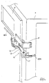
- Fig. 1 shows a wire harness protector 10 of the present invention in a state whereby it is attached to an opening and closing member of rear doors D' of an automobile.
- the doors D' are left and right double doors which are attached by hinges H' to the left and right ends of body panels P at both open sides of the rear of the automobile. These hinges H' allow the doors D' to open from a closed state to a maximum of 270°.
- a wire harness W/H for rear wipers or the like passes to the doors D' from the body panels P.
- the wire harness W/H is kept protected within the interior of the wire harness protectors 10 in the opening and closing members of the doors D'.
- the wire harness protector 10 shown in Fig. 2, is moulded of plastic and comprises three parts; a first fixed member 11, a second fixed member 12, and a rotating member 13.
- the first fixed member 11 and the second fixed member 12 are joined to the two ends of the rotating member 13 in a manner whereby they are capable of swivelling.
- Fig. 3 shows the first fixed member 11 which is fixed to the car body panel P.
- the first fixed member 11 has a cylindrical member 11a which is closed at the base and has a tubular main axle 11b protruding from the central portion of a base face of the cylindrical member 11a.
- the outer diameter of the axle 11b although large enough to maintain the strength of the structure, is less than the inner diameter of an outer fitting cylinder 13b of the rotating member 13 (to be explained), having at most 0.2mm clearance. This ensures smooth rotation.
- Notches 11e are provided at four intervals around the outer circumference of the upper edge of the axle 11b.
- Locking claws 11c protruding from an outer circumference face are provided on four tips which remain between the cut-out notches.
- the upper face of each locking claw 11c is tapered to allow easy insertion.
- the number of notches 11e and locking claws 11c is not restricted to four. A plurality thereof, such as three or five, is equally suitable.
- an inner fitting member 11j is formed by cutting into the upper edge of an upper outer circumference 11i of a circumference wall of the cylindrical member 11a. Specifically, the outer face of the circumference wall of the upper outer circumference 11i is cut into to form a step, the upper outer circumference 11i thereby forming a cross-sectional L-shape.
- the height T1 of the inner fitting member 11j is determined by taking into consideration the vertical displacement when the first fixed member 11 and the rotating member 13 are fitted together. Even when this displacement is at its maximum, it is designed not be elevated above any fitting members.
- a portion of the outer circumference of the cylindrical member 11a is cut into to form a wire harness through member 11f.
- a duct member 11d for housing the wire harness protruded approximately horizontally from this outer circumference of the cylindrical member 11a at a location aligned with the wire harness through member 11f.
- the duct member 11d is provided with a stopping member 11g which has a bolt hole 11h. The direction in which the duct member 11d protrudes may be changed so as to correspond with the direction of distribution of the wire harness.
- Fig. 5 shows the second fixed member 12 which is fixed to the door D'.
- the second fixed member 12 has approximately the same configuration and shape as the first fixed member 11. That is, the second fixed member 12 has a cylindrical member 12a which is closed at the base and a tabular axle 12b protruding from the central portion of a base face of the cylindrical member 12a. The upper edge of the axle 12b is provided with notches 12e and locking claws 12e provided on the remaining tips. Furthermore, an inner fitting member 12j is formed by cuffing into the upper edge of an upper outer circumference 12i of a circumference wall of the cylindrical member 12a, and a portion of the outer circumference of the cylindrical member 12a is cut into to form a wire harness through member 12f.
- a duct member 12d for housing the wire harness protrudes approximately diagonally upwards from this outer circumference of the cylindrical member 12a at a location aligned with the wire harness through member 12f.
- the duct member 12d is provided with a stopping member 12g which has a bolt hole 12h.
- the dimensions of the outer circumference of the axle 12b, and the height of the inner fitting member 12j, are identical with that of the first fixed member 11.
- the rotating member 13 shown in Fig. 6 is provided with a first cylindrical member 13a-1 and a second cylindrical member 13a-2. These are closed at the top and an outer fitting cylinder 13b-1 and an outer fitting cylinder 13a-2 protrude downwards from the central portion of cylindrical upper faces thereof.
- a connecting frame 13d within which the wire harness is housed, extends between the pair of cylindrical members.
- the connecting frame 13d is provided with a stopping member 13g which has a bolt hole 13h.
- the outer fitting cylinders 13b-1 and 13b-2 are cylindrical in shape and fit around the axles 11b and 12b of the first fixed member 11 and the second fixed member 12. This allows the axles 11b and 12b to have clearance to swivel.
- Grooves 13f-1 and 13f-2 are provided on upper faces 13e-1 and 13e-2 of the first cylindrical member 13a-1 and the second cylindrical member 13a-2. These grooves 13f-1 and 13f-2 adjoin with the edge circumference of tabular inner faces of the outer fitting cylinders 13b-1 and 13b-2.
- the grooves 13f-1 and 13f-2 have second lower faces 13g-1 and 13g-2 which are lower than the upper faces 13e-1 and 13e-2 by a height T2. This height T2 is slightly greater than the height of the locking claws 11c and 12c of the first fixed member 11 and the second fixed member 12 and, in a joined state, the locking claws 11c and 12c are retained in a housed state within the grooves 13f-1 and 13f-2.
- grooves 13f-1 and 13f-2 need not be provided in the case where it is not a particular problem if the locking claws 11c and 12c protrude above the upper faces 13e-1 and 13e-2 when the locking claws 11c and 12c are engaged.
- the outer fitting members 13j-1 and 13j-2 are cut into lower edges of lower inner circumstances 13i-1 and 13i-2 of the first cylindrical member 13a-1 and the second cylindrical member 13a-2.
- the inner faces of the circumference walls of the lower inner circumferences 13i-1 and 13i-2 are cut into to form a step, the lower inner circumferences 13i-1 and 13i-2 thereby forming a cross-sectionally L-shape.
- the inner diameters of the outer fitting members 13j-1 and 13j-2 are at most 0.1mm greater than the outer diameter of the inner fitting members 11i and 12j of the first and second fixed members 11 and 12, thereby permitting satisfactory rotation when these are joined together.
- the wire harness W/H is housed within the wire harness protector 10 comprising the first fixed member 11, the second fixed member 12 and the rotating member 13 as shown in Fig. 8. Firstly, while the first fixed member 11, etc. are in a separated state, the wire harness W/H, which comes from the car body panel P, is passed along the interior of the duct member 11d of the first fixed member 11 and is wound in a spiral several times around the outer circumference face of the outer fitting cylinder 13b-1 of the rotating member 13.
- the wire harness W/H is passed along a space between the first cylindrical member 13a-1 along the interior of the connecting frame 13d, wound in a spiral several times around the outer circumference face of the outer fitting cylinder 13b-2 of the second cylindrical member 13a-2, passed along the interior of the duct member 12d of the second fixed member 12, and finally goes to the door D'.
- the first cylindrical member 13a-1 and the second cylindrical member 13a-2 are fitted onto the first fixed member 11 and the second fixed member 12.
- the axle 11b of the first fixed member 11 is inserted into the interior of the outer fitting cylinder 13b-1 of the rotating member 13.
- the locking claws 11c protrude from the upper edge of the axle 11b, and the notches 11e are formed in the remaining space between these locking claws 11c.
- the axle 11b is inserted, the upper edge thereof becomes narrower in diameter by bending inwards into the space provided by the notches 11e, and the axle 11b is passed through the interior of the outer fitting cylinder 13b-1 in this state.
- the locking claws 11c return to their original shape and fit with the second lower face 13g-1 of the groove 13f-1.
- the first fixed member 11 and the rotating member 13 are thereby joined in a state whereby swivelling is possible.
- the first fixed member 11 is fixed to the car body panel P by a bolt which is passed through the stopping member 11 g
- the second fixed member 12 thereof is fixed to the door D' by a bolt which is passed through the stopping member 12g
- the rotating member 13 thereof is fixed to the hinge H' by a bolt which is passed through the stopping member 13g.
- the wire harness protector 10 which is attached to the door D' is capable of rotating from a closed state to a fully open state of 270°.
- the centre of rotation is provided at two locations, the joining member of the first fixed member 11 and the rotating member 13 rotating to 150° and the joining member of the second fixed member 12 and the rotating member 13 rotating to 120°, resulting in a total rotation of 270°.
- the angle of rotation of these joining members is not limited to that of the above embodiment. Each of these joining members may be suitably modified as long as the total angle of rotation is 270°.
- the embodiment is not limited to having the first fixed member 11, the second fixed member 12, and the rotating member 13.
- the joining configuration of the embodiment described above may be reversed, wherein a first and a second fixed member are provided with outer fitting cylinders and a rotating member is provided with a tubular axle having locking claws.
- the present embodiment is not suitable only for double doors, but is also suitable for single doors which open and close from the side and open to a range of 270°.
- the wire harness protector of the present invention reliably protects a wire harness coming from the panel of a car body by pivoting with the opening and closing of the door even when the door has an opening range of 270°. Moreover, the pivoting members of the wire harness protector maintain the same joined state irrespective of the position to which they are pivoted, and consequently pivoting is not adversely affected. Further, even the contacting members of the circumference walls of the cylindrical members are kept together during movement. As a result, satisfactory movement can be reliably maintained.
Landscapes
- Engineering & Computer Science (AREA)
- Mechanical Engineering (AREA)
- Electric Cable Arrangement Between Relatively Moving Parts (AREA)
- Details Of Indoor Wiring (AREA)
- Supports For Pipes And Cables (AREA)
Abstract
Description
- The present invention relates to a wire harness protector provided on a door opening and closing member of an automobile. Specifically, this wire harness protector is for double doors which open out from the rear of a vehicle main body. The wire harness protector reliably protects the wire harness when it moves with the doors and when these doors are opened out to greater than 90°.
- A wire harness provided on a body of an automobile is attached to various types of electrical and electronic devices. A wire harness is provided on the rear door of an automobile to operate the tail lamp, the rear wiper, etc. This harness is provided with a protector within which the wire harness is housed, this protector moving with the door in order to protect the wire harness and to prevent it from becoming exposed in the vicinity of the door hinges, and thus pinched.
- Fig. 11 of this specification shows a
wire harness protector 1 described in JP 4-11751. Thisprotector 1 is attached to rear double doors capable of opening out to approximately 90°. Theprotector 1 is attached in the vicinity of a hinge H of a door D, the interior of thewire harness protector 1 housing a wire harness W/H passing to the door D from the interior of a body S, thewire harness protector 1 thereby protecting the wire harness W/H. - As Fig. 12 shows, the prior
wire harness protector 1 comprises a first fixedmember 2 which fits to the door D and a second fixedmember 3 which fits to a car body panel P. The first fixedmember 2 has acylindrical member 2a which is closed at the base, anouter fitting member 2b within the central portion of thecylindrical member 2a, and aduct member 2d protruding from thecylindrical member 2a approximately horizontally. - The second fixed
member 3 has acylindrical member 3a which is closed at the top, a tubular axle is 3b within the central portion of thecylindrical member 3a, and aduct member 3d protruding from thecylindrical member 3a approximately horizontally. An inner circumference face of theouter fitting member 2b of the first fixedmember 2 is provided with agroove 2c and, as shown in Fig. 13, a central portion of anouter base face 2e of thecylindrical member 2a is provided with aconcave recess 2f which has a second base face 2g. An outer circumference face of thetubular axle 3b is provided with a stoppingprotrusion 3c. - To join the first fixed
member 2 and the second fixed member together, after housing the wire harness W/H, the stoppingprotrusion 3c of theaxle 3b is positioned against thegroove 2c of theouter fining member 2b. Then theaxle 3b is inserted into the outer finingmember 2b. As Fig. 13 shows, the stoppingprotrusion 3c is now in a position whereby it protrudes to the exterior from the second base face 2g of theconcave recess 2f and therefore retains it, and an upper face of a circumference wall of thecylindrical member 2a and a lower face of a circumference wall of thecylindrical member 3a make contact. - In this state, the
wire harness protector 1 is fixed to the car body panel P and the rear door D. When the door is opened or closed, the first fixedmember 2 and the second fixedmember 3 rotate relatively, with theouter fitting member 2b and thetubular axle 3b serving as the centre. - However, during relative movement of the first fixed
member 2 and the second fixedmember 3, the stoppingprotrusion 3c and thegroove 2c reach the same position. At this juncture, there is the problem that the stoppingprotrusion 3c can enter thegroove 2c as a result of vertical displacement, thereby preventing the first fixedmember 2 and the second fixedmember 3 from rotating. There is the danger that, if rotation is forced in this state, the stoppingprotrusion 3c, theaxle 3b, or another component may break, and the first fixedmember 2 and the second fixedmember 3 may separate. - Furthermore, the upper face of the circumference wall of the
cylindrical member 2a and the lower face of the circumference wall of thecylindrical member 3a make contact while the first fixedmember 2 and the second fixedmember 3 are moving relatively. The width of these contacting faces is rather thin and there is the problem that slippage occurs between these contacting faces due to displacement in a horizontal direction. When slippage between these contacting faces occurs, there is the problem that the inner face of one circumference wall chafes against the outer face of the other circumference wall. This either prevents rotation or creates a space between the circumference walls from which the wire harness might be caught and damaged. - Moreover, although the double doors D are capable of opening out to a range of 90°, some double doors for a variety of purposes, are capable of opening out to 270°. Consequently there is the problem that, since the
wire harness protector 1 is designed for a door opening angle of approximately 90°, if it were to be used for a door opening out to 270°, interference would occur between theduct member 2d, theduct member 3d, etc., and movement would be impossible beyond approximately 90°. - The present invention has taken the above problems into consideration, and aims firstly to present a wire harness protector suitable for doors opening out to 270°. Secondly, it aims to present a wire harness protector wherein a stopping member or contact faces of circumference walls will not prevent relative movement.
- According to the invention, there is provided a wire harness protector for a wire harness extending between a body and a door, the door being adapted for pivoting movement through 270°, the protector comprising a first member adapted for fixing to a body, a second member adapted for fixing to a door, and an elongate member extending between the first and second members, the elongate member having opposite ends respectively pivoted to said first and second members, wherein the first and second members each include an upright cup having an upstanding axle member on the interior base thereof, and the elongate member has upturned cups at the ends thereof, each upturned cup having a depending axle member on the interior base thereof, said upstanding and depending axle members being mutually engageable to permit relative swivelling movement, and said upright and upturned cups being mutually engageable to define hollow chambers around said axle members whereby a wire harness can extend from said first member to said second member via said chambers and said elongate member.
- Preferably, the axle members are tubular, and in a preferred embodiment they engage telescopically. In the latter case an inner axle member may have a slotted end, and radial protrusions at the top thereof for engagement over the exterior base of the cup of the exterior axle member. In this case, this slotted end is resilient, and preferably moulded of plastics material.
- The upturned and upright cups may partially nest to define harness receiving chambers, respective circumferential walls preferably being relieved to bear upon one another. These circumferential walls preferably have the same diameter and wall thickness.
- Each of the first, second and elongate members may define a channel linking said chambers, and for receiving a wire harness.
- Other features of the invention will be apparent from the following description of a preferred embodiment shown by way of example only in the accompanying drawings, in which:
- Fig. 1 is a diagonal view showing a wire hamess protector of the present invention attached to an opening and closing portion of a door;
- Fig. 2 is a diagonal view showing the wire hamess protector of the present invention;
- Fig. 3 is a diagonal view of a first fixed member of the wire hamess protector;
- Fig. 4 is a cross-sectional view of the main parts of the above;
- Fig. 5 is a diagonal view showing the second fixed member of the wire harness protector;
- Fig. 6 is a diagonal view of a rotating member of the wire harness protector;
- Fig. 7 is a cross-section view along the line A-A;
- Fig. 8 is a diagonal view showing the wire harness protector with a wire harness in a housed state;
- Fig. 9 is a cross-sectional view showing a joining process of the first fixed member and the rotating member;
- Fig. 10 is a plan view showing an opening and closing state of the door;
- Fig. 11 is a diagonal view showing a conventional wire harness protector attached to an opening and closing portion of a door;
- Fig. 12 is a diagonal view showing a wire harness in a housed state within the conventional wire harness protector; and,
- Fig. 13 is a diagonal view of a stopping member of the conventional wire harness protector.
-
- An embodiment of the present invention is described below with the aid of diagrams. Fig. 1 shows a
wire harness protector 10 of the present invention in a state whereby it is attached to an opening and closing member of rear doors D' of an automobile. The doors D' are left and right double doors which are attached by hinges H' to the left and right ends of body panels P at both open sides of the rear of the automobile. These hinges H' allow the doors D' to open from a closed state to a maximum of 270°. A wire harness W/H for rear wipers or the like passes to the doors D' from the body panels P. The wire harness W/H is kept protected within the interior of thewire harness protectors 10 in the opening and closing members of the doors D'. - The
wire harness protector 10, shown in Fig. 2, is moulded of plastic and comprises three parts; a first fixedmember 11, a second fixedmember 12, and a rotatingmember 13. The first fixedmember 11 and the second fixedmember 12 are joined to the two ends of the rotatingmember 13 in a manner whereby they are capable of swivelling. - Fig. 3 shows the first fixed
member 11 which is fixed to the car body panel P. The first fixedmember 11 has acylindrical member 11a which is closed at the base and has a tubularmain axle 11b protruding from the central portion of a base face of thecylindrical member 11a. The outer diameter of theaxle 11b, although large enough to maintain the strength of the structure, is less than the inner diameter of an outerfitting cylinder 13b of the rotating member 13 (to be explained), having at most 0.2mm clearance. This ensures smooth rotation. -
Notches 11e are provided at four intervals around the outer circumference of the upper edge of theaxle 11b. Lockingclaws 11c protruding from an outer circumference face are provided on four tips which remain between the cut-out notches. The upper face of each lockingclaw 11c is tapered to allow easy insertion. The number ofnotches 11e and lockingclaws 11c is not restricted to four. A plurality thereof, such as three or five, is equally suitable. - As shown in Fig. 4, an inner
fitting member 11j is formed by cutting into the upper edge of an upperouter circumference 11i of a circumference wall of thecylindrical member 11a. Specifically, the outer face of the circumference wall of the upperouter circumference 11i is cut into to form a step, the upperouter circumference 11i thereby forming a cross-sectional L-shape. The height T1 of the innerfitting member 11j is determined by taking into consideration the vertical displacement when the first fixedmember 11 and the rotatingmember 13 are fitted together. Even when this displacement is at its maximum, it is designed not be elevated above any fitting members. - In addition, a portion of the outer circumference of the
cylindrical member 11a is cut into to form a wire harness throughmember 11f. Aduct member 11d for housing the wire harness protruded approximately horizontally from this outer circumference of thecylindrical member 11a at a location aligned with the wire harness throughmember 11f. Theduct member 11d is provided with a stoppingmember 11g which has abolt hole 11h. The direction in which theduct member 11d protrudes may be changed so as to correspond with the direction of distribution of the wire harness. - Fig. 5 shows the second fixed
member 12 which is fixed to the door D'. The second fixedmember 12 has approximately the same configuration and shape as the first fixedmember 11. That is, the second fixedmember 12 has acylindrical member 12a which is closed at the base and atabular axle 12b protruding from the central portion of a base face of thecylindrical member 12a. The upper edge of theaxle 12b is provided withnotches 12e and lockingclaws 12e provided on the remaining tips. Furthermore, an innerfitting member 12j is formed by cuffing into the upper edge of an upperouter circumference 12i of a circumference wall of thecylindrical member 12a, and a portion of the outer circumference of thecylindrical member 12a is cut into to form a wire harness throughmember 12f. Aduct member 12d for housing the wire harness protrudes approximately diagonally upwards from this outer circumference of thecylindrical member 12a at a location aligned with the wire harness throughmember 12f. Theduct member 12d is provided with a stoppingmember 12g which has abolt hole 12h. The dimensions of the outer circumference of theaxle 12b, and the height of the innerfitting member 12j, are identical with that of the first fixedmember 11. - The rotating
member 13 shown in Fig. 6 is provided with a firstcylindrical member 13a-1 and a secondcylindrical member 13a-2. These are closed at the top and an outerfitting cylinder 13b-1 and an outerfitting cylinder 13a-2 protrude downwards from the central portion of cylindrical upper faces thereof. A connectingframe 13d, within which the wire harness is housed, extends between the pair of cylindrical members. The connectingframe 13d is provided with a stoppingmember 13g which has a bolt hole 13h. Furthermore, the outerfitting cylinders 13b-1 and 13b-2 are cylindrical in shape and fit around theaxles member 11 and the second fixedmember 12. This allows theaxles -
Grooves 13f-1 and 13f-2 are provided onupper faces 13e-1 and 13e-2 of the firstcylindrical member 13a-1 and the secondcylindrical member 13a-2. Thesegrooves 13f-1 and 13f-2 adjoin with the edge circumference of tabular inner faces of the outerfitting cylinders 13b-1 and 13b-2. Thegrooves 13f-1 and 13f-2 have secondlower faces 13g-1 and 13g-2 which are lower than theupper faces 13e-1 and 13e-2 by a height T2. This height T2 is slightly greater than the height of the lockingclaws member 11 and the second fixedmember 12 and, in a joined state, the lockingclaws grooves 13f-1 and 13f-2. Moreover, thegrooves 13f-1 and 13f-2 need not be provided in the case where it is not a particular problem if the lockingclaws claws - As Fig. 7 shows, the
outer fitting members 13j-1 and 13j-2 are cut into lower edges of lowerinner circumstances 13i-1 and 13i-2 of the firstcylindrical member 13a-1 and the secondcylindrical member 13a-2. In the present embodiment, the inner faces of the circumference walls of the lowerinner circumferences 13i-1 and 13i-2 are cut into to form a step, the lowerinner circumferences 13i-1 and 13i-2 thereby forming a cross-sectionally L-shape. Moreover, the inner diameters of theouter fitting members 13j-1 and 13j-2 are at most 0.1mm greater than the outer diameter of theinner fitting members members - The wire harness W/H is housed within the
wire harness protector 10 comprising the first fixedmember 11, the second fixedmember 12 and the rotatingmember 13 as shown in Fig. 8. Firstly, while the first fixedmember 11, etc. are in a separated state, the wire harness W/H, which comes from the car body panel P, is passed along the interior of theduct member 11d of the first fixedmember 11 and is wound in a spiral several times around the outer circumference face of the outerfitting cylinder 13b-1 of the rotatingmember 13. Then, the wire harness W/H is passed along a space between the firstcylindrical member 13a-1 along the interior of the connectingframe 13d, wound in a spiral several times around the outer circumference face of the outerfitting cylinder 13b-2 of the secondcylindrical member 13a-2, passed along the interior of theduct member 12d of the second fixedmember 12, and finally goes to the door D'. - Once the wire harness W/H is housed as described above, the first
cylindrical member 13a-1 and the secondcylindrical member 13a-2 are fitted onto the first fixedmember 11 and the second fixedmember 12. - Specifically, as shown in Fig. 9, the
axle 11b of the first fixedmember 11 is inserted into the interior of the outerfitting cylinder 13b-1 of the rotatingmember 13. The lockingclaws 11c protrude from the upper edge of theaxle 11b, and thenotches 11e are formed in the remaining space between these lockingclaws 11c. As a result, when theaxle 11b is inserted, the upper edge thereof becomes narrower in diameter by bending inwards into the space provided by thenotches 11e, and theaxle 11b is passed through the interior of the outerfitting cylinder 13b-1 in this state. Thereafter, the lockingclaws 11c return to their original shape and fit with the secondlower face 13g-1 of thegroove 13f-1. The first fixedmember 11 and the rotatingmember 13 are thereby joined in a state whereby swivelling is possible. - In the same manner as shown in Fig. 9, after the outer
fitting cylinder 13b-1 has been fitted around the tabularmain axis 11b in a state wherein swivelling is possible, the outerfitting member 13j-1 of the rotatingmember 13 is fitted around the innerfitting member 11j of the circumference wall of the first fixedmember 11. By this means, an adequate clearance is maintained when the firstcylindrical member 13a-1 of the rotatingmember 13 rotates relative to the first fixedmember 11, and the two can be fitted together with the position of the two in a horizontal direction being maintained without slippage. Moreover, the second fixedmember 12 and the rotatingmember 13 are joined in the same manner as above, their rotation is satisfactory, and they have no slippage in position. - As shown in Fig. 1, the first fixed
member 11 is fixed to the car body panel P by a bolt which is passed through the stoppingmember 11 g, the second fixedmember 12 thereof is fixed to the door D' by a bolt which is passed through the stoppingmember 12g, and the rotatingmember 13 thereof is fixed to the hinge H' by a bolt which is passed through the stoppingmember 13g. - As shown in Fig. 10, the
wire harness protector 10 which is attached to the door D' is capable of rotating from a closed state to a fully open state of 270°. The centre of rotation is provided at two locations, the joining member of the first fixedmember 11 and the rotatingmember 13 rotating to 150° and the joining member of the second fixedmember 12 and the rotatingmember 13 rotating to 120°, resulting in a total rotation of 270°. In addition, the angle of rotation of these joining members is not limited to that of the above embodiment. Each of these joining members may be suitably modified as long as the total angle of rotation is 270°. - Moreover, the embodiment is not limited to having the first fixed
member 11, the second fixedmember 12, and the rotatingmember 13. For example, the joining configuration of the embodiment described above may be reversed, wherein a first and a second fixed member are provided with outer fitting cylinders and a rotating member is provided with a tubular axle having locking claws. Further, the present embodiment is not suitable only for double doors, but is also suitable for single doors which open and close from the side and open to a range of 270°. - As the above explanation has made clear, the wire harness protector of the present invention reliably protects a wire harness coming from the panel of a car body by pivoting with the opening and closing of the door even when the door has an opening range of 270°. Moreover, the pivoting members of the wire harness protector maintain the same joined state irrespective of the position to which they are pivoted, and consequently pivoting is not adversely affected. Further, even the contacting members of the circumference walls of the cylindrical members are kept together during movement. As a result, satisfactory movement can be reliably maintained.
Claims (10)
- A wire harness protector (10) for a wire harness extending between a body (P) and a door (D), the door (D) being adapted for pivoting movement through 270°, the protector (10) comprising a first member (11) adapted for fixing to a body, a second member (12) adapted for fixing to a door, and an elongate member (13) extending between the first and second members, the elongate member (13) having opposite ends respectively pivoted to said first and second members (11,12), wherein the first and second members (11, 12) each include an upright cup (11a, 12a) having an upstanding axle member (11b, 12b) on the interior base thereof, and the elongate member (13) has upturned cups (13a) at the ends thereof, each upturned cup (13a) having a depending axle member (13b) on the interior base thereof, said upstanding and depending axle members (11b,12b,13b) being mutually engageable to permit relative swivelling movement, and said upright and upturned cups (11a,12a,13a) being mutually engageable to define hollow chambers around said axle members whereby a wire harness can extend from said first member (11) to said second member (12) via said chambers and said elongate member (13).
- A protector according to claim 1 wherein said upstanding and depending axle members (11b,12b,13b) are tubular.
- A protector according to claim 2 wherein said upstanding and depending axle members (11b, 12b, 13b) are adapted for telescopic engagement.
- A protector according to claim 3 wherein each pair of engageable axle members (11b,12b,13b) includes an internal axle member (11b,12b) having a resilient end with axial slots (11e, 12e), the projections defined by said slots having radially outwardly extending protrusions (11c, 12c), and said protrusions (11c, 12c) being radially inwardly deformable for telescopic passage through a corresponding external axle member (13b) for latching engagement with the external base of the respective cup (13a).
- A protector according to claim 4 wherein said external axle member (13b) includes a recess (13f) in the external base of the respective cup (13a), said recess being adapted to receive said protrusions (11c, 12c).
- A protector according to any preceding claim wherein said upright and upturned cups (11a, 12a, 13a) nest partially within one another.
- A protector according to claim 6 wherein said upturned and upright cups (11a, 12a, 13a) have substantially the same diameter and wall thickness, the circumferential wall of one of said cups (11i,12i) being thinned from the exterior, and the circumferential wall of the other of said cups (13i) being thinned from the interior so as to permit nesting.
- A protector according to claim 7 wherein said circumferential walls are thinned equally to a constant thickness.
- A protector according to any preceding claim wherein said elongate member (13) defines a harness receiving channel between said chambers.
- A protector according to any preceding claim wherein said first and second (11, 12) members each define harness receiving channels from respective chambers.
Applications Claiming Priority (2)
| Application Number | Priority Date | Filing Date | Title |
|---|---|---|---|
| JP1731899 | 1999-01-26 | ||
| JP11017318A JP2000211446A (en) | 1999-01-26 | 1999-01-26 | Wire harness protector for door opening and closing of automobile |
Publications (3)
| Publication Number | Publication Date |
|---|---|
| EP1024058A2 true EP1024058A2 (en) | 2000-08-02 |
| EP1024058A3 EP1024058A3 (en) | 2001-07-11 |
| EP1024058B1 EP1024058B1 (en) | 2003-10-22 |
Family
ID=11940686
Family Applications (1)
| Application Number | Title | Priority Date | Filing Date |
|---|---|---|---|
| EP00300003A Expired - Lifetime EP1024058B1 (en) | 1999-01-26 | 2000-01-05 | Wire harness protector |
Country Status (5)
| Country | Link |
|---|---|
| US (1) | US6350956B1 (en) |
| EP (1) | EP1024058B1 (en) |
| JP (1) | JP2000211446A (en) |
| CN (1) | CN1262189A (en) |
| DE (1) | DE60006009T2 (en) |
Cited By (4)
| Publication number | Priority date | Publication date | Assignee | Title |
|---|---|---|---|---|
| WO2009041862A1 (en) | 2007-09-26 | 2009-04-02 | Volvo Lastvagnar Ab | A conduit bracket for a vehicle |
| CN102998080A (en) * | 2012-11-29 | 2013-03-27 | 浙江吉利汽车研究院有限公司杭州分公司 | Camera wire harness protection device |
| EP2876760A4 (en) * | 2012-07-17 | 2016-03-23 | Yazaki Corp | ARM FEED DEVICE |
| EP2762815A3 (en) * | 2013-01-30 | 2016-08-17 | BSH Hausgeräte GmbH | A home appliance comprising a transfer element between a body and a door thereof |
Families Citing this family (31)
| Publication number | Priority date | Publication date | Assignee | Title |
|---|---|---|---|---|
| US6844497B2 (en) * | 2002-03-26 | 2005-01-18 | Honda Giken Kogyo Kabushiki Kaisha | Wire harness arrangement |
| US6812407B1 (en) * | 2003-12-12 | 2004-11-02 | Nicholas S. Opperman | Door wire routing system |
| DE602006001321D1 (en) | 2005-06-08 | 2008-07-10 | Yazaki Corp | Wire harness holding device |
| DE202005018419U1 (en) * | 2005-11-23 | 2007-03-29 | Dr. Hahn Gmbh & Co. Kg | Device for guiding lines between a frame and a wing |
| JP4668784B2 (en) * | 2005-12-27 | 2011-04-13 | 矢崎総業株式会社 | Link-type movable harness wiring structure |
| US20080097606A1 (en) * | 2006-10-19 | 2008-04-24 | Cragg Andrew H | Knee joint prosthesis and hyaluronate compositions for treatment of osteoarthritis |
| JP4984862B2 (en) * | 2006-12-06 | 2012-07-25 | 住友電装株式会社 | Grommet for door wire harness and wiring structure for door wire harness using the grommet |
| JP2012253926A (en) * | 2011-06-03 | 2012-12-20 | Toyota Auto Body Co Ltd | Guide structure of harness member |
| CN102384315A (en) * | 2011-06-28 | 2012-03-21 | 苏州新达电扶梯部件有限公司 | Fixing frame for lift well cable |
| JP5892604B2 (en) * | 2012-07-17 | 2016-03-23 | 矢崎総業株式会社 | Arm feeder |
| JP5860425B2 (en) * | 2013-03-07 | 2016-02-16 | 川崎重工業株式会社 | Hinged door |
| CN104442306A (en) * | 2013-09-25 | 2015-03-25 | 江苏卡威专用汽车制造有限公司 | Carriage with carriage door capable of rotating by 270 degrees and van |
| JP6146909B2 (en) * | 2013-10-11 | 2017-06-14 | 矢崎総業株式会社 | Power feeding device and method for assembling power feeding device |
| WO2016144317A1 (en) * | 2015-03-09 | 2016-09-15 | Halliburton Energy Services, Inc. | Collapsible wiring conduit for downhole linear actuator |
| JP6091543B2 (en) * | 2015-04-17 | 2017-03-08 | 本田技研工業株式会社 | Vehicle with rear door structure |
| JP6428522B2 (en) * | 2015-07-28 | 2018-11-28 | 株式会社オートネットワーク技術研究所 | Protector and wire harness |
| CN105406223B (en) * | 2015-11-23 | 2018-12-04 | 美科科技(北京)有限公司 | Magnetically coupled electronic module and modular electronic building system |
| JP7028662B2 (en) * | 2018-01-31 | 2022-03-02 | 矢崎総業株式会社 | Arrangement structure for arm cover and wire harness |
| FR3090723B1 (en) * | 2018-12-21 | 2022-08-12 | Safran Electrical & Power | DOOR HINGE FOR ELECTRIC CABINET |
| US10559402B1 (en) * | 2019-07-29 | 2020-02-11 | Goodrich Corporation | Twist resistant electrical harness |
| US11447080B2 (en) * | 2019-11-22 | 2022-09-20 | The Boeing Company | Wire harness retainer assembly and methods for use |
| BR112022013471A2 (en) | 2020-01-06 | 2022-11-22 | Masonite Corp | DOOR SYSTEM WITH INTEGRATED ELECTRICAL DEVICES |
| EP4088360A1 (en) | 2020-01-06 | 2022-11-16 | Masonite Corporation | Door assembly with high and low voltage electrical power supplies for integrated electric devices and methods of operating the door |
| CA3166919A1 (en) | 2020-01-06 | 2021-07-15 | Masonite Corporation | Power management for door system with high and low voltage electrical power supplies for integrated electric devices and methods of operation |
| KR102262843B1 (en) * | 2020-06-16 | 2021-06-08 | 오성섭 | Door for special vehicle |
| KR20220022225A (en) * | 2020-08-18 | 2022-02-25 | 엘지전자 주식회사 | Refrigerator |
| KR20220099330A (en) * | 2021-01-06 | 2022-07-13 | 엘지전자 주식회사 | Refrigerator |
| KR20230096454A (en) * | 2021-12-23 | 2023-06-30 | 현대자동차주식회사 | Wire assembly for an anti-pinch sensor of vehicle |
| JP7668754B2 (en) * | 2022-02-28 | 2025-04-25 | 矢崎総業株式会社 | Wire harness arrangement structure, link-type sliding door, and wire harness |
| CA3201549A1 (en) * | 2022-06-01 | 2023-12-01 | Amesbury Industries, Inc. | Electrical linkage assembly for windows or doors |
| US12570224B2 (en) * | 2023-06-21 | 2026-03-10 | Ford Global Technologies, Llc | Vehicle wire shield assembly |
Citations (1)
| Publication number | Priority date | Publication date | Assignee | Title |
|---|---|---|---|---|
| JPH0411751A (en) | 1990-04-28 | 1992-01-16 | Nec Corp | Dielectric material isolation type semiconductor device |
Family Cites Families (9)
| Publication number | Priority date | Publication date | Assignee | Title |
|---|---|---|---|---|
| US3842386A (en) * | 1972-07-20 | 1974-10-15 | Stanley Works | Hinge for passing electrical current |
| US3848361A (en) * | 1973-09-14 | 1974-11-19 | Von Duprin Inc | Conductor transfer assembly |
| US4140357A (en) * | 1977-12-28 | 1979-02-20 | Folger Adam Co., Division Of Telkee, Inc. | Electric hinge |
| FI60057C (en) * | 1980-02-20 | 1981-11-10 | Waertsilae Oy Ab | ANORDNING VID DOERR |
| DE3475503D1 (en) * | 1983-09-26 | 1989-01-12 | Toyota Motor Co Ltd | Structure of wiring in side door of motor vehicle |
| US4614383A (en) * | 1984-12-31 | 1986-09-30 | General Dynamics, Electronics Division | Cable carrier/retractor |
| US5039828A (en) * | 1989-09-21 | 1991-08-13 | Whirlpool Corporation | Wire harness protector and pivotable door assembly including same |
| US5466036A (en) * | 1994-05-09 | 1995-11-14 | Chrylser Corporation | Vehicle wire routing apparatus |
| DE19702543B4 (en) * | 1996-02-03 | 2007-08-16 | Volkswagen Ag | Flap or door assembly on a motor vehicle |
-
1999
- 1999-01-26 JP JP11017318A patent/JP2000211446A/en not_active Withdrawn
-
2000
- 2000-01-05 EP EP00300003A patent/EP1024058B1/en not_active Expired - Lifetime
- 2000-01-05 DE DE60006009T patent/DE60006009T2/en not_active Expired - Fee Related
- 2000-01-11 US US09/480,253 patent/US6350956B1/en not_active Expired - Fee Related
- 2000-01-12 CN CN00100154.XA patent/CN1262189A/en active Pending
Patent Citations (1)
| Publication number | Priority date | Publication date | Assignee | Title |
|---|---|---|---|---|
| JPH0411751A (en) | 1990-04-28 | 1992-01-16 | Nec Corp | Dielectric material isolation type semiconductor device |
Cited By (5)
| Publication number | Priority date | Publication date | Assignee | Title |
|---|---|---|---|---|
| WO2009041862A1 (en) | 2007-09-26 | 2009-04-02 | Volvo Lastvagnar Ab | A conduit bracket for a vehicle |
| EP2876760A4 (en) * | 2012-07-17 | 2016-03-23 | Yazaki Corp | ARM FEED DEVICE |
| US9725053B2 (en) | 2012-07-17 | 2017-08-08 | Yazaki Corporation | Arm power supply device |
| CN102998080A (en) * | 2012-11-29 | 2013-03-27 | 浙江吉利汽车研究院有限公司杭州分公司 | Camera wire harness protection device |
| EP2762815A3 (en) * | 2013-01-30 | 2016-08-17 | BSH Hausgeräte GmbH | A home appliance comprising a transfer element between a body and a door thereof |
Also Published As
| Publication number | Publication date |
|---|---|
| DE60006009T2 (en) | 2004-11-25 |
| DE60006009D1 (en) | 2003-11-27 |
| US6350956B1 (en) | 2002-02-26 |
| CN1262189A (en) | 2000-08-09 |
| JP2000211446A (en) | 2000-08-02 |
| EP1024058B1 (en) | 2003-10-22 |
| EP1024058A3 (en) | 2001-07-11 |
Similar Documents
| Publication | Publication Date | Title |
|---|---|---|
| EP1024058B1 (en) | Wire harness protector | |
| US6667002B1 (en) | Method for molding a swivel hinge | |
| EP1312511B1 (en) | A rotary holder for corrugated tube | |
| US6665903B2 (en) | Wiper arm having cover | |
| US5338898A (en) | Device for facilitating and protecting the connection between conductive cables and associated terminals for connection to electrical apparatus, particularly the electromagnet of a motor vehicle starter motor | |
| US6020557A (en) | Conduit connector assembly with angled conduit gripping means | |
| US6042405A (en) | Relay system between relative rotation members | |
| FR2789716B1 (en) | LOCK FOR AN OPENING ELEMENT OF A MOTOR VEHICLE, WITH LOCKING STORAGE | |
| US6488382B1 (en) | Exterior rearview mirror for vehicles, in particular, motor vehicles | |
| EP1731373B1 (en) | Wiring harness holding device | |
| US5947672A (en) | Lube oil plug identification tag | |
| GB2300222A (en) | Ball joint | |
| US5148325A (en) | Vehicular external mirror assembly | |
| US5746534A (en) | Clip for windshield wiper blade | |
| KR19990023164A (en) | Integral connection fitting | |
| US6070296A (en) | Detachable door hinge for motor vehicle doors | |
| US6641436B2 (en) | Angled coaxial electrical connector device | |
| US5390968A (en) | Flat elbow/one direction tee fitting | |
| JPH11248040A (en) | Clamp structure of automotive wire harness | |
| US6416266B2 (en) | Thread-insert arrangement | |
| EP1155920B1 (en) | Assembly of a vehicle body and an electrical connection box installed thereon | |
| US20050264023A1 (en) | Vehicle sun visors with support rods | |
| US5092014A (en) | Wiper blade holder with improved yoke to pin connection | |
| JPH0666233U (en) | Protector for electric wire | |
| JP2005073406A (en) | Resin molding for automobile |
Legal Events
| Date | Code | Title | Description |
|---|---|---|---|
| PUAI | Public reference made under article 153(3) epc to a published international application that has entered the european phase |
Free format text: ORIGINAL CODE: 0009012 |
|
| 17P | Request for examination filed |
Effective date: 20000121 |
|
| AK | Designated contracting states |
Kind code of ref document: A2 Designated state(s): DE FR GB |
|
| AX | Request for extension of the european patent |
Free format text: AL;LT;LV;MK;RO;SI |
|
| PUAL | Search report despatched |
Free format text: ORIGINAL CODE: 0009013 |
|
| AK | Designated contracting states |
Kind code of ref document: A3 Designated state(s): AT BE CH CY DE DK ES FI FR GB GR IE IT LI LU MC NL PT SE |
|
| AX | Request for extension of the european patent |
Free format text: AL;LT;LV;MK;RO;SI |
|
| AKX | Designation fees paid |
Free format text: DE FR GB |
|
| 17Q | First examination report despatched |
Effective date: 20030109 |
|
| GRAH | Despatch of communication of intention to grant a patent |
Free format text: ORIGINAL CODE: EPIDOS IGRA |
|
| GRAS | Grant fee paid |
Free format text: ORIGINAL CODE: EPIDOSNIGR3 |
|
| GRAA | (expected) grant |
Free format text: ORIGINAL CODE: 0009210 |
|
| AK | Designated contracting states |
Kind code of ref document: B1 Designated state(s): DE FR GB |
|
| PG25 | Lapsed in a contracting state [announced via postgrant information from national office to epo] |
Ref country code: FR Free format text: LAPSE BECAUSE OF FAILURE TO SUBMIT A TRANSLATION OF THE DESCRIPTION OR TO PAY THE FEE WITHIN THE PRESCRIBED TIME-LIMIT Effective date: 20031022 |
|
| REG | Reference to a national code |
Ref country code: GB Ref legal event code: FG4D |
|
| REF | Corresponds to: |
Ref document number: 60006009 Country of ref document: DE Date of ref document: 20031127 Kind code of ref document: P |
|
| PG25 | Lapsed in a contracting state [announced via postgrant information from national office to epo] |
Ref country code: GB Free format text: LAPSE BECAUSE OF NON-PAYMENT OF DUE FEES Effective date: 20040122 |
|
| PLBE | No opposition filed within time limit |
Free format text: ORIGINAL CODE: 0009261 |
|
| STAA | Information on the status of an ep patent application or granted ep patent |
Free format text: STATUS: NO OPPOSITION FILED WITHIN TIME LIMIT |
|
| GBPC | Gb: european patent ceased through non-payment of renewal fee |
Effective date: 20040122 |
|
| 26N | No opposition filed |
Effective date: 20040723 |
|
| EN | Fr: translation not filed | ||
| PGFP | Annual fee paid to national office [announced via postgrant information from national office to epo] |
Ref country code: DE Payment date: 20060103 Year of fee payment: 7 |
|
| PG25 | Lapsed in a contracting state [announced via postgrant information from national office to epo] |
Ref country code: DE Free format text: LAPSE BECAUSE OF NON-PAYMENT OF DUE FEES Effective date: 20070801 |