EP1022796A2 - Method for the operation of a fuel cell system and fuel cell system - Google Patents
Method for the operation of a fuel cell system and fuel cell system Download PDFInfo
- Publication number
- EP1022796A2 EP1022796A2 EP99122279A EP99122279A EP1022796A2 EP 1022796 A2 EP1022796 A2 EP 1022796A2 EP 99122279 A EP99122279 A EP 99122279A EP 99122279 A EP99122279 A EP 99122279A EP 1022796 A2 EP1022796 A2 EP 1022796A2
- Authority
- EP
- European Patent Office
- Prior art keywords
- fuel cell
- adsorption
- cell system
- desorption
- water
- Prior art date
- Legal status (The legal status is an assumption and is not a legal conclusion. Google has not performed a legal analysis and makes no representation as to the accuracy of the status listed.)
- Granted
Links
Images
Classifications
-
- H—ELECTRICITY
- H01—ELECTRIC ELEMENTS
- H01M—PROCESSES OR MEANS, e.g. BATTERIES, FOR THE DIRECT CONVERSION OF CHEMICAL ENERGY INTO ELECTRICAL ENERGY
- H01M8/00—Fuel cells; Manufacture thereof
- H01M8/04—Auxiliary arrangements, e.g. for control of pressure or for circulation of fluids
- H01M8/04082—Arrangements for control of reactant parameters, e.g. pressure or concentration
- H01M8/04089—Arrangements for control of reactant parameters, e.g. pressure or concentration of gaseous reactants
- H01M8/04119—Arrangements for control of reactant parameters, e.g. pressure or concentration of gaseous reactants with simultaneous supply or evacuation of electrolyte; Humidifying or dehumidifying
- H01M8/04156—Arrangements for control of reactant parameters, e.g. pressure or concentration of gaseous reactants with simultaneous supply or evacuation of electrolyte; Humidifying or dehumidifying with product water removal
-
- H—ELECTRICITY
- H01—ELECTRIC ELEMENTS
- H01M—PROCESSES OR MEANS, e.g. BATTERIES, FOR THE DIRECT CONVERSION OF CHEMICAL ENERGY INTO ELECTRICAL ENERGY
- H01M2300/00—Electrolytes
- H01M2300/0017—Non-aqueous electrolytes
- H01M2300/0065—Solid electrolytes
- H01M2300/0082—Organic polymers
-
- H—ELECTRICITY
- H01—ELECTRIC ELEMENTS
- H01M—PROCESSES OR MEANS, e.g. BATTERIES, FOR THE DIRECT CONVERSION OF CHEMICAL ENERGY INTO ELECTRICAL ENERGY
- H01M8/00—Fuel cells; Manufacture thereof
- H01M8/04—Auxiliary arrangements, e.g. for control of pressure or for circulation of fluids
- H01M8/04007—Auxiliary arrangements, e.g. for control of pressure or for circulation of fluids related to heat exchange
- H01M8/04029—Heat exchange using liquids
-
- H—ELECTRICITY
- H01—ELECTRIC ELEMENTS
- H01M—PROCESSES OR MEANS, e.g. BATTERIES, FOR THE DIRECT CONVERSION OF CHEMICAL ENERGY INTO ELECTRICAL ENERGY
- H01M8/00—Fuel cells; Manufacture thereof
- H01M8/04—Auxiliary arrangements, e.g. for control of pressure or for circulation of fluids
- H01M8/04082—Arrangements for control of reactant parameters, e.g. pressure or concentration
- H01M8/04089—Arrangements for control of reactant parameters, e.g. pressure or concentration of gaseous reactants
- H01M8/04119—Arrangements for control of reactant parameters, e.g. pressure or concentration of gaseous reactants with simultaneous supply or evacuation of electrolyte; Humidifying or dehumidifying
-
- H—ELECTRICITY
- H01—ELECTRIC ELEMENTS
- H01M—PROCESSES OR MEANS, e.g. BATTERIES, FOR THE DIRECT CONVERSION OF CHEMICAL ENERGY INTO ELECTRICAL ENERGY
- H01M8/00—Fuel cells; Manufacture thereof
- H01M8/06—Combination of fuel cells with means for production of reactants or for treatment of residues
- H01M8/0606—Combination of fuel cells with means for production of reactants or for treatment of residues with means for production of gaseous reactants
- H01M8/0612—Combination of fuel cells with means for production of reactants or for treatment of residues with means for production of gaseous reactants from carbon-containing material
-
- Y—GENERAL TAGGING OF NEW TECHNOLOGICAL DEVELOPMENTS; GENERAL TAGGING OF CROSS-SECTIONAL TECHNOLOGIES SPANNING OVER SEVERAL SECTIONS OF THE IPC; TECHNICAL SUBJECTS COVERED BY FORMER USPC CROSS-REFERENCE ART COLLECTIONS [XRACs] AND DIGESTS
- Y02—TECHNOLOGIES OR APPLICATIONS FOR MITIGATION OR ADAPTATION AGAINST CLIMATE CHANGE
- Y02E—REDUCTION OF GREENHOUSE GAS [GHG] EMISSIONS, RELATED TO ENERGY GENERATION, TRANSMISSION OR DISTRIBUTION
- Y02E60/00—Enabling technologies; Technologies with a potential or indirect contribution to GHG emissions mitigation
- Y02E60/30—Hydrogen technology
- Y02E60/50—Fuel cells
Definitions
- the present invention relates to a method of operation a fuel cell system and a fuel cell system.
- the hydrogen is a methanol-water mixture as a liquid Energy source.
- part of the water flows over the Transported membrane and with the air flow from the Fuel cell discharged, so that an addition of water to the Methanol-water cycle is necessary, taking the water advantageously recovered in liquid form from the exhaust air stream can be.
- a fuel cell system is known from US Pat. No. 5,360,679. in the water generated in the fuel cell block is recycled. The recycled water is used for Cooling the fuel cell block and humidifying both the fuel and air flow before they are fed in the fuel cell block.
- Fuel cell system a water recovery subsystem, in which contained in the exhaust gas stream of the fuel cell block Water recovered using water separators and one further use, for example storage in a Water storage and humidification of the Airflow supplied to the fuel cell block.
- Water separators separate mechanically, for example Deflection or centrifugal force contained in the air flow Water droplets.
- Water condensers used in which a part by cooling the exhaust gas flow the water vapor contained condensed and also with mechanical separators is separated.
- the invention lies Task, a method for operating a Fuel cell system and a fuel cell system to provide with or with the simplest possible and compactly executable means as efficient as possible Recovery of water from an exhaust gas stream Fuel cell blocks to achieve a balanced Water balance is achievable.
- Adsorption technology for extracting moisture from the Exhaust air flow of the at least one fuel cell is included relatively little effort compared to the known Techniques a high percentage of that as moisture in the exhaust air stream contained water recovered.
- the Application of the adsorption technology compact dimensions, whereby the possible uses of a fuel cell system in mobile area can be improved.
- the adsorbed water will then desorbed by applying energy and further used.
- energy Hot gas a liquid heat transfer medium, electrical heating or electromagnetic radiation can be used.
- the Recovered water can be used again preferably for moistening the for the reaction in the Fuel cell certain supply air flow to the fuel cell be returned, before returning to the supply air flow for example a buffer in one for that provided water tank can be done.
- the recovered Water can also be returned to the fuel inflow or, at an upstream reform stage, the Reformer unit are fed.
- that can Water in DMFC systems to supplement the liquid methanol-water mixture Find use.
- the adsorption by means of an adsorbent which is on a continuously or clocked rotating carrier is arranged.
- This rotating arrangement (rotor adsorber) can in each case a section of, for example, disc-shaped or cylindrical rotatable carrier in the Exhaust air flow are brought and there moisture from the Adsorb exhaust air flow. Due to the rotation of the carrier the section in the exhaust air flow then from the Exhaust air flow turned away and into a desorption area screwed in, in which by supplying energy, for example in the form of hot air or the like adsorbed water is desorbed again. To for the subsequent adsorption to favorable starting conditions create the adsorbent after desorption be cooled.
- the speed or cycle number of the rotor adsorber is adapted in particular to the respective load condition.
- the Adsorption or desorption in one or more fixed beds whose supply and exhaust air flows are switched cyclically. In this configuration therefore does not alternate the absorbent rotated into the adsorption or desorption area, but the supply air and exhaust air flows are alternately on the or redirected the fixed beds.
- the Desorption in a simple way through indirect heat supply, for example from the cooling circuit of the Fuel cell system or by electric heating, get supported.
- the present invention is particularly suitable for Application in fuel cell systems made of PEM fuel cells both when operating with hydrogen or reformate as well as with liquid energy sources (DMFC), including a combination from condensation and adsorption is possible.
- DMFC liquid energy sources
- it is not limited to PEM fuel cell systems.
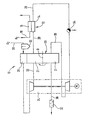
- the only figure shows a block diagram of a fuel cell system according to the invention.
- the fuel cell system 10 shown in the figure includes a fuel cell 12 with a cathode 14 and an anode 16.
- a fuel cell 12 with a cathode 14 and an anode 16.
- anode 16 For better clarity of presentation is in the Figure shows only one fuel cell 12 - in practice it is one by stacking several Fuel cell formed fuel cell block.
- the anode 16 of the fuel cell 12 is supplied with hydrogen H 2 or a hydrogen-containing gas (reformate) via a line 18.
- the cathode 14 of the fuel cell 12 is supplied with intake air containing oxygen O 2 via a line 20.
- the intake air passes through an air filter 22 and a compressor of a compressor expander unit 24 before it is fed to the cathode 14 of the fuel cell 12.
- the fuel cell system 10 further includes one rotatable adsorber 28 (rotor adsorber) arranged in this way is that it has a section in the supply air flow 20 and with another section in an exhaust air stream 30 the Fuel cell 12 is located.
- the axis of rotation D of the rotor adsorber is such between supply air flow 20 and exhaust air flow 30 arranged that when the rotor adsorber 28 rotates in the sense of drawn arrow is always a section of the Rotor adsorbers 28 in the supply air flow 20 and another Section in the exhaust air stream 30 is located. This will be a Desorption area 21 in the supply air flow and an adsorption area 31 defined in the exhaust air stream 30.
- the exhaust air from the cathode 14 of the fuel cell 12 is along a line 30 through an expander of the compressor-expander unit 24 the adsorption area 31 of the rotor adsorber 28 and then fed to a silencer 32.
- a silencer 32 In the exhaust pipe 30 can, as shown in the figure, one of the compressor expander unit 24 upstream condensate drain 34 be provided, which is already the part of the exhaust air in the cathode separates moisture contained in the form of mist droplets. Likewise, one can immediately before the adsorber enters Condensate drain can be arranged.
- the condensate drain 34 can also serve to part of the to recycle the recycled water content liquid because due to the increased humidity of the supply air in front of the cathode 14 of the fuel cell 12 the proportion of in the form of Mist droplets contained moisture will be greater.
- additional condensate drain with or without additional Heat exchanger (cooler) in front of or behind the fuel cell 12 conceivable.
- the remaining moisture in the exhaust air is in the Adsorption region 31 of the rotor adsorber 28 adsorbed.
- the adsorbed water is rotated in the sense of drawn arrow in the desorption region 21 of the Rotoradsorbers 28 rotated and there by no closer energy supply shown, for example in the form of Hot air, desorbed and directly into the supply air flow 20 Humidification of the supply air added.
- the Adsorption of water from the exhaust air flow from the fuel cell at a low pressure level immediately before leaving the Fuel cell system 10.
- the Adsorption also take place before the expander.
- a The fuel cell system according to the invention is desorbed with the help of after passing through the air compressor Compressor expander unit heated supply air flow before Entry into the cathode compartment of the fuel cell.
- desorption by the supply air flow also take place in front of the compressor.
- the serving as adsorbent Solid introduced into the rotor adsorber can, as in the illustrated embodiment possible after the desorption cooled by the intake air in a cooling unit 26 are rotated before it is again in the adsorption region 31 becomes.
- suitable absorbents for use in a Fuel cell systems according to the invention are in particular Silica gel and hydrophilic zeolites are suitable, but also other solids with a large inner surface are usable.
- the adsorbents can be in one Particle bed as well as in the form of ordered structures (Monolith structures, wikkeladsorber) can be used. in the the latter case is an application of the adsorbent to a Carrier material or a use of the homogeneous substance possible in one piece.
- the heat capacity of the solid in particular Adsorbent can be compared to its sorption capacity Add an inert substance so that a energy-optimized desorption through heat recovery good adsorption and desorption is achieved at the same time.
- the Adding the inert substance can take the form of a separate Layer or by mixing with the adsorbent.
- the invention is not based on the illustrated embodiment with a rotor adsorber limited. Rather, it is also designed as a fixed bed adsorption system possible one or more fixed beds includes, to which the supply or exhaust air flow each cyclically can be switched.
- the inventive Fuel cell system can recover water in the Fuel cell system in the sense of a water balance adjustment can be used in a variety of ways.
- it can recovered water in vapor or liquid at least partly for steam reforming gaseous or liquid Energy source, for high or low temperature shift reaction gaseous or liquid energy source or for autothermal Reforming gaseous or liquid energy sources be used.
- DMFC systems Use as make-up water for the liquid energy source Methanol-water mixture possible.
Abstract
Gemäß der Erfindung erfolgt in einem Brennstoffzellensystem mit mindestens einer Brennstoffzelle eine Rückgewinnung von in einem Abluftstrom der mindestens einen Brennstoffzelle enthaltener Feuchtigkeit mittels Adsorption, anschließender Desorption adsorbierten Wassers und Rückführung in den Zuluftstrom und/oder den Brennstoffstrom der mindestens einen Brennstoffzelle und/oder zur Reformereinheit und/oder zur Ergänzung des flüssigen Energieträgers Methanol-Wasser-Gemisch eines DMFC-Systems. <IMAGE>According to the invention, in a fuel cell system with at least one fuel cell, moisture contained in an exhaust air stream of the at least one fuel cell is recovered by means of adsorption, subsequent desorption and return to the supply air stream and / or the fuel stream of the at least one fuel cell and / or to the reformer unit and / or to supplement the liquid energy source methanol-water mixture of a DMFC system. <IMAGE>
Description
Die vorliegende Erfindung betrifft ein Verfahren zum Betrieb eines Brennstoffzellensystems sowie ein Brennstoffzellensystem.The present invention relates to a method of operation a fuel cell system and a fuel cell system.
Bei der Stromerzeugung mittels Brennstoffzellen, insbesondere sogenannten PEM (Polymermembran)-Brennstoffzellen wird der Brennstoffzelle bzw. einem aus einer Mehrzahl übereinander gestapelter Brennstoffzellen gebildeter Brennstoffzellenblock (Stack) Wasserstoff bzw. ein wasserstoffhaltiges Gas und Luft bzw. reiner Sauerstoff zugeführt. Um ein Austrocknen der Membran zu verhindern, wird der Luftstrom und/oder der Brennstoffstrom vor Eintritt in die Brennstoffzelle befeuchtet, wobei das Befeuchtungswasser hierzu dem Kühlkreislauf oder einem separaten Zwischenspeicher entnommen werden kann. Bei der Reaktion von Wasserstoff mit dem Sauerstoff der Luft fällt als Produkt Wasser an, das mit dem Abgasstrom aus dem Brennstoffzellenblock ausgetragen wird. Das in dem Abgasstrom enthaltene Wasser kann anschließend teilweise aus dem Abgasstrom auskondensiert und dem Kühlkreislauf bzw. dem separaten Zwischenspeicher wieder zugeführt werden.When generating electricity using fuel cells, in particular so-called PEM (polymer membrane) fuel cells Fuel cell or one of a plurality one above the other stacked fuel cell formed fuel cell block (Stack) hydrogen or a hydrogen-containing gas and air or pure oxygen supplied. To dry out the Preventing the membrane is the airflow and / or the Humidified fuel flow before entering the fuel cell, the dampening water to the cooling circuit or can be taken from a separate buffer. In the Reaction of hydrogen with the oxygen in the air falls as Product water that with the exhaust gas stream from the Fuel cell block is discharged. That in the exhaust stream contained water can then partially from the Exhaust gas flow condensed and the cooling circuit or separate buffers can be fed again.
Bei der Direkt-Methanol-Brennstoffzelle (DMFC) dient anstelle des Wasserstoffs ein Methanol-Wasser-Gemisch als flüssiger Energieträger. Auch hier wird ein Teil des Wassers über die Membran transportiert und mit dem Luftstrom aus der Brennstoffzelle ausgetragen, so daß ein Zusatz von Wasser zum Methanol-Wasser-Kreislauf nötig ist, wobei das Wasser vorteilhaft in flüssiger Form aus dem Abluftstrom rückgewonnen werden kann. With the direct methanol fuel cell (DMFC) serves instead the hydrogen is a methanol-water mixture as a liquid Energy source. Here too, part of the water flows over the Transported membrane and with the air flow from the Fuel cell discharged, so that an addition of water to the Methanol-water cycle is necessary, taking the water advantageously recovered in liquid form from the exhaust air stream can be.
Aus der US-PS 5,360,679 ist ein Brennstoffzellensystem bekannt, bei dem in dem Brennstoffzellenblock erzeugtes Wasser wiederverwertet wird. Das wiederverwertete Wasser dient zum Kühlen des Brennstoffzellenblocks und zur Befeuchtung sowohl des Brennstoff- als auch des Luftstroms vor deren Einspeisung in den Brennstoffzellenblock. Dazu umfaßt das bekannte Brennstoffzellensystem ein Wasserrückgewinnungs-Teilsystem, in dem das in dem Abgasstrom des Brennstoffzellenblocks enthaltene Wasser mittels Wasserabscheidern zurückgewonnen und einer weiteren Verwendung, beispielsweise einer Speicherung in einem Wasserspeicher und der Befeuchtung des dem Brennstoffzellenblock zugeleiteten Luftstromes, zugeführt. Die in dem bekannten Brennstoffzellensystem Verwendung findenden Wasserabscheider scheiden mechanisch, beispielsweise durch Umlenkung oder Fliehkraft, in dem Luftstrom enthaltene Wassertröpfchen aus. Zur zusätzlichen Teil-Rückgewinnung von im Abluftstrom enthaltenem Wasserdampf werden Wasserkondensatoren eingesetzt, in denen durch Abkühlung des Abgasstroms ein Teil des enthaltenen Wasserdampfes auskondensiert und ebenfalls mit mechanischen Abscheidern abgetrennt wird.A fuel cell system is known from US Pat. No. 5,360,679. in the water generated in the fuel cell block is recycled. The recycled water is used for Cooling the fuel cell block and humidifying both the fuel and air flow before they are fed in the fuel cell block. To do this includes the known Fuel cell system a water recovery subsystem, in which contained in the exhaust gas stream of the fuel cell block Water recovered using water separators and one further use, for example storage in a Water storage and humidification of the Airflow supplied to the fuel cell block. The find use in the known fuel cell system Water separators separate mechanically, for example Deflection or centrifugal force contained in the air flow Water droplets. For additional partial recovery of im Water vapor contained in the exhaust air stream becomes water condensers used in which a part by cooling the exhaust gas flow the water vapor contained condensed and also with mechanical separators is separated.
Bei einem Betrieb einer PEM-Brennstoffzelle mit reinem Wasserstoff verläßt in der Bilanz weniger Wasser das Gesamtsystem (mit dem Abgasstrom) als Wasser in dem System erzeugt wird. Wird der benötigte Wasserstoff intern durch die Reformierung flüssiger Energieträger wie beispielsweise Methanol, Benzin oder Diesel erzeugt, so wird für die Reformierung in der Regel zusätzlich Wasser benötigt. Dies kann dazu führen, daß in der Bilanz mehr Wasser verbraucht bzw. aus dem System ausgetragen wird, als im Gesamtsystem durch die Reaktion erzeugt und im Zwischenspeicher gespeichert wird. Wie bereits erläutert, ist grundsätzlich eine Rückgewinnung des im Abgasstrom enthaltenen Wassers durch Auskondensation möglich, wobei jedoch beim Einsatz in mobilen Systemen, insbesondere im Antrieb von Kraftfahrzeugen, durch das zur Verfügung stehende Temperaturniveau des Fahrzeugkühlers Grenzen gesteckt sind. Auf der anderen Seite sind gerade beim Einsatz in mobilen Systemen zur Vermeidung von Nachtanken und Speichern von Wasser hohe Anforderungen an eine ausgeglichene Wasserbilanz zu stellen.When operating a PEM fuel cell with pure Hydrogen leaves less water in the balance Entire system (with the exhaust gas flow) as water in the system is produced. Is the required hydrogen internally by the Reforming liquid energy sources such as Methanol, petrol or diesel is produced for the Reforming usually requires additional water. This can lead to the fact that more water is consumed in or out of the balance sheet is carried out in the system than in the overall system by the Reaction is generated and stored in the buffer. How already explained, is basically a recovery of the im Water contained in the exhaust gas stream is possible through condensation, however, when used in mobile systems, especially in Drive motor vehicles through the available Temperature levels of the vehicle radiator limits are set. On on the other hand, they are particularly useful in mobile systems to avoid refueling and storing water high To make demands on a balanced water balance.
Ausgehend von diesem Stand der Technik liegt der Erfindung die Aufgabe zugrunde, ein Verfahren zum Betrieb eines Brennstoffzellensystems sowie ein Brennstoffzellensystem bereitzustellen, mit dem bzw. bei dem mit möglichst einfachen und kompakt ausführbaren Mitteln eine möglichst effiziente Rückgewinnung von Wasser aus dem Abgasstrom eines Brennstoffzellenblocks zur Erzielung einer ausgeglichenen Wasserbilanz erreichbar ist.Based on this prior art, the invention lies Task, a method for operating a Fuel cell system and a fuel cell system to provide with or with the simplest possible and compactly executable means as efficient as possible Recovery of water from an exhaust gas stream Fuel cell blocks to achieve a balanced Water balance is achievable.
Zur Lösung dieser Aufgabe wird zum einen ein Verfahren mit den Merkmalen des Anspruches 1, zum anderen ein Brennstoffzellensystem mit den Merkmalen des Anspruches 8 vorgeschlagen.On the one hand, a method with the Features of claim 1, on the other Fuel cell system with the features of claim 8 suggested.
Demnach erfolgt in einem Brennstoffzellensystem mit mindestens einer Brennstoffzelle eine Rückgewinnung von in einem Abluftstrom der mindestens einen Brennstoffzelle enthaltener Feuchtigkeit mittels Adsorption, anschließender Desorption adsorbierten Wassers und Rückführung in den Zuluftstrom und/oder den Brennstoffstrom oder in den Flüssigkeitsstrom der Anodenseite und/oder in dem Kühlwasserkreislauf der mindestens einen Brennstoffzelle. Durch die Anwendung von Adsorptionstechnik zur Extraktion von Feuchtigkeit aus dem Abluftstrom der mindestens einen Brennstoffzelle wird mit relativ geringem Aufwand im Vergleich zu den bekannten Techniken ein hoher Anteil des als Feuchtigkeit im Abluftstrom enthaltenen Wassers zurückgewonnen. Insbesondere gestattet die Anwendung der Adsorptionstechnik kompakte Abmessungen, wodurch die Einsatzmöglichkeiten eines Brennstoffzellensystems im mobilen Bereich verbessert werden. Das adsorbierte Wasser wird anschließend durch Energiebeaufschlagung desorbiert und weiterverwendet. Zur Energiebeaufschlagung kann beispielsweise Heißgas, ein flüssiger Wärmeträger, elektrische Beheizung oder elektromagnetische Strahlung eingesetzt werden. Das zurückgewonnene Wasser kann zur weiteren Verwendung vorzugsweise zur Befeuchtung des für die Reaktion in der Brennstoffzelle bestimmten Zuluftstroms zur Brennstoffzelle zurückgeführt werden, wobei vor der Rückführung zum Zuluftstrom beispielsweise eine Zwischenspeicherung in einem dafür vorgesehenen Wassertank erfolgen kann. Das zurückgewonnene Wasser kann auch dem Brennstoffzustrom zurückgeführt werden oder, bei einer vorgeschalteten Reformierungsstufe, der Reformereinheit zugeführt werden. Darüber hinaus kann das Wasser bei DMFC-Systemen zur Ergänzung des flüssigen Methanol-Wasser-Gemischs Verwendung finden.Accordingly, in a fuel cell system, at least a recovery of a fuel cell in one Exhaust air flow containing at least one fuel cell Moisture by means of adsorption, followed by desorption adsorbed water and return to the supply air flow and / or the fuel flow or in the liquid flow Anode side and / or in the cooling water circuit of at least a fuel cell. By using Adsorption technology for extracting moisture from the Exhaust air flow of the at least one fuel cell is included relatively little effort compared to the known Techniques a high percentage of that as moisture in the exhaust air stream contained water recovered. In particular, the Application of the adsorption technology compact dimensions, whereby the possible uses of a fuel cell system in mobile area can be improved. The adsorbed water will then desorbed by applying energy and further used. For example, to apply energy Hot gas, a liquid heat transfer medium, electrical heating or electromagnetic radiation can be used. The Recovered water can be used again preferably for moistening the for the reaction in the Fuel cell certain supply air flow to the fuel cell be returned, before returning to the supply air flow for example a buffer in one for that provided water tank can be done. The recovered Water can also be returned to the fuel inflow or, at an upstream reform stage, the Reformer unit are fed. In addition, that can Water in DMFC systems to supplement the liquid methanol-water mixture Find use.
Vorteilhafte Ausgestaltungen der Erfindung ergeben sich aus den Unteransprüchen.Advantageous embodiments of the invention result from the Subclaims.
In besonders vorteilhafter Ausgestaltung der Erfindung erfolgt die Adsorption mittels eines Adsorbens, das auf einem kontinuierlich oder getaktet rotierenden Träger angeordnet ist. Durch diese rotierende Anordnung (Rotoradsorber) kann jeweils ein Abschnitt des beispielsweise scheibenförmig oder zylinderförmig ausgebildeten drehbaren Trägers in den Abluftstrom gebracht werden und dort Feuchtigkeit aus dem Abluftstrom adsorbieren. Durch die Rotation des Trägers wird der im Abluftstrom befindliche Abschnitt dann aus dem Abluftstrom weggedreht und in einen Desorptionsbereich hineingedreht, in welchem durch Zufuhr von Energie, beispielsweise in der Form von Heißluft oder dergleichen, das adsorbierte Wasser wieder desorbiert wird. Um für die anschließende Adsorption günstige Ausgangsbedingungen zu schaffen, kann das Adsorbens nach der Desorption zusätzlich gekühlt werden. Die Dreh- bzw. Taktzahl des Rotoradsorbers wird dabei insbesondere dem jeweiligen Lastzustand angepaßt.In a particularly advantageous embodiment of the invention the adsorption by means of an adsorbent, which is on a continuously or clocked rotating carrier is arranged. This rotating arrangement (rotor adsorber) can in each case a section of, for example, disc-shaped or cylindrical rotatable carrier in the Exhaust air flow are brought and there moisture from the Adsorb exhaust air flow. Due to the rotation of the carrier the section in the exhaust air flow then from the Exhaust air flow turned away and into a desorption area screwed in, in which by supplying energy, for example in the form of hot air or the like adsorbed water is desorbed again. To for the subsequent adsorption to favorable starting conditions create the adsorbent after desorption be cooled. The speed or cycle number of the rotor adsorber is adapted in particular to the respective load condition.
In alternativer Ausgestaltung der Erfindung erfolgt die Adsorption bzw. Desorption in einen oder mehreren Festbetten, deren Zu- und Abluftströme zyklisch umgeschaltet werden. In dieser Ausgestaltung wird somit nicht das Absorbens abwechselnd in den Adsorptions- bzw. den Desorptionsbereich gedreht, sondern die Zuluft- und Abluftströme werden abwechselnd auf das bzw. die Festbetten umgeleitet. Durch diese Maßnahme kann die Desorption auf einfache Weise durch indirekte Wärmezufuhr, beispielsweise aus dem Kühlkreislauf des Brennstoffzellensystems oder durch elektrische Heizung, unterstützt werden.In an alternative embodiment of the invention, the Adsorption or desorption in one or more fixed beds, whose supply and exhaust air flows are switched cyclically. In this configuration therefore does not alternate the absorbent rotated into the adsorption or desorption area, but the supply air and exhaust air flows are alternately on the or redirected the fixed beds. Through this measure, the Desorption in a simple way through indirect heat supply, for example from the cooling circuit of the Fuel cell system or by electric heating, get supported.
Die vorliegende Erfindung eignet sich insbesondere zur Anwendung in Brennstoffzellensystemen aus PEM-Brennstoffzellen sowohl beim Betrieb mit Wasserstoff oder Reformat als auch mit flüssigen Energieträgern (DMFC), wobei auch eine Kombination aus Kondensation und Adsorption möglich ist. Sie ist jedoch nicht auf PEM-Brennstoffzellensysteme beschränkt.The present invention is particularly suitable for Application in fuel cell systems made of PEM fuel cells both when operating with hydrogen or reformate as well as with liquid energy sources (DMFC), including a combination from condensation and adsorption is possible. However, it is not limited to PEM fuel cell systems.
Die Erfindung ist anhand eines Ausführungsbeispieles in der Zeichnung dargestellt und wird im folgenden unter Bezugnahme auf die Zeichnung näher erläutert.The invention is based on an embodiment in the Drawing and is shown below with reference explained in more detail on the drawing.
Die einzige Figur zeigt ein Blockschaltbild eines erfindungsgemäßen Brennstoffzellensystems.The only figure shows a block diagram of a fuel cell system according to the invention.
Das in der Figur dargestellte Brennstoffzellensystem 10 umfaßt
eine Brennstoffzelle 12 mit einer Kathode 14 und einer Anode
16. Zur besseren Übersichtlichkeit der Darstellung ist in der
Figur nur eine Brennstoffzelle 12 eingezeichnet - in der Praxis
handelt es sich dahingegen um einen durch Stapelung mehrerer
Brennstoffzellen gebildeten Brennstoffzellenblock.The
Der Anode 16 der Brennstoffzelle 12 wird über eine Leitung 18
Wasserstoff H2 oder ein wasserstoffhaltiges Gas (Reformat)
zugeführt. Der Kathode 14 der Brennstoffzelle 12 wird über eine
Leitung 20 Sauerstoff O2 enthaltende Ansaugluft zugeführt. Die
Ansaugluft durchläuft einen Luftfilter 22 und einen Kompressor
einer Kompressor-Expander-Einheit 24, bevor sie der Kathode 14
der Brennstoffzelle 12 zugeführt wird. The
Das Brennstoffzellensystem 10 umfaßt des weiteren einen
drehbaren Adsorber 28 (Rotoradsorber), der derart angeordnet
ist, daß er mit einem Abschnitt in dem Zuluftstrom 20 und mit
einem anderen Abschnitt in einem Abluftstrom 30 der
Brennstoffzelle 12 liegt. Die Drehachse D des Rotoradsorbers
ist derart zwischen Zuluftstrom 20 und Abluftstrom 30
angeordnet, daß bei Drehung des Rotoradsorbers 28 im Sinne des
eingezeichneten Pfeiles sich stets ein Abschnitt des
Rotoradsorbers 28 in dem Zuluftstrom 20 und ein anderer
Abschnitt in dem Abluftstrom 30 befindet. Dadurch werden ein
Desorptionsbereich 21 im Zuluftstrom und ein Adsorptionsbereich
31 im Abluftstrom 30 definiert.The
Die Abluft der Kathode 14 der Brennstoffzelle 12 wird entlang
einer Leitung 30 durch einen Expander der Kompressor-Expander-Einheit
24 dem Adsorptionsbereich 31 des Rotoradsorbers 28 und
danach einem Schalldämpfer 32 zugeführt. In der Abluftleitung
30 kann, wie in der Figur dargestellt, ein der Kompressor-Expander-Einheit
24 vorgeordneter Kondensat-Ableiter 34
vorgesehen sein, der bereits den Teil der in der Kathodenabluft
in Form von Nebeltröpfchen enthaltenen Feuchtigkeit abscheidet.
Ebenso kann auch unmittelbar vor dem Adsorbereintritt ein
Kondensat-Ableiter angeordnet sein.The exhaust air from the
Der Kondensat-Ableiter 34 kann auch dazu dienen, einen Teil des
rückgeführten Wasseranteils flüssig zurückzugewinnen, weil
durch die erhöhte Feuchtigkeit der Zuluft vor der Kathode 14
der Brennstoffzelle 12 der Anteil der in Form von
Nebeltröpfchen enthaltenen Feuchtigkeit größer sein wird.
Ebenso ist zur flüssigen Rückgewinnung die Verwendung eines
weiteren Kondensat-Ableiters mit oder ohne zusätzlichen
Wärmetauscher (Kühler) vor oder hinter der Brennstoffzelle 12
denkbar.The
Die verbleibende Feuchtigkeit in der Abluft wird in dem
Adsorptionsbereich 31 des Rotoradsorbers 28 adsorbiert. Das
adsorbierte Wasser wird durch Drehung im Sinne des
eingezeichneten Pfeiles in den Desorptionsbereich 21 des
Rotoradsorbers 28 gedreht und dort durch nicht näher
dargestellte Energiezufuhr, beispielsweise in Form von
Heißluft, desorbiert und direkt in den Zuluftstrom 20 zur
Befeuchtung der Zuluft aufgenommen. Somit erfolgt die
Adsorption des Wassers aus dem Abluftstrom der Brennstoffzelle
auf niedrigem Druckniveau unmittelbar vor dem Verlassen des
Brennstoffzellensystems 10. Selbstverständlich kann die
Adsorption auch vor dem Expander erfolgen.The remaining moisture in the exhaust air is in the
In dem in der Figur dargestellten Ausführungsbeispiel eines
erfindungsgemäßen Brennstoffzellensystem erfolgt die Desorption
mit Hilfe des nach dem Durchtritt durch den Luftkompressor der
Kompressor-Expander-Einheit erhitzten Zuluftstroms vor dem
Eintritt in den Kathodenraum der Brennstoffzelle. Somit wird
als Trägergasstrom für die Desorption erfindungsgemäß der
Zuluftstrom zur Brennstoffzelle auf hohem Druckniveau
unmittelbar vor Eintritt in die Brennstoffzelle 12 verwendet.
Alternativ hierzu kann eine Desorption durch den Zuluftstrom
auch vor dem Kompressor erfolgen. Der als Adsorbens dienende,
in dem Rotoradsorber eingebrachte Feststoff kann, wie in dem
dargestellten Ausführungsbeispiel möglich, nach der Desorption
in einer Kühlungseinheit 26 durch die Ansaugluft gekühlt
werden, bevor er wieder in den Adsorptionsbereich 31 gedreht
wird.In the embodiment shown in the figure, a
The fuel cell system according to the invention is desorbed
with the help of after passing through the air compressor
Compressor expander unit heated supply air flow before
Entry into the cathode compartment of the fuel cell. Thus
as a carrier gas stream for desorption according to the invention
Supply air flow to the fuel cell at a high pressure level
used immediately before entering the
Als geeignete Absorbentien zur Verwendung in einem erfindungsgemäßen Brennstoffzellensystem sind insbesondere Silikagel und hydrophile Zeolithe geeignet, wobei jedoch auch andere Feststoffe mit einer großen inneren Oberfläche verwendbar sind. Die Adsorbentien können sowohl in einer Partikelschüttung als auch in Form geordneter Strukturen (Monolithstrukturen, Wikkeladsorber) verwendet werden. Im letzteren Falle ist eine Aufbringung des Adsorbens auf ein Trägermaterial oder auch eine Verwendung des homogenen Stoffes in einstückiger Form möglich. As suitable absorbents for use in a Fuel cell systems according to the invention are in particular Silica gel and hydrophilic zeolites are suitable, but also other solids with a large inner surface are usable. The adsorbents can be in one Particle bed as well as in the form of ordered structures (Monolith structures, wikkeladsorber) can be used. in the the latter case is an application of the adsorbent to a Carrier material or a use of the homogeneous substance possible in one piece.
Die Wärmekapazität des insbesondere als Feststoff vorliegenden Adsorbens kann im Vergleich zu seiner Sorptionskapazität durch Hinzufügen eines Inertstoffes so eingestellt werden, daß eine energieoptimierte Desorption durch Wärmerückgewinnung bei gleichzeitig guter Adsorption und Desorption erreicht wird. Das Hinzufügen des Inertstoffes kann sowohl in Form einer separaten Schicht oder durch Mischung mit dem Adsorbens erfolgen.The heat capacity of the solid in particular Adsorbent can be compared to its sorption capacity Add an inert substance so that a energy-optimized desorption through heat recovery good adsorption and desorption is achieved at the same time. The Adding the inert substance can take the form of a separate Layer or by mixing with the adsorbent.
Wie bereits vorstehend ausgeführt, ist die Erfindung nicht auf das dargestellte Ausführungsbeispiel mit einem Rotoradsorber beschränkt. Vielmehr ist auch eine Ausführung als Festbettadsorptionsanlage möglich, die ein oder mehrere Festbetten umfaßt, auf die der Zu- bzw. der Abluftstrom jeweils zyklisch umgeschaltet werden.As already stated above, the invention is not based on the illustrated embodiment with a rotor adsorber limited. Rather, it is also designed as a fixed bed adsorption system possible one or more fixed beds includes, to which the supply or exhaust air flow each cyclically can be switched.
Mit dem erfindungsgemäßen Verfahren bzw. dem erfindungsgemäßen Brennstoffzellensystem rückgewonnenes Wasser kann in dem Brennstoffzellensystem im Sinne einer Wasserbilanzausgleichung vielfältig eingesetzt werden. Insbesondere kann das rückgewonnene Wasser dampfförmig oder flüssig wenigstens teilweise zur Dampfreformierung gasförmiger oder flüssiger Energieträger, zur Hoch- oder Niedertemperatur-Shift-Reaktion gasförmiger oder flüssiger Energieträger oder zur autothermen Reformierung gasförmiger oder flüssiger Energieträger eingesetzt werden. Darüber hinaus ist bei DMFC-Systemen der Einsatz als Ergänzungswasser für den flüssigen Energieträger Methanol-Wasser-Gemisch möglich.With the inventive method or the inventive Fuel cell system can recover water in the Fuel cell system in the sense of a water balance adjustment can be used in a variety of ways. In particular, it can recovered water in vapor or liquid at least partly for steam reforming gaseous or liquid Energy source, for high or low temperature shift reaction gaseous or liquid energy source or for autothermal Reforming gaseous or liquid energy sources be used. In addition, with DMFC systems Use as make-up water for the liquid energy source Methanol-water mixture possible.
Claims (18)
dadurch gekennzeichnet,
daß in einem Abluftstrom (30) der mindestens einen Brennstoffzelle (12) enthaltene Feuchtigkeit mittels Adsorption (31) dem Abluftstrom (30) entzogen, das adsorbierte Wasser desorbiert (21) und in den Zuluftstrom (20) und/oder den Brennstoffstrom und/oder in den Flüssigkeitsstrom der Anodenseite und/oder in den Kühlwasserkreislauf der mindestens einen Brennstoffzelle (12) zurückgeführt wird.Method for operating a fuel cell system which comprises at least one fuel cell (12),
characterized by
that in an exhaust air stream (30) the at least one fuel cell (12) contained moisture by means of adsorption (31) from the exhaust air stream (30), the adsorbed water desorbed (21) and in the supply air stream (20) and / or the fuel stream and / or is fed back into the liquid flow on the anode side and / or into the cooling water circuit of the at least one fuel cell (12).
Applications Claiming Priority (2)
| Application Number | Priority Date | Filing Date | Title |
|---|---|---|---|
| DE19902219A DE19902219C1 (en) | 1999-01-21 | 1999-01-21 | Process for operating a fuel cell system comprises removing moisture from a waste air stream of a fuel cell, desorbing the water and recycling |
| DE19902219 | 1999-01-21 |
Publications (3)
| Publication Number | Publication Date |
|---|---|
| EP1022796A2 true EP1022796A2 (en) | 2000-07-26 |
| EP1022796A3 EP1022796A3 (en) | 2004-07-28 |
| EP1022796B1 EP1022796B1 (en) | 2006-06-21 |
Family
ID=7894907
Family Applications (1)
| Application Number | Title | Priority Date | Filing Date |
|---|---|---|---|
| EP99122279A Expired - Lifetime EP1022796B1 (en) | 1999-01-21 | 1999-11-09 | Method for the operation of a fuel cell system and fuel cell system |
Country Status (2)
| Country | Link |
|---|---|
| EP (1) | EP1022796B1 (en) |
| DE (2) | DE19902219C1 (en) |
Cited By (4)
| Publication number | Priority date | Publication date | Assignee | Title |
|---|---|---|---|---|
| WO2000063990A2 (en) * | 1999-04-19 | 2000-10-26 | Mannesmann Ag | Device and method for humidifying a fuel cell membrane and fuel cell |
| EP1099269A2 (en) * | 1998-06-03 | 2001-05-16 | International Fuel Cells Corporation | Direct mass and heat transfer fuel cell power plant |
| DE102008007024A1 (en) | 2008-01-31 | 2009-08-06 | Fraunhofer-Gesellschaft zur Förderung der angewandten Forschung e.V. | Fuel cell system with adsorption heat storage |
| KR101117633B1 (en) | 2004-06-30 | 2012-02-29 | 삼성에스디아이 주식회사 | Carbon monoxide adsorbent for fuel cell, carbon monoxide remover for fuel cell, fuel cell system, and removal method using the carbon monoxide adsorbent |
Families Citing this family (10)
| Publication number | Priority date | Publication date | Assignee | Title |
|---|---|---|---|---|
| US6485854B1 (en) * | 2000-10-19 | 2002-11-26 | General Motors Corporation | Gas-liquid separator for fuel cell system |
| DE10065306A1 (en) * | 2000-12-29 | 2002-07-18 | Siemens Ag | Method for operating a fuel cell system that can be used in a vehicle and associated fuel cell system |
| US6727016B2 (en) * | 2001-08-09 | 2004-04-27 | Motorola, Inc. | Direct methanol fuel cell including a water recovery and re-circulation system and method of fabrication |
| DE10212872A1 (en) * | 2002-03-22 | 2003-10-02 | Volkswagen Ag | Adjustable cooling of a flow of an operating substance in a heat exchanger, especially for vehicle fuel cell system, uses a flow of cooling substance with a temperature lower in relation to the flow of the operating substance |
| US7018732B2 (en) | 2002-04-15 | 2006-03-28 | Hydrogenics Corporation | System and method for management of gas and water in fuel cell system |
| DE10230283A1 (en) | 2002-07-05 | 2004-01-29 | Daimlerchrysler Ag | Method and arrangement for cleaning the gases to be supplied to a fuel cell for operation of components that are unfavorable for the fuel cell operation |
| EP1543576A2 (en) * | 2002-09-23 | 2005-06-22 | Hydrogenics Corporation | System and method for management of gas and water in fuel cell system |
| JP2004342372A (en) * | 2003-05-13 | 2004-12-02 | Toyota Motor Corp | Fuel cell system and vehicle loading the same |
| DE102009010594A1 (en) * | 2009-02-25 | 2010-08-26 | Enymotion Gmbh | Fuel cell system has fuel cell and process gas generating device for generation of process gas for operating fuel cell |
| DE102016213836A1 (en) * | 2016-07-27 | 2018-02-01 | Bayerische Motoren Werke Aktiengesellschaft | Method for heating a water separator and water separator for a fuel cell system of a motor vehicle |
Citations (3)
| Publication number | Priority date | Publication date | Assignee | Title |
|---|---|---|---|---|
| WO1999005741A1 (en) * | 1997-07-25 | 1999-02-04 | Emprise Corporation | Fuel cell gas management system |
| WO1999028985A1 (en) * | 1997-12-01 | 1999-06-10 | Ballard Power Systems Inc. | Method and apparatus for distributing water to an ion-exchange membrane in a fuel cell |
| WO1999067830A1 (en) * | 1998-06-24 | 1999-12-29 | International Fuel Cells Corporation | Mass and heat recovery system for a fuel cell power plant |
Family Cites Families (3)
| Publication number | Priority date | Publication date | Assignee | Title |
|---|---|---|---|---|
| US5250368A (en) * | 1992-11-19 | 1993-10-05 | Ergenics, Inc. | Extended cycle-life metal hydride battery for electric vehicles |
| US5360679A (en) * | 1993-08-20 | 1994-11-01 | Ballard Power Systems Inc. | Hydrocarbon fueled solid polymer fuel cell electric power generation system |
| DE19704888A1 (en) * | 1997-02-10 | 1998-08-13 | Bhf Verfahrenstechnik Gmbh | Process for operating a boiler with condensing boiler use and boiler to implement the process |
-
1999
- 1999-01-21 DE DE19902219A patent/DE19902219C1/en not_active Expired - Fee Related
- 1999-11-09 DE DE59913594T patent/DE59913594D1/en not_active Expired - Lifetime
- 1999-11-09 EP EP99122279A patent/EP1022796B1/en not_active Expired - Lifetime
Patent Citations (3)
| Publication number | Priority date | Publication date | Assignee | Title |
|---|---|---|---|---|
| WO1999005741A1 (en) * | 1997-07-25 | 1999-02-04 | Emprise Corporation | Fuel cell gas management system |
| WO1999028985A1 (en) * | 1997-12-01 | 1999-06-10 | Ballard Power Systems Inc. | Method and apparatus for distributing water to an ion-exchange membrane in a fuel cell |
| WO1999067830A1 (en) * | 1998-06-24 | 1999-12-29 | International Fuel Cells Corporation | Mass and heat recovery system for a fuel cell power plant |
Non-Patent Citations (1)
| Title |
|---|
| PERRY, R., GREEN, D.: "Perry's Chemical Engineers' Handbook" 1984, MCGRAW-HILL BOOK COMPANY , SINGAPORE , XP002281202 * Seiten 16-45 - Seiten 16-48 * * Seiten 19-45 - Seiten 19-48 * * |
Cited By (6)
| Publication number | Priority date | Publication date | Assignee | Title |
|---|---|---|---|---|
| EP1099269A2 (en) * | 1998-06-03 | 2001-05-16 | International Fuel Cells Corporation | Direct mass and heat transfer fuel cell power plant |
| EP1099269A4 (en) * | 1998-06-03 | 2001-09-26 | Int Fuel Cells Corp | Direct mass and heat transfer fuel cell power plant |
| WO2000063990A2 (en) * | 1999-04-19 | 2000-10-26 | Mannesmann Ag | Device and method for humidifying a fuel cell membrane and fuel cell |
| WO2000063990A3 (en) * | 1999-04-19 | 2001-04-05 | Mannesmann Ag | Device and method for humidifying a fuel cell membrane and fuel cell |
| KR101117633B1 (en) | 2004-06-30 | 2012-02-29 | 삼성에스디아이 주식회사 | Carbon monoxide adsorbent for fuel cell, carbon monoxide remover for fuel cell, fuel cell system, and removal method using the carbon monoxide adsorbent |
| DE102008007024A1 (en) | 2008-01-31 | 2009-08-06 | Fraunhofer-Gesellschaft zur Förderung der angewandten Forschung e.V. | Fuel cell system with adsorption heat storage |
Also Published As
| Publication number | Publication date |
|---|---|
| DE59913594D1 (en) | 2006-08-03 |
| EP1022796A3 (en) | 2004-07-28 |
| EP1022796B1 (en) | 2006-06-21 |
| DE19902219C1 (en) | 2000-06-08 |
Similar Documents
| Publication | Publication Date | Title |
|---|---|---|
| DE19902219C1 (en) | Process for operating a fuel cell system comprises removing moisture from a waste air stream of a fuel cell, desorbing the water and recycling | |
| DE19731642C1 (en) | Fuel cell vehicle | |
| DE69931171T2 (en) | POWER GENERATION SYSTEM | |
| DE10204845A1 (en) | Carbon monoxide adsorption for cleaning carbon monoxide in a fuel cell system | |
| DE60222712T2 (en) | Water recovery for a fuel cell plant | |
| DE112017005935T5 (en) | The fuel cell system | |
| DE10102447A1 (en) | Humidifier for use with a fuel cell | |
| DE102011111742A1 (en) | The fuel cell system | |
| WO2001022512A2 (en) | Fuel cell facility and operating method for the same | |
| DE102014100702A1 (en) | The fuel cell system | |
| DE69915632T2 (en) | FUEL CELL PLANT WITH DIRECT MASS AND HEAT TRANSPORT | |
| DE102009051476A1 (en) | Fuel cell system with at least one fuel cell | |
| JP2005533360A (en) | Gas flow humidification apparatus and method | |
| WO2009059571A1 (en) | High-temperature fuel cell system having sectional circuit of the anode waste gas and outward transfer of gas components | |
| DE10034399A1 (en) | Process for operating a fuel cell system, used for an electromotor, recycles water contained in the moist exhaust air stream by removing it by absorption, then releasing it by desorption | |
| DE102004017281B4 (en) | Fuel cell system and use of a fuel cell system in a vehicle | |
| DE19943059B4 (en) | System for condensing a liquid from a gas stream | |
| DE102014211847A1 (en) | The fuel cell system | |
| WO2011020560A1 (en) | Method and device for generating electric energy | |
| DE102008007024A1 (en) | Fuel cell system with adsorption heat storage | |
| DE602004000440T2 (en) | Fuel cell drive unit for a motor vehicle and method for thawing a fuel cell | |
| DE102010041465B4 (en) | Fuel cell system with direct methanol fuel cell and method of operation | |
| DE102009009674A1 (en) | Fuel cell system with at least one fuel cell | |
| DE10232757B4 (en) | Apparatus and method for humidifying a gas flow | |
| DE102019211589A1 (en) | Humidifier, fuel cell device with humidifier and motor vehicle |
Legal Events
| Date | Code | Title | Description |
|---|---|---|---|
| PUAI | Public reference made under article 153(3) epc to a published international application that has entered the european phase |
Free format text: ORIGINAL CODE: 0009012 |
|
| AK | Designated contracting states |
Kind code of ref document: A2 Designated state(s): AT BE CH CY DE DK ES FI FR GB GR IE IT LI LU MC NL PT SE |
|
| AX | Request for extension of the european patent |
Free format text: AL;LT;LV;MK;RO;SI |
|
| PUAL | Search report despatched |
Free format text: ORIGINAL CODE: 0009013 |
|
| AK | Designated contracting states |
Kind code of ref document: A3 Designated state(s): AT BE CH CY DE DK ES FI FR GB GR IE IT LI LU MC NL PT SE |
|
| AX | Request for extension of the european patent |
Extension state: AL LT LV MK RO SI |
|
| 17P | Request for examination filed |
Effective date: 20040816 |
|
| 17Q | First examination report despatched |
Effective date: 20041118 |
|
| AKX | Designation fees paid |
Designated state(s): DE FR GB IT |
|
| GRAP | Despatch of communication of intention to grant a patent |
Free format text: ORIGINAL CODE: EPIDOSNIGR1 |
|
| GRAS | Grant fee paid |
Free format text: ORIGINAL CODE: EPIDOSNIGR3 |
|
| GRAA | (expected) grant |
Free format text: ORIGINAL CODE: 0009210 |
|
| AK | Designated contracting states |
Kind code of ref document: B1 Designated state(s): DE FR GB IT |
|
| PG25 | Lapsed in a contracting state [announced via postgrant information from national office to epo] |
Ref country code: IT Free format text: LAPSE BECAUSE OF FAILURE TO SUBMIT A TRANSLATION OF THE DESCRIPTION OR TO PAY THE FEE WITHIN THE PRESCRIBED TIME-LIMIT;WARNING: LAPSES OF ITALIAN PATENTS WITH EFFECTIVE DATE BEFORE 2007 MAY HAVE OCCURRED AT ANY TIME BEFORE 2007. THE CORRECT EFFECTIVE DATE MAY BE DIFFERENT FROM THE ONE RECORDED. Effective date: 20060621 |
|
| REG | Reference to a national code |
Ref country code: GB Ref legal event code: FG4D Free format text: NOT ENGLISH |
|
| REF | Corresponds to: |
Ref document number: 59913594 Country of ref document: DE Date of ref document: 20060803 Kind code of ref document: P |
|
| GBT | Gb: translation of ep patent filed (gb section 77(6)(a)/1977) |
Effective date: 20060928 |
|
| ET | Fr: translation filed | ||
| PLBE | No opposition filed within time limit |
Free format text: ORIGINAL CODE: 0009261 |
|
| STAA | Information on the status of an ep patent application or granted ep patent |
Free format text: STATUS: NO OPPOSITION FILED WITHIN TIME LIMIT |
|
| RAP2 | Party data changed (patent owner data changed or rights of a patent transferred) |
Owner name: DAIMLERCHRYSLER AG |
|
| 26N | No opposition filed |
Effective date: 20070322 |
|
| REG | Reference to a national code |
Ref country code: FR Ref legal event code: CD |
|
| PGFP | Annual fee paid to national office [announced via postgrant information from national office to epo] |
Ref country code: FR Payment date: 20100603 Year of fee payment: 11 |
|
| PGFP | Annual fee paid to national office [announced via postgrant information from national office to epo] |
Ref country code: DE Payment date: 20100511 Year of fee payment: 11 |
|
| PGFP | Annual fee paid to national office [announced via postgrant information from national office to epo] |
Ref country code: GB Payment date: 20100423 Year of fee payment: 11 |
|
| GBPC | Gb: european patent ceased through non-payment of renewal fee |
Effective date: 20101109 |
|
| REG | Reference to a national code |
Ref country code: DE Ref legal event code: R119 Ref document number: 59913594 Country of ref document: DE Effective date: 20110601 Ref country code: DE Ref legal event code: R119 Ref document number: 59913594 Country of ref document: DE Effective date: 20110531 |
|
| REG | Reference to a national code |
Ref country code: FR Ref legal event code: ST Effective date: 20110801 |
|
| PG25 | Lapsed in a contracting state [announced via postgrant information from national office to epo] |
Ref country code: DE Free format text: LAPSE BECAUSE OF NON-PAYMENT OF DUE FEES Effective date: 20110531 |
|
| PG25 | Lapsed in a contracting state [announced via postgrant information from national office to epo] |
Ref country code: FR Free format text: LAPSE BECAUSE OF NON-PAYMENT OF DUE FEES Effective date: 20101130 |
|
| PG25 | Lapsed in a contracting state [announced via postgrant information from national office to epo] |
Ref country code: GB Free format text: LAPSE BECAUSE OF NON-PAYMENT OF DUE FEES Effective date: 20101109 |