EP1022539A2 - Analog quantity display method, analog quantity measuring method, and digital/analog display type measuring instrument - Google Patents
Analog quantity display method, analog quantity measuring method, and digital/analog display type measuring instrument Download PDFInfo
- Publication number
- EP1022539A2 EP1022539A2 EP00100753A EP00100753A EP1022539A2 EP 1022539 A2 EP1022539 A2 EP 1022539A2 EP 00100753 A EP00100753 A EP 00100753A EP 00100753 A EP00100753 A EP 00100753A EP 1022539 A2 EP1022539 A2 EP 1022539A2
- Authority
- EP
- European Patent Office
- Prior art keywords
- analog
- display
- value
- count value
- tolerance
- Prior art date
- Legal status (The legal status is an assumption and is not a legal conclusion. Google has not performed a legal analysis and makes no representation as to the accuracy of the status listed.)
- Granted
Links
Images




Classifications
-
- G—PHYSICS
- G01—MEASURING; TESTING
- G01B—MEASURING LENGTH, THICKNESS OR SIMILAR LINEAR DIMENSIONS; MEASURING ANGLES; MEASURING AREAS; MEASURING IRREGULARITIES OF SURFACES OR CONTOURS
- G01B3/00—Measuring instruments characterised by the use of mechanical techniques
- G01B3/002—Details
- G01B3/004—Scales; Graduations
-
- G—PHYSICS
- G01—MEASURING; TESTING
- G01D—MEASURING NOT SPECIALLY ADAPTED FOR A SPECIFIC VARIABLE; ARRANGEMENTS FOR MEASURING TWO OR MORE VARIABLES NOT COVERED IN A SINGLE OTHER SUBCLASS; TARIFF METERING APPARATUS; MEASURING OR TESTING NOT OTHERWISE PROVIDED FOR
- G01D7/00—Indicating measured values
- G01D7/002—Indicating measured values giving both analog and numerical indication
Definitions
- the present invention relates to an analog quantity display method for displaying a measured analog quantity such as the size or shape of an object to be measured, an analog quantity measuring method for measuring the analog quantity, and a digital/analog display type measuring instrument for measuring an analog quantity such as the size or shape of an object to be measured.
- digital/analog display type measuring instruments such as dial gauges use a CRT display or a liquid crystal display to display a scale and a pointer as pictures or graphics in order to display results of measurements by analog display.
- the present assignee has proposed a digital/analog display type measuring instrument which allows both digital and analog measurements to be effectively executed even with omission of premeasurements using a gauge block, by Japanese Laid-Open Patent Publication (Kokai) No. 10-132546. That is, the proposed digital/analog display type measuring instrument has a large number of pointer segments arranged along a scale which indicate a measured value, and its characterized by including a switch which can independently switch an analog scale interval (weight per pointer segment), and a switch which can set a reference (zero) point for analog display at an arbitrary position of a probe.
- the proposed digital/analog display type measuring instrument which is used as a dial gauge or the like, displays the present measured value by lighting one of the large number of pointer segments arranged along the scale, thereby requiring the display to be relatively large in area.
- this instrument has a plurality of switches or the like for switching the analog scale interval and setting the reference point for analog display, resulting in a considerably large-sized display section.
- the above conventional digital/analog display type measuring instrument has the disadvantage that if this measuring instrument is designed as a cylinder gauge for operation in a relatively small space, the display section of the gauge body has to be incomparably larger than the probe section. Therefore, this measuring instrument cannot be easily handled.
- an analog quantity display method of counting displacement of a probe disposed in contact with an object to be measured, and analog-displaying a count value obtained by the counting, by an analog display section as an analog quantity comprising the steps of displaying the count value by the analog display section as a bar graph comprising a large number of analog bars arranged in juxtaposition in one direction, and updating an offset provided for the analog-displayed count value in a manner such that a peak value of the count value is displayed within a possible analog-display range of the analog display section, if the peak value exceeds the possible analog-display range.
- the offset is updated in a manner such that the peak value is displayed at a substantially central position of the possible analog-display range of the analog display section.
- the peak value is displayed by flickering at least one corresponding analog bar in the analog display section.
- the peak value is displayed by changing display color of at least one corresponding analog bar in the analog display section.
- the analog quantity display method further includes the step of setting a measuring tolerance and setting the offset in a manner such that a numerical value of the set tolerance is displayed within the possible analog-display range of the analog display section.
- the step of setting the tolerance comprises setting a plurality of tolerance values as the tolerance and setting the offset and a display scale interval of the bar graph in a manner such that the plurality of tolerance values are displayed within the possible analog-display range of the analog display section.
- the step of setting the tolerance comprises setting a tolerance upper limit value and a tolerance lower limit value as the tolerance and setting the offset and a display scale interval of the bar graph in a manner such that the tolerance upper limit value and tolerance lower limit value are displayed symmetrically with respect to a central position of the possible analog-display range.
- the step of setting the tolerance comprises setting the offset and the display scale interval of the bar graph in a manner such that the tolerance upper limit value and tolerance lower limit value are displayed symmetrically with respect to the central position of the possible analog-display range and such that a difference between the tolerance upper limit value and the tolerance lower limit value is substantially half the possible analog-display range.
- the numerical value of the set tolerance is displayed by reversing display state of at least one corresponding analog bar in the analog display section from a lighted state to an extinguished state or vice versa.
- the numerical value of the set tolerance is displayed by changing display color of at lead one corresponding analog bar in the analog display section.
- the analog quantity display method is applied to a digital/analog display type measuring instrument comprising a counter for counting the displacement of the probe in contact with the measured object, a digital display section for digitally displaying the count value, and an analog display section located adjacent to the digital display section, for displaying the count value as the bar graph comprising the large number of analog bars arranged in juxtaposition in one direction.
- an analog quantity measuring method comprising the steps of 1) counting displacement of a probe disposed in contact with an object to be measured, 2) comparing a count value obtained by the counting with a peak value of the count value and holding the count value as a new peak value depending upon a result of the comparison, and 3) executing the step 2) again if a difference between a present value of the peak value and a present value of the count value exceeds a predetermined value.
- the analog quantity measuring method further includes the step of repeatedly executing the step 2) whenever a new count value is obtained at the step 1) and holding and storing a plurality of peak values.
- the analog quantity measuring method further includes the step of averaging all the plurality of peak values stored to determine a measured value, in executing the step 2) in the step 3).
- the analog quantity measuring method is applied to a digital/analog display type measuring instrument comprising a counter for counting the displacement of the probe in contact with the measured object, a digital display section for digitally displaying the count value, and an analog display section located adjacent to the digital display section, for displaying the count value as the bar graph comprising the large number of analog bars arranged in juxtaposition in one direction.
- a digital/analog display type measuring instrument comprising a counter for counting displacement of a probe in contact with an object to be measured, a digital display section for digitally displaying a count value from the counter, an analog display section located adjacent to the digital display section, for displaying the count value as a bar graph comprising a large number of analog bars arranged in juxtaposition in one direction, and a control device for updating an offset provided for the analog-displayed count value in a manner such that a peak value of the count value is displayed within a possible analog-display range of the analog display section, if the peak value exceeds the possible analog-display range.
- the digital/analog display type measuring instrument is a cylinder gauge for measuring bores of cylinders.
- FIG. 1 shows a cylinder gauge to which the present invention is applied and which is used to measure the bores of cylinders.
- the cylinder gauge has a spindle (support) 2 pivotably supported on a gauge body 3 and having a probe 1 attached to one end thereof. The displacement of the probe 1 is displayed in both a digital display section 11 and an analog display section 12 of a liquid crystal display 10 in the gauge body 3.
- the digital display section 11 is comprised, for example, of 7-segment electrodes for a + or - sign and six digits for numerically indicating the displacement of the probe 1 so that the numerical value of displacement of the probe 1 can be directly read.
- the analog display section 12 is comprised of a bar graph 13 formed of a large number of analog bars arranged in juxtaposition in a transverse direction as pointer segments.
- the displacement of the probe 1 is displayed by selectively reversely lighting the analog bars in such a manner that the analog bar at the right end indicates a maximum display value.
- a minimum value is displayed by flickering one analog bar, and upper and lower limit values of a set tolerance are displayed in a lighting state which is inverse to the lighting state of the analog bars indicating the present displacement.
- a start switch 14 for starting measurements a tolerance setting switch 15 for setting a tolerance
- a preset switch 16 a hold switch 17 for fixing a held value
- a M/W switch 18 an ON/OFF switch, etc.
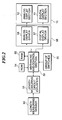
- the gauge body 3 has a length measuring sensor 50, shown in FIG. 2, built therein for converting the displacement of the spindle 2 following the displacement of the probe 1, into an electrical value. Output pulse signals from the length measuring sensor 50 are counted by a length measuring circuit (counter) 51 and output, for example, as binary coded decimal signals.
- An output from the length measuring circuit 51 is input to an arithmetic and control section 52, which in turn controls the length measuring circuit 51 and a liquid crystal drive section 56 based on operations of a group of control switches 20.
- a ROM 54 stores an arithmetic and control program for this control.
- a RAM 55 stores various data which are required to operate the arithmetic and control section 52 based on the arithmetic and control program.
- the liquid crystal drive section 56 is comprised of a digital display driver 57 and an analog display driver 58 for driving the digital display section 11 and the analog display section 12 of the liquid crystal display 10, respectively.
- the arithmetic and control section 52 compares a count value from the length measuring circuit 51 with a calibration value or a bar graph-displayed minimum value and updates a control signal provided for the analog display driver 58, that is, an offset of a bar graph-displayed value depending on a result of the comparison, as described below.
- FIG. 5 shows an operating procedure carried out to calibrate the cylinder gauge using a reference ring (not shown) and then measure a workpiece.
- the present procedure is started, and then, at a step S20, the cylinder gauge is powered on to enter a measurement mode when the ON/OFF switch 19 is depressed.
- step S30 the operator checks whether or not calibration is required. If calibration is required, the process transfers to a step S40, in which when the M/W switch 18 is depressed, the cylinder gauge enters a master adjustment mode (calibration mode).
- the preset switch 16 is used to input a value related to the reference ring (calibration value), and then the start switch 14 is depressed to prepare for measurement of the reference ring (start of a minimum value hold function) (step S55).
- step S60 the cylinder gauge is used to measure the reference ring and a minimum value is determined using the minimum value hold function.
- the preset switch 16 is depressed (step S70) to update the offset of the bar graph-displayed value in the liquid crystal display 10 such that the position of the minimum value determined at the step S60 becomes equal to the calibration value.
- the updated offset value is equal to the last or old offset + (the minimum value - the calibration value).
- step S80 After the updating of the offset to the new offset, at a step S80, when the M/W switch 18 is depressed, the calibration gauge is switched to the measurement mode.
- step S90 the operator checks whether or not setting of a tolerance, that is, the upper and lower limit values of the tolerance is required. If the setting is required, the process proceeds to a step S100.
- the tolerance setting switch 15 is depressed to prepare for inputting of an upper limit value, and at a step S110, the tolerance setting switch 15 is operated to input the upper limit value. Then, when the tolerance setting switch 15 is depressed at a step S120, inputting of a lower limit value is prepared, and at a step S130, the tolerance setting switch 15 is operated to input the lower limit value.
- step S150 the operator determines whether or not a workpiece measurement operation is to be performed. If the operation is to be performed, then at a step S160, the start switch 14 is depressed to prepare for workpiece measurement (start of the minimum value hold function).
- the cylinder gauge is used to measure the diameter of a workpiece (a minimum value is determined using the minimum value hold function), and the measured diameter value is set as the measured value. Then, at a step S180, the start switch 14 is depressed to complete the minimum value hold function.
- step S190 the operator checks at a step S190 whether or not the measurement has been completed. If the measurement has been completed, then at a step S200, the ON/OFF switch 19 is operated to terminate the operation and the cylinder gauge is powered off to terminate the process (step S210). In this case, to further continue the measurement, the process returns to the step S10.
- the preset switch 16 is operated to input the calibration value
- the tolerance setting switch 15 is manually operated to input the upper and lower limit values.
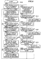
- FIG. 6 shows a digital/analog-display procedure for displaying a count value using the minimum value hold function.
- the present count value is stored in a minimum-value variable area of the RAM 55 as a minimum-value variable at a step S310 to prepare for measurement (the simple term "minimum value" in the following description refers to the value stored as this variable).
- a step S320 all the bar segments of the bar graph starting with a maximum display value (located at the right end of the bar graph) and ending with the present count value are lighted.
- a maximum display value located at the right end of the bar graph
- the method of displaying a corresponding area provides a higher visibility for a small-sized display.
- step S330 to flicker a bar segment located at a position corresponding to the minimum value as shown in FIG. 3A.
- the corresponding bar segment may be displayed in different colors.
- step S340 it is checked whether or not the present count value is smaller than the minimum value. If former is smaller than the latter, the process proceeds to a step S350. Otherwise, the process returns to the step S320.
- the present count value is stored in the minimum-value variable area of the RAM 55 and digitally displayed as a minimum value (step S360).
- a step S370 it is checked whether or not a tolerance has been set. If the tolerance has been set, a step S380 and subsequent steps are executed.
- the display of bar segments at the tolerance positions (upper and lower limit values) of the bar graph is reversed (as shown in FIG. 4A). That is, the reversal in this case means that lighted bar segments are put out, or dark bar segments are lighted, but for a display having a color bar graph, the bar segments may be displayed in different colors.
- step S390 it is checked whether or not the present count value digitally displayed as the minimum value is smaller than the set tolerance lower limit value (step S390), and if the present count value, that is, the minimum value is smaller than the tolerance lower limit value, the process proceeds to a step S400 to light a lower-limit excess mark ( ⁇ ) (FIGS. 4A, 4B, and 4C). If the result of the checking shows that the present count value is not smaller than the tolerance lower limit value, the lower-limit excess mark ( ⁇ ) is not lighted or extinguished (step S410).
- step S420 it is checked at a step S420 whether or not the present count value is larger than the set tolerance upper limit value. If the former is larger than the latter, an upper-limit excess mark (>) is lighted (step S430). If the present count value is not larger than the tolerance upper limit value, the process proceeds to a step S440 to extinguish the upper-limit excess mark (>).
- a step S450 it is determined whether or not the minimum value is within the tolerance range, that is, the lower limit value ⁇ the minimum value ⁇ the upper limit value. If the minimum value is within the tolerance range, the process proceeds to a step S460 to light an in-tolerance mark ( ⁇ ), which is shown in FIG. 1.
- the in-tolerance mark ( ⁇ ) is not lighted. If, however, the check for a tolerance setting at the S370 determines that no tolerance has been set, then at a step S480, none of the in-tolerance mark ( ⁇ ), the lower-limit excess mark ( ⁇ ), and the upper-limit excess mark (>) is lighted, as shown in FIGS. 3A, 3B, and 3C.
- step S490 it is checked whether or not the present count value is smaller than the bar graph-displayed minimum value. If the former is smaller than the latter, the process proceeds to a step S500 to change the offset of the bar graph-displayed value such that the minimum value is located at the center of the bar graph. That is, the bar graph cannot display the overall count area but can display only a range between C and C + R, where "C” denotes the offset of the bar graph-displayed value, and "R” denotes the display range of the bar graph.
- step S500 is not executed, whereby the offset of the bar graph-displayed value is not changed and only the tolerance values and their neighborhood, which will be described below, are displayed in the bar graph.
- the flowchart in FIG. 5 requires the procedure of the step S60 to be executed for calibration while requiring the procedure of the step S170 to be executed for measurement, so that the start switch 14 has to be depressed each time the minimum value hold function is resumed.
- "Automatic updating of held minimum value” avoids troubles involved in this resumption procedure.
- "Automatic updating of held minimum value” is a function of automatically updating the held minimum value, and this function automatically averages a plurality of automatically updated minimum values to determine a measured value.
- FIG. 7 is a flowchart of the operation of "Automatic uploading of held minimum value”.
- step S630 it is determined whether or not the present count value is smaller than the present value of the minimum-value variable Mi. If the former is smaller than the latter, the process proceeds to a step S640 to update the value of the minimum-value variable Mi to the present count value.
- the process proceeds to a step S650 to determine whether or not the present count value is larger than the present value of the minimum-value variable Mi by a fixed value ⁇ or more. If the former is larger than the latter, it is determined that the minimum value hold function should be resumed, that is, the minimum value held at the step S620 or S640 should be updated. Then, the process proceeds to a step S660, where the plurality of minimum values (M0, M1, M2, .7) are averaged to set the average value obtained as the measured value, and then the variable (i) incremented by one at a step S670. Subsequently, the process returns to the step S620 to again execute the operation starting at the step S620.
- a step S650 determines whether or not the present count value is larger than the present value of the minimum-value variable Mi by a fixed value ⁇ or more. If the former is larger than the latter, it is determined that the minimum value hold function should be resumed, that is, the minimum value held at the step S620 or S640 should be updated
- This procedure of FIG. 7 enables the minimum value hold function to be resumed by simply determining the minimum value a number of times and without the need of any switch operation, while enabling a plurality of minimum values to be automatically averaged to determine the measured value, thereby not only facilitating workpiece measurement or calibration but also improving measuring reliability.
- the present invention has been applied to a cylinder gauge, of course it is also applicable to other digital/analog display type measuring instruments such as a dial gauge, a micrometer, a vernier caliper, a height gauge, a depth gauge, and a test indicator.
Landscapes
- Physics & Mathematics (AREA)
- General Physics & Mathematics (AREA)
- Length Measuring Devices With Unspecified Measuring Means (AREA)
- Length-Measuring Instruments Using Mechanical Means (AREA)
- Indicating Measured Values (AREA)
Abstract
Description
Claims (17)
- An analog quantity display method of counting displacement of a probe disposed in contact with an object to be measured, and analog-displaying a count value obtained by the counting, by an analog display section as an analog quantity, comprising the steps of:displaying said count value by said analog display section as a bar graph comprising a large number of analog bars arranged in juxtaposition in one direction; andupdating an offset provided for said analog-displayed count value in a manner such that a peak value of said count value is displayed within a possible analog-display range of said analog display section, if said peak value exceeds said possible analog-display range.
- An analog quantity display method according to claim 1, wherein said offset is updated in a manner such that said peak value is displayed at a substantially central position of the possible analog-display range of said analog display section.
- An analog quantity display method according to claim 1 or 2, wherein said peak value is displayed by flickering at least one corresponding analog bar in said analog display section.
- An analog quantity display method according to claim 1 or 2, wherein said peak value is displayed by changing display color of at least one corresponding analog bar in said analog display section.
- An analog quantity display method according to claim 1, further including the step of setting a measuring tolerance and setting said offset in a manner such that a numerical value of the set tolerance is displayed within the possible analog-display range of said analog display section.
- An analog quantity display method according to claim 5, wherein the step of setting said tolerance comprises setting a plurality of tolerance values as said tolerance and setting said offset and a display scale interval of said bar graph in a manner such that said plurality of tolerance values are displayed within the possible analog-display range of said analog display section.
- An analog quantity display method according to claim 5 or 6, wherein the step of setting said tolerance comprises setting a tolerance upper limit value and a tolerance lower limit value as said tolerance and setting said offset and a display scale interval of said bar graph in a manner such that said tolerance upper limit value and tolerance lower limit value are displayed symmetrically with respect to a central position of said possible analog-display range.
- An analog quantity display method according to claim 7, wherein the step of setting said tolerance comprises setting said offset and the display scale interval of said bar graph in a manner such that said tolerance upper limit value and tolerance lower limit value are displayed symmetrically with respect to the central position of said possible analog-display range and such that a difference between said tolerance upper limit value and said tolerance lower limit value is substantially half said possible analog-display range.
- An analog quantity display method according to claim 5 or 6, wherein said numerical value of the set tolerance is displayed by reversing display state of at least one corresponding analog bar in said analog display section from a lighted state to an extinguished state or vice versa.
- An analog quantity display method according to claim 5 or 6, wherein said numerical value of the set tolerance is displayed by changing display color of at least one corresponding analog bar in said analog display section.
- An analog quantity display method according to claim 1, which is applied to a digital/analog display type measuring instrument comprising a counter for counting the displacement of the probe in contact with the measured object, a digital display section for digitally displaying the count value, and an analog display section located adjacent to the digital display section, for displaying the count value as the bar graph comprising the large number of analog bars arranged in juxtaposition in one direction.
- An analog quantity measuring method comprising the steps of:1) counting displacement of a probe disposed in contact with an object to be measured;2) comparing a count value obtained by said counting with a peak value of the count value and holding the count value as a new peak value depending upon a result of the comparison; and3) executing said step 2) again if a difference between a present value of the peak value and a present value of the count value exceeds a predetermined value.
- An analog quantity measuring method according to claim 12, further including the step of repeatedly executing said step 2) whenever a new count value is obtained at said step 1) and holding and storing a plurality of peak values.
- An analog quantity measuring method according to claim 13, further including the step of averaging all the plurality of peak values stored to determine a measured value, in executing said step 2) in said step 3).
- An analog quantity measuring method according to claim 12, which is applied to a digital/analog display type measuring instrument comprising a counter for counting the displacement of the probe in contact with the measured object, a digital display section for digitally displaying the count value, and an analog display section located adjacent to the digital display section, for displaying the count value as the bar graph comprising the large number of analog bars arranged in juxtaposition in one direction.
- A digital/analog display type measuring instrument comprising:a counter for counting displacement of a probe in contact with an object to be measured;a digital display section for digitally displaying a count value from said counter;an analog display section located adjacent to the digital display section, for displaying said count value as a bar graph comprising a large number of analog bars arranged in juxtaposition in one direction; anda control device for updating an offset provided for said analog-displayed count value in a manner such that a peak value of said count value is displayed within a possible analog-display range of said analog display section, if said peak value exceeds said possible analog-display range.
- A digital/analog display type measuring instrument according to claim 16, which is a cylinder gauge for measuring bores of cylinders.
Applications Claiming Priority (2)
| Application Number | Priority Date | Filing Date | Title |
|---|---|---|---|
| JP1000399 | 1999-01-19 | ||
| JP11010003A JP2000205852A (en) | 1999-01-19 | 1999-01-19 | Analog quantity measuring and displaying method for analog/digital display measuring instrument |
Publications (3)
| Publication Number | Publication Date |
|---|---|
| EP1022539A2 true EP1022539A2 (en) | 2000-07-26 |
| EP1022539A3 EP1022539A3 (en) | 2002-01-02 |
| EP1022539B1 EP1022539B1 (en) | 2016-11-16 |
Family
ID=11738254
Family Applications (1)
| Application Number | Title | Priority Date | Filing Date |
|---|---|---|---|
| EP00100753.3A Expired - Lifetime EP1022539B1 (en) | 1999-01-19 | 2000-01-14 | Analog quantity measuring method for a cylinder gauge |
Country Status (4)
| Country | Link |
|---|---|
| US (1) | US6412187B1 (en) |
| EP (1) | EP1022539B1 (en) |
| JP (1) | JP2000205852A (en) |
| CN (1) | CN1159567C (en) |
Cited By (6)
| Publication number | Priority date | Publication date | Assignee | Title |
|---|---|---|---|---|
| EP1503168A1 (en) * | 2003-07-29 | 2005-02-02 | Haff & Schneider GmbH & Co. OHG | Dial Gauge |
| EP1348942A3 (en) * | 2002-03-22 | 2006-07-19 | Antti Paakkinen | Method and device for defining elastic deformations and measuring the internal angle of a gyratory compactor |
| EP1762816A1 (en) * | 2005-09-12 | 2007-03-14 | Mitutoyo Corporation | Digital measuring instrument |
| EP2056062A1 (en) * | 2007-11-05 | 2009-05-06 | Mitutoyo Corporation | Measuring instrument |
| ITMI20091072A1 (en) * | 2009-06-17 | 2010-12-18 | Giusta Misura S A S Di Aldo Pon Terio & C | MANUAL MEASUREMENT OF A DIGITAL READING LENGTH |
| CN102735198A (en) * | 2012-07-12 | 2012-10-17 | 苏州康斯坦普工程塑料有限公司 | Machine cylinder measuring instrument |
Families Citing this family (31)
| Publication number | Priority date | Publication date | Assignee | Title |
|---|---|---|---|---|
| JP2002054942A (en) * | 2000-08-09 | 2002-02-20 | Honda Motor Co Ltd | Remaining distance meter |
| USD478019S1 (en) | 2001-09-24 | 2003-08-05 | Melius Sa | Indicator |
| US6901675B2 (en) * | 2003-05-27 | 2005-06-07 | Bristol Compressors, Inc. | System and method for sizing a center bore of a laminated rotor |
| USD521883S1 (en) * | 2004-06-01 | 2006-05-30 | Melius Sa | Indicator |
| FR2898671B1 (en) * | 2006-03-14 | 2008-12-26 | Snecma Sa | SYSTEM FOR MEASURING RATINGS WITHIN A HOLLOW SHAFT, IN PARTICULAR AERONAUTICAL TURBOMACHINE |
| DE102006013695A1 (en) * | 2006-03-24 | 2007-09-27 | Robert Bosch Gmbh | Electro-optical display unit for hand-held length measuring device e.g. roller-tape, has digital display comprising variable scale with scale point and numerical value, where orientation of scale is changed relative to display unit |
| US7441460B2 (en) * | 2006-11-07 | 2008-10-28 | Precision Medical, Inc. | Vacuum regulator with two gauges |
| JP5192144B2 (en) * | 2006-12-12 | 2013-05-08 | 株式会社ミツトヨ | Measuring instrument |
| US20080210336A1 (en) * | 2007-03-01 | 2008-09-04 | Shiraz Balolia | Systems and methods for measuring height of jointer infeed surface |
| US7913411B2 (en) * | 2008-03-21 | 2011-03-29 | Dorsey Metrology International | Digital bore gage handle |
| US7546694B1 (en) * | 2008-04-03 | 2009-06-16 | Il Poom Jeong | Combination drawing/measuring pen |
| JP5687820B2 (en) * | 2008-10-21 | 2015-03-25 | 株式会社ミツトヨ | Measuring instrument |
| DE102009010810B4 (en) * | 2009-02-27 | 2018-03-22 | Continental Automotive Gmbh | Device for displaying several detectable variables |
| DE102009011015B4 (en) * | 2009-02-28 | 2017-06-22 | Bayerische Motoren Werke Aktiengesellschaft | Method for displaying a remaining range of a motor vehicle |
| US20110000344A1 (en) * | 2009-07-01 | 2011-01-06 | Jeremy Summers | Depth gauge and adjustment tool for adjustable fastener receptacles and method |
| USD670585S1 (en) * | 2011-04-15 | 2012-11-13 | Mitutoyo Corporation | Inside diameter measurement tool |
| JP5970295B2 (en) * | 2011-09-05 | 2016-08-17 | 株式会社ミツトヨ | Measuring instrument |
| JP5918978B2 (en) * | 2011-11-10 | 2016-05-18 | 株式会社ミツトヨ | Measuring instrument |
| JP2013200248A (en) * | 2012-03-26 | 2013-10-03 | Mitsutoyo Corp | Digital indicator and multipoint measurement device |
| US9132213B2 (en) * | 2012-08-20 | 2015-09-15 | Precision Medical, Inc. | Vacuum regulator with pre-set and calibration features |
| JP6109536B2 (en) * | 2012-11-13 | 2017-04-05 | 株式会社ミツトヨ | indicator |
| TWM472833U (en) * | 2013-08-13 | 2014-02-21 | Taiwan Power Testing Technology Co Ltd | Electronic type welded joint detecting gauge |
| JP6608579B2 (en) | 2014-04-03 | 2019-11-20 | 株式会社ミツトヨ | Measuring instrument |
| KR101693924B1 (en) * | 2014-07-30 | 2017-01-09 | 현대자동차주식회사 | Small sealing gauge |
| JP6537841B2 (en) * | 2015-02-16 | 2019-07-03 | 株式会社ミツトヨ | Inner measuring instrument |
| US9669941B1 (en) * | 2016-01-31 | 2017-06-06 | Rockwell Collins, Inc. | Weather indicator system and method |
| JP6847516B2 (en) * | 2017-01-26 | 2021-03-24 | 株式会社ミツトヨ | Measuring instrument |
| US10859363B2 (en) | 2017-09-27 | 2020-12-08 | Stanley Black & Decker, Inc. | Tape rule assembly with linear optical encoder for sensing human-readable graduations of length |
| JP7208717B2 (en) * | 2018-04-20 | 2023-01-19 | 株式会社ミツトヨ | Small measuring instrument and its control method |
| US12548180B2 (en) | 2023-04-13 | 2026-02-10 | Mitutoyo Corporation | Hole diameter measuring device |
| DE102025101144B3 (en) | 2025-01-14 | 2026-05-13 | Ifm Electronic Gmbh | Display device for showing process values |
Family Cites Families (27)
| Publication number | Priority date | Publication date | Assignee | Title |
|---|---|---|---|---|
| DE2832999A1 (en) | 1977-07-29 | 1979-02-15 | Sharp Kk | ELECTROCHROME DISPLAY DEVICE |
| JPS5812591B2 (en) * | 1977-11-01 | 1983-03-09 | 横河電機株式会社 | display device |
| US4289382A (en) | 1978-04-04 | 1981-09-15 | Federal Products Corporation | Measurement system for machine parts |
| CH630174A5 (en) * | 1978-04-05 | 1982-05-28 | Hans Meyer | INTERIOR MEASURING DEVICE. |
| CH627906B (en) | 1978-11-21 | Berney Sa Jean Claude | ANALOGUE DISPLAY DEVICE. | |
| JPS55152412A (en) * | 1979-05-16 | 1980-11-27 | Toyoda Mach Works Ltd | Dimension measuring device for work |
| JPS5819503A (en) * | 1981-07-28 | 1983-02-04 | Mitsutoyo Mfg Co Ltd | Size measuring device |
| JPS5975111A (en) | 1982-10-22 | 1984-04-27 | Ichiro Katayama | Display device of dial gauge |
| JPS59193306A (en) | 1983-04-19 | 1984-11-01 | Mitsutoyo Mfg Co Ltd | Dimension measuring apparatus |
| DE3408026A1 (en) * | 1984-03-05 | 1985-09-12 | Brown, Boveri & Cie Ag, 6800 Mannheim | DIGITAL MEASURING DEVICE FOR QUASI ANALOG MEASUREMENT DISPLAY |
| US4604809A (en) * | 1985-04-05 | 1986-08-12 | Meyer Jr Franklin | Gage head actuating coupler |
| US4905378A (en) * | 1985-08-26 | 1990-03-06 | Lockheed Corporation | Centralizing countersink gauge |
| DE3611681A1 (en) | 1986-04-08 | 1987-10-15 | Bbc Brown Boveri & Cie | DIGITAL MEASUREMENT METHOD FOR QUASIANALOGUE MEASUREMENT DISPLAY |
| JPS62285012A (en) | 1986-06-03 | 1987-12-10 | Mitsutoyo Corp | Measuring device with electric power generating function |
| DE3622632C2 (en) | 1986-07-05 | 1995-11-30 | Fichtel & Sachs Ag | Electronic device for measuring and displaying the speed and other data on a bicycle |
| US4839833A (en) * | 1987-01-21 | 1989-06-13 | Mustafa Parhiskari | Programmable display engineering scale |
| JPH0455713A (en) | 1990-06-26 | 1992-02-24 | Kajirou Watanabe | Method and apparatus for detecting amount of displacement |
| JP2572149B2 (en) * | 1990-07-02 | 1997-01-16 | 株式会社東京精密 | Dimension display device |
| US5251381A (en) * | 1991-10-17 | 1993-10-12 | Northrop Corporation | Precision angularity hole checker with indicator |
| US5317814A (en) * | 1992-04-10 | 1994-06-07 | Central Tools, Inc. | Measuring caliper instrument having a digital display and method for calibrating same |
| WO1993023725A1 (en) | 1992-05-14 | 1993-11-25 | Denove Thomas F | Lcd bargraph motion picture light meter |
| US5313713A (en) * | 1992-08-14 | 1994-05-24 | Zircon Corporation | Electronic level with display scale and audible tone scale |
| JPH06201407A (en) * | 1992-09-16 | 1994-07-19 | Caterpillar Inc | Method and apparatus for displaying sensor output in diagnostic system |
| US5440819A (en) * | 1994-04-19 | 1995-08-15 | Comtorgage Corporation | Actuator and programmable amplifier for an expanding plug gage head |
| JP3222053B2 (en) * | 1996-01-16 | 2001-10-22 | 株式会社東京精密 | External dimensions measuring device |
| JP3372793B2 (en) | 1996-11-05 | 2003-02-04 | 株式会社ミツトヨ | Digital / analog display type measuring instrument |
| JP3710930B2 (en) | 1998-03-02 | 2005-10-26 | 矢崎総業株式会社 | Multiple display instrument |
-
1999
- 1999-01-19 JP JP11010003A patent/JP2000205852A/en active Pending
-
2000
- 2000-01-11 US US09/480,998 patent/US6412187B1/en not_active Expired - Lifetime
- 2000-01-14 EP EP00100753.3A patent/EP1022539B1/en not_active Expired - Lifetime
- 2000-01-19 CN CNB001016229A patent/CN1159567C/en not_active Expired - Lifetime
Cited By (10)
| Publication number | Priority date | Publication date | Assignee | Title |
|---|---|---|---|---|
| EP1348942A3 (en) * | 2002-03-22 | 2006-07-19 | Antti Paakkinen | Method and device for defining elastic deformations and measuring the internal angle of a gyratory compactor |
| AU2003202409B2 (en) * | 2002-03-22 | 2009-06-04 | Antti Paakkinen | Method and device for defining elastic deformations and integral angle of a gyratory compactor |
| EP1503168A1 (en) * | 2003-07-29 | 2005-02-02 | Haff & Schneider GmbH & Co. OHG | Dial Gauge |
| CN100513989C (en) * | 2003-07-29 | 2009-07-15 | 哈夫·施奈德有限公司及两合公司 | Dial gauge |
| EP1762816A1 (en) * | 2005-09-12 | 2007-03-14 | Mitutoyo Corporation | Digital measuring instrument |
| US7395610B2 (en) | 2005-09-12 | 2008-07-08 | Mitutoyo Corporation | Digital measuring instrument |
| EP2056062A1 (en) * | 2007-11-05 | 2009-05-06 | Mitutoyo Corporation | Measuring instrument |
| US7721455B2 (en) | 2007-11-05 | 2010-05-25 | Mitutoyo Corporation | Measuring instrument |
| ITMI20091072A1 (en) * | 2009-06-17 | 2010-12-18 | Giusta Misura S A S Di Aldo Pon Terio & C | MANUAL MEASUREMENT OF A DIGITAL READING LENGTH |
| CN102735198A (en) * | 2012-07-12 | 2012-10-17 | 苏州康斯坦普工程塑料有限公司 | Machine cylinder measuring instrument |
Also Published As
| Publication number | Publication date |
|---|---|
| US6412187B1 (en) | 2002-07-02 |
| EP1022539B1 (en) | 2016-11-16 |
| JP2000205852A (en) | 2000-07-28 |
| CN1261660A (en) | 2000-08-02 |
| EP1022539A3 (en) | 2002-01-02 |
| CN1159567C (en) | 2004-07-28 |
Similar Documents
| Publication | Publication Date | Title |
|---|---|---|
| EP1022539B1 (en) | Analog quantity measuring method for a cylinder gauge | |
| US7721455B2 (en) | Measuring instrument | |
| JPH0535809B2 (en) | ||
| JPH07280504A (en) | Layer-thickness measuring device | |
| JP3683350B2 (en) | Electronic level gauge and electronic level | |
| JP7801075B2 (en) | Test Indicator | |
| JPH01162115A (en) | Electronic scales | |
| JPH10142001A (en) | Measuring device | |
| US12148286B2 (en) | Precision length measuring device | |
| JP3372793B2 (en) | Digital / analog display type measuring instrument | |
| EP0657717A1 (en) | Wrist watch with compass and anemometer | |
| CN117321383A (en) | digital level | |
| KR100336437B1 (en) | The electronic angle measuring instrument | |
| US7546218B2 (en) | Dimension measuring device | |
| US6069474A (en) | Load sensing device with load detection signal correction apparatus and method | |
| JP2724678B2 (en) | Planar accuracy measuring device, its input device and monitoring device | |
| JP2000162104A (en) | Material testing machine | |
| JP2783283B2 (en) | Image characteristic evaluation device | |
| JPH0631394Y2 (en) | Clear rain gauge | |
| GB2116724A (en) | Microscope for measuring and displaying dimensions electrically | |
| JPH0829129A (en) | Length measuring device | |
| JP2891467B2 (en) | Level measuring device | |
| JP2880735B2 (en) | Level display device | |
| JPH0227611B2 (en) | ||
| JP2001012939A (en) | Measuring device |
Legal Events
| Date | Code | Title | Description |
|---|---|---|---|
| PUAI | Public reference made under article 153(3) epc to a published international application that has entered the european phase |
Free format text: ORIGINAL CODE: 0009012 |
|
| AK | Designated contracting states |
Kind code of ref document: A2 Designated state(s): DE FR GB Kind code of ref document: A2 Designated state(s): AT BE CH CY DE DK ES FI FR GB GR IE IT LI LU MC NL PT SE |
|
| AX | Request for extension of the european patent |
Free format text: AL;LT;LV;MK;RO;SI |
|
| PUAL | Search report despatched |
Free format text: ORIGINAL CODE: 0009013 |
|
| AK | Designated contracting states |
Kind code of ref document: A3 Designated state(s): AT BE CH CY DE DK ES FI FR GB GR IE IT LI LU MC NL PT SE |
|
| AX | Request for extension of the european patent |
Free format text: AL;LT;LV;MK;RO;SI |
|
| RIC1 | Information provided on ipc code assigned before grant |
Free format text: 7G 01B 7/00 A, 7G 01D 7/00 B, 7G 01R 13/40 B |
|
| 17P | Request for examination filed |
Effective date: 20020515 |
|
| AKX | Designation fees paid |
Free format text: DE FR GB |
|
| 17Q | First examination report despatched |
Effective date: 20071128 |
|
| GRAP | Despatch of communication of intention to grant a patent |
Free format text: ORIGINAL CODE: EPIDOSNIGR1 |
|
| INTG | Intention to grant announced |
Effective date: 20160630 |
|
| RIN1 | Information on inventor provided before grant (corrected) |
Inventor name: TSUYUKI, NORIHIDE Inventor name: KUJI, YOSHITAKA Inventor name: OHTA, HIROYUKI Inventor name: SUZUKI, MIKIO Inventor name: SASAKI, KOJI Inventor name: ICHIKAWA, YUICHI |
|
| GRAS | Grant fee paid |
Free format text: ORIGINAL CODE: EPIDOSNIGR3 |
|
| GRAA | (expected) grant |
Free format text: ORIGINAL CODE: 0009210 |
|
| AK | Designated contracting states |
Kind code of ref document: B1 Designated state(s): DE FR GB |
|
| REG | Reference to a national code |
Ref country code: GB Ref legal event code: FG4D |
|
| REG | Reference to a national code |
Ref country code: DE Ref legal event code: R096 Ref document number: 60049497 Country of ref document: DE |
|
| REG | Reference to a national code |
Ref country code: FR Ref legal event code: PLFP Year of fee payment: 18 |
|
| REG | Reference to a national code |
Ref country code: DE Ref legal event code: R097 Ref document number: 60049497 Country of ref document: DE |
|
| PLBE | No opposition filed within time limit |
Free format text: ORIGINAL CODE: 0009261 |
|
| STAA | Information on the status of an ep patent application or granted ep patent |
Free format text: STATUS: NO OPPOSITION FILED WITHIN TIME LIMIT |
|
| 26N | No opposition filed |
Effective date: 20170817 |
|
| REG | Reference to a national code |
Ref country code: FR Ref legal event code: PLFP Year of fee payment: 19 |
|
| PGFP | Annual fee paid to national office [announced via postgrant information from national office to epo] |
Ref country code: FR Payment date: 20190123 Year of fee payment: 20 Ref country code: GB Payment date: 20190121 Year of fee payment: 20 Ref country code: DE Payment date: 20190123 Year of fee payment: 20 |
|
| REG | Reference to a national code |
Ref country code: DE Ref legal event code: R071 Ref document number: 60049497 Country of ref document: DE |
|
| REG | Reference to a national code |
Ref country code: GB Ref legal event code: PE20 Expiry date: 20200113 |
|
| PG25 | Lapsed in a contracting state [announced via postgrant information from national office to epo] |
Ref country code: GB Free format text: LAPSE BECAUSE OF EXPIRATION OF PROTECTION Effective date: 20200113 |