EP1022464A2 - Compressor valve - Google Patents
Compressor valve Download PDFInfo
- Publication number
- EP1022464A2 EP1022464A2 EP00300057A EP00300057A EP1022464A2 EP 1022464 A2 EP1022464 A2 EP 1022464A2 EP 00300057 A EP00300057 A EP 00300057A EP 00300057 A EP00300057 A EP 00300057A EP 1022464 A2 EP1022464 A2 EP 1022464A2
- Authority
- EP
- European Patent Office
- Prior art keywords
- cylinder
- recess
- suction
- fluid
- reed valve
- Prior art date
- Legal status (The legal status is an assumption and is not a legal conclusion. Google has not performed a legal analysis and makes no representation as to the accuracy of the status listed.)
- Withdrawn
Links
- 235000014676 Phragmites communis Nutrition 0.000 claims abstract description 78
- 239000012530 fluid Substances 0.000 claims abstract description 47
- 238000013459 approach Methods 0.000 description 2
- 230000006835 compression Effects 0.000 description 1
- 238000007906 compression Methods 0.000 description 1
- 238000007599 discharging Methods 0.000 description 1
- 238000006073 displacement reaction Methods 0.000 description 1
- 230000002093 peripheral effect Effects 0.000 description 1
- 238000007789 sealing Methods 0.000 description 1
- 238000000926 separation method Methods 0.000 description 1
- 238000000638 solvent extraction Methods 0.000 description 1
Images





Classifications
-
- F—MECHANICAL ENGINEERING; LIGHTING; HEATING; WEAPONS; BLASTING
- F04—POSITIVE - DISPLACEMENT MACHINES FOR LIQUIDS; PUMPS FOR LIQUIDS OR ELASTIC FLUIDS
- F04B—POSITIVE-DISPLACEMENT MACHINES FOR LIQUIDS; PUMPS
- F04B39/00—Component parts, details, or accessories, of pumps or pumping systems specially adapted for elastic fluids, not otherwise provided for in, or of interest apart from, groups F04B25/00 - F04B37/00
- F04B39/10—Adaptations or arrangements of distribution members
- F04B39/1073—Adaptations or arrangements of distribution members the members being reed valves
Definitions
- This invention relates to a fluid suction/discharge apparatus, such as a fluid compressor, and, in particular, to improvements of a valve mechanism of such an apparatus.
- a fluid suction/discharge apparatus generally includes a cylinder block defining a cylinder bore of a cylinder, which has a closed end. The closed end is formed by a valve plate that is secured to the cylinder block.
- the valve plate has an inlet port for fluid suction, and an outlet port for fluid discharge.
- a piston is slidably close-fitted into the cylinder, and therefore, can slide in the axial direction of the cylinder As the piston approaches, or moves towards, the closed end of the cylinder, the fluid is discharged from inside of the cylinder through the outlet port. On the other hand, as the piston leaves, or moves away from, the closed end, the fluid is sucked, or introduced, into the inside of the cylinder through the inlet port.
- the apparatus further has a suction reed valve disposed on the inner surface of the closed end, and a discharge reed valve disposed on the outer surface of the closed end.
- the suction reed valve extends along the inner surface over the inlet port, with one end of the suction reed valve fixed to the cylinder, and the other end of the suction reed valve being flexible in the axial direction.
- the cylinder is integrally formed with a recess in the inner surface thereof.
- the recess extends from the closed end of the cylinder in the axial direction.
- the recess has a bottom to receive the flexible end of the suction reed valve in a suction condition.
- the existing apparatus has at least one shortcoming.
- the suction reed valve bends, and thereby, the inlet port opens.
- a gap is formed between the suction reed valve and the valve plate.
- the gap partially opens into the recess, so that the gap and the inlet port form a passage for fluid to flow therethrough into the cylinder.
- the introduced fluid passes through the passage, and then, interacts with the bottom of the recess and "bounces" back therefrom.
- the "bounced" fluid forms an eddy between the bottom and the suction reed valve.
- This eddy prevents the suction reed valve from touching the bottom, so that the passage for fluid narrows.
- the eddy causes the suction reed valve to vibrate. Such vibration results in a jarring noise, which can be annoying to a passenger in a vehicle in which the fluid compressor is used.
- This invention therefore provides a fluid suction/discharge apparatus which can prevent the vibration of the suction reed valve in the suction condition.
- a recess which is formed with a cylinder and extends from a closed end of the cylinder in the axial direction of the cylinder, comprises deep and shallow recesses that are integral with each other.
- the shallow recess has a bottom to receive a flexible end of a suction reed valve in a suction condition.
- the deep recess forms a passage for fluid, while the flexible end of the suction reed valve is received on the bottom of the shallow recess.
- the passage becomes wide in comparison with an existing apparatus, so that the vibration is reduced or eliminated.
- the fluid suction/discharge apparatus may be a compressor.
- Reciprocal motion type compressor (herein referred to as a compressor) 101, according to one embodiment of the present invention, is provided in Fig. 1 .
- Compressor 101 comprises compressor casing 102 into which front housing 103, cylinder block 104, cylinder head 105, valve plate 106, and so forth, are assembled.
- front housing 103 is arranged on one side of the cylinder block 104, while cylinder head 105 is arranged on the opposite side of cylinder block 104.
- Valve plate 106 is interposed between cylinder block 104 and cylinder head 105.
- Cylinder gasket 107 and a head gasket may be fitted in compressor casing 102 as sealing members. Cylinder gasket 107 serves to seal a gap between cylinder block 104 and valve plate 106, while head gasket (not shown) serves to seal a gap between cylinder head 105 and valve plate 106. For the sake of clarity, head gasket is not shown in Fig. 1 .
- Cylinder block 104 and front housing 103 have through-holes 111 and 112.
- Driving shaft 108 is inserted into through-holes 111 and 112, and is rotatably supported by front housing 103 and cylinder block 104 via bearings 113 and 114, supporting member 115, etc.
- Front housing 103 defines crank chamber 117 in cooperation with cylinder block 104.
- rotor 118 is mounted on driving shaft 108 via stopper pin 119.
- Swash plate 121 is coupled to rotor 118 via a hinge mechanism.
- Rotor 118 and swash plate 121 may have tabs 124 and 125, respectively.
- Tab 124 may be fitted with guide pin 124a, while tab 125 may be formed with track-shaped guide hole 125a.
- Guide pin may be movably engaged with guide hole 125a, and thereby, tabs 124 and 125 and guide pin 124a may comprise the above-mentioned hinge mechanism.
- Driving shaft 108 passes through swash plate 121 so that swash plate 121 abuts driving shaft 108 at an inner periphery thereof, so as to rotate together with driving shaft 108.
- An inclination of swash plate 121 relative to driving shaft 108 can be changed by means of the hinge mechanism.
- Wobble plate 122 is slidably mounted on swash plate 121 via bearings 126 and 127.
- Wobble plate 122 is fitted with guide plate 128 fixedly arranged in cylinder block 104, so as to wobble in a longitudinal direction of guide plate 128. With this structure, wobble plate 122 does not rotate, but wobbles in a direction parallel to driving shaft 108, while swash plate 121 rotates.
- Cylinder block 104 defines a plurality of cylinders 116, in cooperation with valve plate 106, which serves as the closed ends of cylinders 116.
- Cylinders 116 are equiangularly arranged about a shaft axis of driving shaft 108. Cylinders 116 extend in parallel to driving shaft 108. The direction in which cylinder 116 extends will be referred as to the "axial direction.”
- a plurality of piston rods 123 are coupled to wobble plate 122 through a ball connection. Furthermore, each of piston rods 123 is coupled through the ball connection to a corresponding one of pistons 110 which is slidably close-fitted into respective cylinders 116.
- Cylinder head 105 comprises outer wall 141a formed in a bowl-shape or a tray-shape, and inner wall 141b partitioning the interior of cylinder head 105. Inner and outer walls 141a and 141b form discharge chamber 143 and suction chamber 142 in cylinder head 105, cooperating with valve plate 106. Cylinder head 105 further comprises a suction port for supplying the fluid to suction chamber 142, and a discharge port for discharging fluid from discharge chamber 143 to the outside of the compressor, both of which, for simplicity, are not shown in Fig. 1 .
- valve plate 106 is secured to cylinder block 104, so as to form closed ends of cylinders 116.
- Valve plate 106 has inlet ports 131 for fluid suction and outlet ports 132 for fluid discharge. Inlet and outlet ports 131 and 132 correspond to respective cylinders 116.
- the fluid is discharged from inside of corresponding cylinder 116 to discharge chamber 143 through corresponding outlet port 132. Further, as one piston 110 moves away from the corresponding closed end, the fluid is sucked, or introduced, from suction chamber 142 into the inside of corresponding cylinder 116 through its corresponding inlet port 131.
- Suction reed valve member 129 is fitted on a principal surface of valve plate 106 at a side of cylinder block 104, while discharge reed valve member 133 is fitted on the other principal surface of valve plate 106.
- the principal surface is also referred to as an inner surface of valve plate 106, while the other surface is referred to as an outer surface of valve plate 106.
- Suction reed valve member 129 has a plurality of suction reed valves 129b which extend along the inner surface of valve plate 106 over respective inlet ports 131.
- Discharge reed valve member 133 has a plurality of discharge reed valves 133b which extend along the outer surface of valve plate 106 over respective outlet ports 133b.
- Suction reed valves 129b have flexible outer ends, so that each flexible end can bend in a suction condition of cylinder 116, and thereby inlet port 131 can open.
- valve plate 106 has seven inlet holes 131 and seven outlet holes 132.
- Suction reed valve member 129 and discharge reed valve member 133 radially branch from the center thereof in seven directions.
- Discharge reed valve stopper 135 is used to receive discharge reed valve 133b in discharge condition. Stopper 135 is formed as a plate which also radially branches from the center thereof in seven direction.
- screw holes 129a and 133a are formed, respectively.
- other screw holes 106a and 135a are formed at the centers of valve plate 106 and discharge reed valve stopper 135, respectively.
- Suction reed valve member 129, valve plate 106, discharge reed valve member 133, and discharge reed valve stopper 135 are assembled in this order, with screw holes 129a, 106a, 133a, 135a all fixed by screw 145, washer 146, and nut 147.
- suction reed valves 129b close respective inlet ports 131, while discharge reed valves 133b close respective outlet ports 132.
- suction reed valve member 129 has seven holes 148, which may be of an oval shape, to communicate cylinders 116 with outlet ports 132.
- Recesses 134 are formed within cylinders 116 at one side of cylinder gasket 107, as illustrated in Fig. 2 . Recesses 134 extend from surface 151 of cylinder block 104, and may be located on extension lines connecting between the center of through hole 112 and the centers of respective cylinders 116.
- Cylinder gasket 107 has center hole 152 arranged at a center thereof, cylinder holes 153 surrounding center hole 152, and screw holes 154.
- Center hole 152 is the same size as the cross section of through hole 112
- cylinder holes 153 are the same size as the cross section of cylinders 116 with recesses 134.
- Head gasket 130 has a large center hole 155, in comparison with cylinder gasket 107, and suction holes 156 which surround large center hole 155 and correspond to inlet holes 131. That is, the number of the illustrated suction holes 156 is seven.
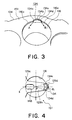
- cylinder 116 is formed with recess 134 which extends from surface 151 to flat bottom 134a located at predetermined depth, as shown in Fig. 3 .
- Flat bottom 134a is perpendicular to side-wall 134b of recess 134.
- Side-wall 134b is integrally formed with beveled or chamfered portions 116a of cylinder 116, though edges 134c and 134d are formed on boundaries between side-wall 134b and beveled portions 116a.
- the existing valve mechanism with the above structure should have a movement as indicated in Fig. 5 . That is, in the suction condition, piston 110 moves away from valve plate 106, so that flexible end 129d bends toward piston 110. As the results, inlet port 131 opens, while flexible end 129d is received on flat bottom 134a of recess 134.
- the existing valve mechanism may not have such a movement.
- flexible end 129d of suction reed valve 129b bends, and thereby, inlet port 131 starts to open.
- a gap is formed between suction reed valve 129b and valve plate 106.
- the gap partially opens into recess 134.
- the gap and inlet port 131 form a narrow passage for fluid to flow therethrough into cylinder 116. Because the passage is narrow, the introduced fluid passes through the passage to be accelerated, and then interacts with bottom 134a of recess 134 to "bounce" back therefrom.
- the fluid forms an eddy between bottom 134a and flexible end 129d, which prevents flexible end 129d of suction reed valve 129b from touching bottom 134a, so that the passage for fluid becomes narrow.
- the eddy "excites" suction reed valve 129b, and causes it to vibrate. Such vibration results in making a jarring noise, which may be annoying to a passenger in a vehicle.
- recess 10 and beveled, or chamfered, portion 116a are integrally formed with recess 10 at surface 151.
- recess 10 comprises shallow recess 12 and a pair of deep recesses 13 and 14 arranged at both sides of shallow recess 12.
- Shallow and deep recesses 12, 13, and 14 are integral with each other.
- Beveled portion 116a is formed, by beveling, at a part of an edge of the cylinder.
- Beveled portion 116a has a particular shape which is wider as it approaches the recess, and is smoothly integral with deep recesses 13 and 14. Thus, there is no edge on the boundary between deep recesses 13 and 14 and beveled portion 116a.
- Shallow recess 12 has flat bottom 12a to receive flexible end 25 of suction reed valve 22 (shown in Fig. 10 ), in a suction condition.
- Deep recesses 13 and 14 are adapted to form passages for fluid at both sides of shallow recess 12 receiving flexible end 25 of suction reed valve 22 in the suction condition.
- a profile of recess 10 is larger than that of existing recess 134. That is, a curve line presented by recess 10 is longer than the other curve line presented by existing recess 134, in the plan views. In addition, the curve line of recess 10 is gentler than the curve line of recess 134.
- ⁇ 2 denotes an angle between both side edges of entire recess 10
- ⁇ 3 denotes another angle between both side edges of shallow recess 12, in Fig. 9A .
- Recess 10 and existing recess 134 have the following relationship of angles: ⁇ 2 > ⁇ 1 > ⁇ 3 .
- the angles ⁇ 2 and ⁇ 3 should be determined to meet the requirement of the compressor to be applied with recess 10.
- Recess 10 has a shape symmetrical to the extension line 1 between the center of through hole 112 and the center P, as viewed from the valve plate side.
- Flat bottom 12a is perpendicular to side wall 11 of shallow recess 12 and is parallel to surface 151 of cylinder block 104.
- deep recesses 13 and 14 both present smooth curves with no edges. In other words, deep recesses 13 and 14 both have curved planes which smoothly change in a radius direction of cylinder 116 as a depth of the deep recess becomes deeper. An angular separation between beveled portion 116a and side wall 11 of shallow recess 12 is absorbed by the smooth curve presented by deep recesses 13 and 14.
- deep recesses 13 and 14 become narrower as the depth of the deep recesses are deeper.
- dotted lines shown in Fig. 7 merely indicate boundaries between upper and under sides of the level where flat bottom 12a exists.
- the level is L 1 in depth, as shown in Fig. 9B , and is determined to be equal to the level of flat bottom 134a of existing recess 134, in this embodiment.
- the depth of the deepest part of deep recesses 13 and 14 is L 2 , wherein L 2 is greater than L 1 .
- the desirable range of the depth L 2 may allow a condition that upper end of piston 110 does not reach the deepest points of deep recesses 13 and 14 if piston 110 arrives at a point closest to valve plate 106.
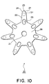
- suction reed valve member 20 has center portion 26 which is formed in a circular shape having a predetermined radius, and radially branches from center portion 26 in seven directions.
- the branches form suction reed valves 22 corresponding to inlet ports 131, respectively.
- suction reed valve member 20 has oval holes 23 that are formed at starting points of the respective branches, to communicate cylinders 116 with outlet ports 132.
- Such holes 23 may be track-shaped or may be in an elongated form.
- suction reed valve member 20 is fixed with valve plate 106, and so forth, by screw 145, washer 146, and nut 147, as shown in Fig. 2 .
- suction reed valve member 20 is entirely formed with elastic member in this embodiment.
- Each of suction reed valves 22 has a shape that is symmetrical to the extension line 1 between the center of through hole 112 and the center P, as viewed from the valve plate side.
- suction reed valve 22 tapers with an angle (called a first angle), and further tapers to flexible end 25 of suction reed valve 22 with another angle (called a second angle) that is larger than the first angle.
- the further tapered portion is called tapered portion 24, and is formed with flexible end 25.
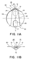
- Flexible end 25 has a tip profile substantially equal to a part of flat bottom 12a of shallow recess 12, as shown in Fig. 11A . Because suction reed valve 22 has tapered portion 24, when flexible end 25 is received on flat bottom 12a, deep recesses 13 and 14 are not closed by flexible end 25 but form wide passage for fluid suction, as illustrated in Fig. 11B .
- the other end of suction reed valve 22, namely center portion 26 in this embodiment, is fixedly interposed between valve plate 106 and cylinder block 104, in particular, cylinder gasket 107. And also, oval hole 23 shares a part of its peripheral profile with cylinder 116, as shown in Fig. 11A .
- the introduced fluid through inlet port 131 does not result in an eddy between bottom 12a and flexible end 25, but smoothly passes into cylinder 116, as shown in Figs. 11B and 12. Further, if the amount of fluid passing through inlet port 131 is large, flat bottom 12a of shallow recess 12 receives flexible end 25 thereon. Even if the amount of the fluid is small, the wide passages formed by deep recesses 13 and 14 cause the fluid velocity to slow down and prevent the occurrence of the eddy.
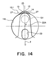
- the tapered portion of suction reed valve 22A has a pair of cut-away portions 27 which correspond to deep recesses 13 and 14, respectively.
- Each of cut-away portions 27 has a particular shape, such as an arc, so that flexible end 25 is further tapered in comparison with the foregoing suction reed valve 22 illustrated in Figs. 10 and 11 .
- edge of cut-away portion 27 forms in common to an edge of flexible end 25, and locates on a boundary between shallow and deep recesses 12, 13 and 14 other than a radial inner part thereof.
- the radial inner part of the edge of cut-away portion 27 is arranged to be within cylinder 116.
- suction reed valve 22A with cut-away portions allows deep recesses 13 and 14 to form wider passages.
- the fluid passing through inlet port 131 is much smoothly introduced into cylinder 116.
- the particular shape of cut-away potion may be any shape if flexible end 25 does not stick out from flat bottom 12a of shallow recess 12 when flexible end 25 is received on flat bottom 12a.
- the number of cylinders may six, eight, any number, though the number of cylinders is seven in the above explanations.
- the compressor may be of the fixed displacement type.
Landscapes
- Engineering & Computer Science (AREA)
- Mechanical Engineering (AREA)
- General Engineering & Computer Science (AREA)
- Compressor (AREA)
- Check Valves (AREA)
Abstract
Description
Claims (7)
- A fluid suction/discharge apparatus comprising:a cylinder block defining a cylinder and a recess, said recess being integrally formed with the cylinder and extending from one end of the cylinder in an axial direction of the cylinder;a valve plate secured to the cylinder block to form a closed end of the cylinder and having an inlet port and an outlet port;a piston slidably received in the cylinder, the piston being slidable in the axial direction; anda flexible suction reed valve having a first and a second end, the first end being secured to the cylinder and extending along an inner surface of the valve plate over the inlet port, the second end of said suction reed valve being received in the recess;
wherein:the recess comprises a deep recess and a shallow recess that are integral with each other; andthe shallow recess having a bottom adapted to receive the flexible end of the suction reed valve in a suction condition, and the deep recess forming a passage for fluid. - The fluid suction/discharge apparatus of claim 1, wherein the deep recess comprises a pair of deep recess portions formed at both sides of the shallow recess.
- The fluid suction/discharge apparatus of claim 1, wherein:the deep recess has a curved plane which smoothly changes in a radial direction of the cylinder as a depth of the deep recess increases.
- The fluid suction/discharge apparatus of claim 1, wherein the cylinder block has a beveled portion formed at a part of an edge of the cylinder and integral with the recess.
- The fluid suction/discharge apparatus of claim 4, wherein the bevel portion has a width that gradually increases near the recesses.
- The fluid suction/discharge apparatus of claim 1, wherein the suction reed valve has a cut-away portion at the second end thereof, wherein the cut-away portion increases a size of the fluid passage.
- The fluid suction/discharge apparatus of claim 1, wherein the fluid suction/discharge apparatus is a compressor.
Applications Claiming Priority (2)
| Application Number | Priority Date | Filing Date | Title |
|---|---|---|---|
| JP11010483A JP2000205135A (en) | 1999-01-19 | 1999-01-19 | Reciprocating compressor |
| JP1048399 | 1999-01-19 |
Publications (2)
| Publication Number | Publication Date |
|---|---|
| EP1022464A2 true EP1022464A2 (en) | 2000-07-26 |
| EP1022464A3 EP1022464A3 (en) | 2001-07-18 |
Family
ID=11751424
Family Applications (1)
| Application Number | Title | Priority Date | Filing Date |
|---|---|---|---|
| EP00300057A Withdrawn EP1022464A3 (en) | 1999-01-19 | 2000-01-06 | Compressor valve |
Country Status (2)
| Country | Link |
|---|---|
| EP (1) | EP1022464A3 (en) |
| JP (1) | JP2000205135A (en) |
Cited By (3)
| Publication number | Priority date | Publication date | Assignee | Title |
|---|---|---|---|---|
| WO2004106737A1 (en) * | 2003-05-30 | 2004-12-09 | Fisher & Paykel Appliances Limited | Compressor improvements |
| US9605666B2 (en) | 2000-10-17 | 2017-03-28 | Fisher & Paykel Appliances Limited | Linear compressor |
| EP3242023A1 (en) * | 2016-05-03 | 2017-11-08 | LG Electronics, Inc. | Linear compressor |
Families Citing this family (2)
| Publication number | Priority date | Publication date | Assignee | Title |
|---|---|---|---|---|
| JP2002070739A (en) * | 2000-08-30 | 2002-03-08 | Zexel Valeo Climate Control Corp | Reciprocating refrigerant compressor |
| CN107676246A (en) * | 2017-08-08 | 2018-02-09 | 江苏盈科汽车空调有限公司 | A kind of air conditioning for automobiles piston cylinder exhaust valve plate component |
Family Cites Families (4)
| Publication number | Priority date | Publication date | Assignee | Title |
|---|---|---|---|---|
| AT292906B (en) * | 1970-07-08 | 1971-09-10 | Hoerbiger Ventilwerke Ag | Lamella valve for reciprocating compressors |
| JPH0335899Y2 (en) * | 1985-10-21 | 1991-07-30 | ||
| JPH0450470Y2 (en) * | 1987-04-16 | 1992-11-27 | ||
| JPH08261154A (en) * | 1995-03-22 | 1996-10-08 | Toyota Autom Loom Works Ltd | Piston type compressor |
-
1999
- 1999-01-19 JP JP11010483A patent/JP2000205135A/en active Pending
-
2000
- 2000-01-06 EP EP00300057A patent/EP1022464A3/en not_active Withdrawn
Cited By (8)
| Publication number | Priority date | Publication date | Assignee | Title |
|---|---|---|---|---|
| US9605666B2 (en) | 2000-10-17 | 2017-03-28 | Fisher & Paykel Appliances Limited | Linear compressor |
| WO2004106737A1 (en) * | 2003-05-30 | 2004-12-09 | Fisher & Paykel Appliances Limited | Compressor improvements |
| US8141581B2 (en) | 2003-05-30 | 2012-03-27 | Fisher & Paykel Appliances Limited | Compressor improvements |
| US8562311B2 (en) | 2003-05-30 | 2013-10-22 | Fisher & Paykel Appliances Limited | Compressor improvements |
| US8684706B2 (en) | 2003-05-30 | 2014-04-01 | Fisher & Paykel Appliances Limited | Connecting rod for a linear compressor |
| EP3242023A1 (en) * | 2016-05-03 | 2017-11-08 | LG Electronics, Inc. | Linear compressor |
| CN107339210A (en) * | 2016-05-03 | 2017-11-10 | Lg电子株式会社 | Linearkompressor |
| US10288054B2 (en) | 2016-05-03 | 2019-05-14 | Lg Electronics Inc. | Linear compressor |
Also Published As
| Publication number | Publication date |
|---|---|
| EP1022464A3 (en) | 2001-07-18 |
| JP2000205135A (en) | 2000-07-25 |
Similar Documents
| Publication | Publication Date | Title |
|---|---|---|
| KR0160947B1 (en) | Discharging pump having multi-port | |
| KR920007624B1 (en) | Muffler for hermetic rotary compressor | |
| US4867650A (en) | Reciprocatory piston type compressor with noise free suction valve mechanism | |
| KR970004813B1 (en) | Multiple-cylinder piston type refrigerant compressor | |
| US5603611A (en) | Piston type compressor with simple but vibration-reducing suction reed valve mechanism | |
| CN117249082A (en) | scroll compressor | |
| EP2865893B1 (en) | Valve assembly for variable swash plate compressor | |
| US4764091A (en) | Piston type compressor for air conditioning unit with asymmetric valve mechanisms | |
| EP1160447A2 (en) | Piston compressor discharge port | |
| KR100461232B1 (en) | Apparatus for compressing fluid | |
| KR880003479Y1 (en) | Pulsation Reduction Mechanism of Compressor | |
| KR880001969B1 (en) | Pulsation Reduction Mechanism of Compressor | |
| JPH079233B2 (en) | Compressor | |
| EP1915531B1 (en) | Compressor | |
| KR101379610B1 (en) | Variable displacement swash plate type compressor | |
| US20060018778A1 (en) | Hermetic compressor | |
| KR20020023517A (en) | Valve assembly of hermetic compressor | |
| CN1188853A (en) | Suction muffler for hermetically sealed compressor | |
| US4408962A (en) | Swash plate type compressor | |
| JP3753199B2 (en) | Axial piston pump | |
| JP2003254275A (en) | Compressor mounting structure | |
| JP2000205135A (en) | Reciprocating compressor | |
| JPH08159011A (en) | Piston pump / motor | |
| JP4810701B2 (en) | Reciprocating refrigerant compressor | |
| KR970005979B1 (en) | Compressors with pressure pulsation reducing means |
Legal Events
| Date | Code | Title | Description |
|---|---|---|---|
| PUAI | Public reference made under article 153(3) epc to a published international application that has entered the european phase |
Free format text: ORIGINAL CODE: 0009012 |
|
| AK | Designated contracting states |
Kind code of ref document: A2 Designated state(s): DE FR GB IT SE |
|
| AX | Request for extension of the european patent |
Free format text: AL;LT;LV;MK;RO;SI |
|
| PUAL | Search report despatched |
Free format text: ORIGINAL CODE: 0009013 |
|
| AK | Designated contracting states |
Kind code of ref document: A3 Designated state(s): AT BE CH CY DE DK ES FI FR GB GR IE IT LI LU MC NL PT SE |
|
| AX | Request for extension of the european patent |
Free format text: AL;LT;LV;MK;RO;SI |
|
| 17P | Request for examination filed |
Effective date: 20020103 |
|
| AKX | Designation fees paid |
Free format text: DE FR GB IT SE |
|
| STAA | Information on the status of an ep patent application or granted ep patent |
Free format text: STATUS: THE APPLICATION IS DEEMED TO BE WITHDRAWN |
|
| 18D | Application deemed to be withdrawn |
Effective date: 20030801 |