EP1021813B1 - Control device for providing a variable control signal to a fluid-supplying machine - Google Patents
Control device for providing a variable control signal to a fluid-supplying machine Download PDFInfo
- Publication number
- EP1021813B1 EP1021813B1 EP98953373A EP98953373A EP1021813B1 EP 1021813 B1 EP1021813 B1 EP 1021813B1 EP 98953373 A EP98953373 A EP 98953373A EP 98953373 A EP98953373 A EP 98953373A EP 1021813 B1 EP1021813 B1 EP 1021813B1
- Authority
- EP
- European Patent Office
- Prior art keywords
- handle
- sensor
- control surface
- attachment member
- fluid
- Prior art date
- Legal status (The legal status is an assumption and is not a legal conclusion. Google has not performed a legal analysis and makes no representation as to the accuracy of the status listed.)
- Expired - Lifetime
Links
- 239000012530 fluid Substances 0.000 claims abstract description 39
- 230000004044 response Effects 0.000 claims abstract description 5
- 230000011664 signaling Effects 0.000 claims description 8
- 239000000126 substance Substances 0.000 claims description 8
- 235000013305 food Nutrition 0.000 claims description 5
- 238000012545 processing Methods 0.000 claims description 5
- 230000005355 Hall effect Effects 0.000 claims description 4
- 238000004891 communication Methods 0.000 claims description 3
- 239000012528 membrane Substances 0.000 claims description 3
- 239000012260 resinous material Substances 0.000 claims description 3
- 230000003287 optical effect Effects 0.000 claims description 2
- 238000007789 sealing Methods 0.000 claims 2
- 239000002861 polymer material Substances 0.000 claims 1
- 230000008859 change Effects 0.000 description 9
- 238000000034 method Methods 0.000 description 9
- 238000013461 design Methods 0.000 description 8
- 230000007423 decrease Effects 0.000 description 7
- 230000001954 sterilising effect Effects 0.000 description 6
- 238000004659 sterilization and disinfection Methods 0.000 description 6
- 230000004913 activation Effects 0.000 description 5
- 239000000463 material Substances 0.000 description 4
- 230000008569 process Effects 0.000 description 4
- 229920000642 polymer Polymers 0.000 description 3
- JOYRKODLDBILNP-UHFFFAOYSA-N Ethyl urethane Chemical compound CCOC(N)=O JOYRKODLDBILNP-UHFFFAOYSA-N 0.000 description 2
- 238000013459 approach Methods 0.000 description 2
- 238000004140 cleaning Methods 0.000 description 2
- 238000010276 construction Methods 0.000 description 2
- 239000000356 contaminant Substances 0.000 description 2
- 238000011109 contamination Methods 0.000 description 2
- 238000005260 corrosion Methods 0.000 description 2
- 230000007797 corrosion Effects 0.000 description 2
- 239000011347 resin Substances 0.000 description 2
- 229920005989 resin Polymers 0.000 description 2
- 229920001187 thermosetting polymer Polymers 0.000 description 2
- DHKHKXVYLBGOIT-UHFFFAOYSA-N 1,1-Diethoxyethane Chemical compound CCOC(C)OCC DHKHKXVYLBGOIT-UHFFFAOYSA-N 0.000 description 1
- FAPWRFPIFSIZLT-UHFFFAOYSA-M Sodium chloride Chemical compound [Na+].[Cl-] FAPWRFPIFSIZLT-UHFFFAOYSA-M 0.000 description 1
- 239000011354 acetal resin Substances 0.000 description 1
- 230000009471 action Effects 0.000 description 1
- 230000002411 adverse Effects 0.000 description 1
- 230000001580 bacterial effect Effects 0.000 description 1
- 238000005422 blasting Methods 0.000 description 1
- 230000000593 degrading effect Effects 0.000 description 1
- 230000007613 environmental effect Effects 0.000 description 1
- 230000006872 improvement Effects 0.000 description 1
- 238000002347 injection Methods 0.000 description 1
- 239000007924 injection Substances 0.000 description 1
- 238000000465 moulding Methods 0.000 description 1
- 229920006324 polyoxymethylene Polymers 0.000 description 1
- 230000009467 reduction Effects 0.000 description 1
- 235000021067 refined food Nutrition 0.000 description 1
- 230000001225 therapeutic effect Effects 0.000 description 1
- 229920001169 thermoplastic Polymers 0.000 description 1
- 239000004416 thermosoftening plastic Substances 0.000 description 1
- XLYOFNOQVPJJNP-UHFFFAOYSA-N water Substances O XLYOFNOQVPJJNP-UHFFFAOYSA-N 0.000 description 1
Images


Classifications
-
- G—PHYSICS
- G05—CONTROLLING; REGULATING
- G05G—CONTROL DEVICES OR SYSTEMS INSOFAR AS CHARACTERISED BY MECHANICAL FEATURES ONLY
- G05G1/00—Controlling members, e.g. knobs or handles; Assemblies or arrangements thereof; Indicating position of controlling members
- G05G1/04—Controlling members for hand actuation by pivoting movement, e.g. levers
-
- G—PHYSICS
- G05—CONTROLLING; REGULATING
- G05G—CONTROL DEVICES OR SYSTEMS INSOFAR AS CHARACTERISED BY MECHANICAL FEATURES ONLY
- G05G1/00—Controlling members, e.g. knobs or handles; Assemblies or arrangements thereof; Indicating position of controlling members
- G05G1/04—Controlling members for hand actuation by pivoting movement, e.g. levers
- G05G1/06—Details of their grip parts
-
- H—ELECTRICITY
- H01—ELECTRIC ELEMENTS
- H01H—ELECTRIC SWITCHES; RELAYS; SELECTORS; EMERGENCY PROTECTIVE DEVICES
- H01H9/00—Details of switching devices, not covered by groups H01H1/00 - H01H7/00
- H01H9/02—Bases, casings, or covers
- H01H9/0214—Hand-held casings
-
- G—PHYSICS
- G05—CONTROLLING; REGULATING
- G05G—CONTROL DEVICES OR SYSTEMS INSOFAR AS CHARACTERISED BY MECHANICAL FEATURES ONLY
- G05G9/00—Manually-actuated control mechanisms provided with one single controlling member co-operating with two or more controlled members, e.g. selectively, simultaneously
- G05G9/02—Manually-actuated control mechanisms provided with one single controlling member co-operating with two or more controlled members, e.g. selectively, simultaneously the controlling member being movable in different independent ways, movement in each individual way actuating one controlled member only
- G05G9/04—Manually-actuated control mechanisms provided with one single controlling member co-operating with two or more controlled members, e.g. selectively, simultaneously the controlling member being movable in different independent ways, movement in each individual way actuating one controlled member only in which movement in two or more ways can occur simultaneously
- G05G9/047—Manually-actuated control mechanisms provided with one single controlling member co-operating with two or more controlled members, e.g. selectively, simultaneously the controlling member being movable in different independent ways, movement in each individual way actuating one controlled member only in which movement in two or more ways can occur simultaneously the controlling member being movable by hand about orthogonal axes, e.g. joysticks
- G05G2009/0474—Manually-actuated control mechanisms provided with one single controlling member co-operating with two or more controlled members, e.g. selectively, simultaneously the controlling member being movable in different independent ways, movement in each individual way actuating one controlled member only in which movement in two or more ways can occur simultaneously the controlling member being movable by hand about orthogonal axes, e.g. joysticks characterised by means converting mechanical movement into electric signals
- G05G2009/04755—Magnetic sensor, e.g. hall generator, pick-up coil
-
- H—ELECTRICITY
- H01—ELECTRIC ELEMENTS
- H01H—ELECTRIC SWITCHES; RELAYS; SELECTORS; EMERGENCY PROTECTIVE DEVICES
- H01H36/00—Switches actuated by change of magnetic field or of electric field, e.g. by change of relative position of magnet and switch, by shielding
-
- Y—GENERAL TAGGING OF NEW TECHNOLOGICAL DEVELOPMENTS; GENERAL TAGGING OF CROSS-SECTIONAL TECHNOLOGIES SPANNING OVER SEVERAL SECTIONS OF THE IPC; TECHNICAL SUBJECTS COVERED BY FORMER USPC CROSS-REFERENCE ART COLLECTIONS [XRACs] AND DIGESTS
- Y10—TECHNICAL SUBJECTS COVERED BY FORMER USPC
- Y10T—TECHNICAL SUBJECTS COVERED BY FORMER US CLASSIFICATION
- Y10T74/00—Machine element or mechanism
- Y10T74/20—Control lever and linkage systems
- Y10T74/20396—Hand operated
Definitions
- the present invention relates to a control device for a machine that regulates fluid flow. More particularly, the control device produces a variable control signal between a preset maximum value and a minimum value, proportional to the distance between movable members to control a fluid-supplying machine.
- a common improvement to the push-button controller increases the number of operating states with a microprocessor.
- one button typically increases the fluid flow from one operating point to another.
- a second button decreases the flow rate, and a third button resets the machinery.
- An operator must press a button several times or hold down a button for several seconds to make a large change in fluid flow rate.
- Different implementations reduce the time necessary to move between flow rates by increasing the increment caused by each press of a button.
- this decision trades off speed of response against control accuracy
- the push-button design also causes accidents because an operator can mistakenly press the wrong button in an emergency.
- controllers currently used in industry also have other flaws. For example, many of the controllers fail to seal their electronic components from the environment. This omission exposes the sensors to corrosion, increases the risk of shorting in the electrical system, and decreases the number of cleaning methods a customer can use on the control device.
- US 4,593,858 teaches a high pressure fluid delivery system for water blasting equipment.
- the fluid delivery system of this patent employs series connected and redundant shut-off valves so that upon release of the gun or guns high pressure fluid flow through the gun tip will cease, even if one of the series connected shut-off valves should fail to operate.
- control devices have all been created to control a fluid-supplying machine.
- none of these devices combines the advantages of a variable control signal with the ability to be cleaned and sterilized.
- These shortcomings greatly detract from the utility of existing control devices in the biomedical, chemical, and food processing industries. Therefore, a substantial need exists for a sealed control device able to provide a variable control signal to a fluid-supplying machine.
- the present invention provides a control device for generating a variable control signal between a preset maximum and minimum value to a fluid-supplying machine.
- the control device includes a first handle, a second handle, a resilient attachment member and a sensor.
- the first handle and the second handle are connected by the resilient attachment member such that an operator can choose a distance between the first handle and the second handle.
- the first sensor is operatively connected to the first handle and is capable of producing a control signal as a function of a distance between the first handle and the second handle.
- an enclosure seals the sensor from the environment.
- an operator applies an input to the control device by exerting a force on the first handle and the second handle.
- This input causes the first handle to move toward the second handle.
- the sensor senses a change in distance between the first handle and the second handle, and produces a signal representative of this change in positioning.
- the resulting control signal controls the amount of fluid being supplied by the fluid-supplying machine.
- the resulting control signal calls for an increase in fluid flow.
- the operator decreases the compressive force applied to the first handle and the second handle.
- the resilient attachment member biases the first handle away from the second handle.
- the sensor senses the resulting increased distance between the first handle and the second handle, and generates a representative control signal.
- control signal causes the fluid-supplying machine to reduce the flow of fluid.
- the control signal generated by the sensor is variable in that it changes with any change in distance between the first handle and the second handle.
- the sealed enclosure protects the sensor from contact with any fluids, allowing for safe sterilization/cleaning of the control device.
- the control device 10 includes a first handle 12, a second handle 14, a resilient attachment member 16, a first sensor 18, and a second sensor 20.
- the first handle 12 includes a head 24, an intermediate portion 26 and a base portion 28.
- the head 24 is attached to the resilient attachment member 16.
- the second handle 14 includes an attached end 30, which is attached to the resilient attachment member 16. and a free end 32.
- the first sensor 18 is disposed within the intermediate portion 26 of the first handle 12.
- the second sensor 20 is disposed within the base portion 28 of the first handle 12.
- the first sensor 18 and the second sensor 20 are connected by wiring 34 to a fluid-supplying machine (not shown).
- the intermediate portion 26 of the first handle 12 is preferably designed to fit within an operator's palm (not shown).
- the base portion 28 of the first handle 12 extends away from the intermediate portion 26 at approximately a 90° angle.
- the base portion 28 includes a slot 36.
- the slot 36 extends along an approximately length of the base portion 28. The relationship of the slot 36 to remaining components of the control device 10 is described in greater detail below.
- the first handle 12 also includes, in one embodiment, a secondary input 38 positioned on the head 24.
- the secondary input 38 includes a first button 40, a second button 42, a signaling device 44, and a membrane 46.
- the first button 40, the second button 42, and the signaling device 44 are connected by wiring 48 to the fluid-supplying machine (not shown).
- the first button 40 and the second button 42 provide an operator with additional control over the fluid-supplying machine (not shown).
- the first button 40 can be used to initiate the fluid-supplying machine, while the second button 42 can be used to change the type of fluid delivered:
- the signaling device 44 preferably indicates activation of the fluid-supplying machine.
- the membrane 46 covers the first button 40, the second button 42, and the signaling device 44 such that external fluids will not contact the first button 40, the second button 42, the signaling device 44, or the wiring 48.
- the second handle 14 is preferably designed to be grasped by the fingers of an operator (not shown).
- the second handle 14 includes a first magnet 50 and a second magnet 52.
- the first magnet 50 is positioned within an intermediate portion of the second handle 14, at the same approximate level as the first sensor 18.
- the second magnet 52 extends outwardly from the free end 32 of the second handle 14.
- the second magnet 52 is preferably maintained within a cylindrical enclosure such as a pin 75 and is sized to move within the slot 36 of the first handle 12.
- the resilient attachment member 16 is preferably made from a strong yet flexible material, and assumes a curved shape as shown in FIG.1. With the configuration shown in FIG. 1, the resilient attachment member 16 biases the second handle 14 away from the first handle 12. More particularly, the resilient attachment member 16 forces the free end 32 of the second handle 14 away from the intermediate portion 26 of the first handle 12.
- the first sensor 18 and the second sensor 20 are preferably Hall effect sensors.
- the first sensor 18 is associated with the first magnet 50. Hall effect sensors are well known in the art. Basically, the first magnet 50 produces a magnetic field perpendicular to the first sensor 18.
- the first sensor 18 generates an output voltage (or Hall voltage) which is proportional to the strength of the magnetic field generated by the first magnet 50. As the first magnet 50 is positioned closer to the first sensor 18, the force of the magnetic field sensed by the first sensor 18 increases, thus increasing the voltage produced by the first sensor 18. Thus, the first sensor 18 can "sense” or respond to a change in the distance between the first handle 12 and the second handle 14.
- the signal produced by the first sensor 18 is a variable control signal in that the signal varies as a function of the distance between the first sensor 18 the first magnet 50, and thus between the first handle 12 and the second handle 14.
- the second sensor 20, in conjunction with the second magnet 52, is similar to the first sensor 18.
- the second sensor 20 is a simple digital type sensor, generating an on/off signal. Greater details on the second sensor 20 are provided below.
- the wiring 34 communicates the control signal generated by the first sensor 18 (and the second sensor 20) to the fluid-supplying machine (not shown).
- the wiring 34 is directly connected to the fluid-supplying machine.
- the wiring 34 can be replaced with an infra red or r.f. transmitter which transmits the control signal to an appropriate receiver associated with the fluid-supplying machine.
- the second magnet 52 serves as a guide for the second handle 14.
- the second magnet 52 extends outwardly from the free end 32 of the second handle 14.
- the second magnet 52 rides within the slot 36 in the base portion 28.
- the pin 75 containing the second magnet 52 provides a stop to the biasing action of the resilient attachment member 16.
- the second magnet 52 abuts a leading end of the slot 36. In this abutting position, the second magnet 52 prevents or stops the flexible attachment member 16 from biasing the second handle 14 further away from the first handle 12. Further details on the design of the slot 36 are provided below.
- a first enclosure 54 encapsulates the first sensor 18 and the second sensor 20.
- the first enclosure 54 is cast from a thermoset urethane polymer which can withstand thermal, chemical and ultraviolet sterilization methods. Alternatively, any moldable polymer which is capable of withstanding repeated use and adverse environments is acceptable.
- the first enclosure 54 is sealed and set around an internal portion 56 of the first handle 12. With this construction, the first enclosure 54 encapsulates and seals the first sensor 18 against the internal portion 56 of the first handle 12. Similarly, the first enclosure 54 encapsulates and seals the second sensor 20 against the internal portion 56 of the first handle 12.
- the first sensor 18 is cast or potted into the internal portion 56 of the first handle 12.
- the first enclosure 54 is then over molded using a thermoplastic injection molded material. Regardless of how it is formed, the first enclosure 54 is preferably formed to fit within an operator's hand.
- the control device 10 includes a second enclosure 58 which is sealed to and formed about an internal portion 60 of the second handle 14. Similar to the first enclosure 54, the second enclosure 58 is preferably cast from a thermoset urethane polymer which can withstand thermal, chemical, and ultraviolet sterilization methods.
- the second enclosure 58 seals the first magnet 50 against the internal portion 60 of the second handle 14.
- the second magnet 52 is sealed within a hollow pin (not shown) which in turn is attached to the second handle 14 as shown in FIG. 2. With this configuration, the hollow pin containing the second magnet 52 extends downwardly from the free end 32 of the internal portion 60 of the second handle 14.
- the second enclosure 58 is formed around the hollow pin/second magnet 52.
- the second enclosure 58 is formed to fit within an operator's fingers. It should be recognized, however, that the second enclosure 58 is not a necessary element.
- the second handle 14 shown in FIG. 2 does not include any electrical components, unlike the first handle 12. Thus, there is no concern for protecting electrical components from the environment. Basically then, the second enclosure 58 simply provides a uniform appearance to the control device 10, while form fitting the second handle 14 to the operator's fingers. Alternatively then, the internal portion 60 can be manufactured to assume this preferred shape and the second enclosure 58 omitted.
- first enclosure 54 is shown as encompassing the first handle 12, the first enclosure 54 need only sealably enclose the first sensor 18 and the second sensor 20 from the environment. Alternatively then, the first sensor 18 and the second sensor 20 can be positioned within the internal portion 56, thus eliminating the need for the first enclosure 54.
- the internal portion 56 of the first handle 12, the resilient attachment member 16 and the internal portion 60 of the second handle 14 are constructed as a uniform body and form a backbone.
- the backbone is made from a resinous material such as acetal resin.
- the resin is hardened through the molding process to provide the requisite resiliency for the resilient attachment member 16. Further, the resin is designed to withstand thermal, chemical, and ultraviolet sterilization methods while yielding excellent fatigue and environment properties.
- the control device 10 is initially in a null position shown in FIGS. 1 and 2.
- the resilient attachment member 16 biases the second handle 14 away from the first handle 12 such that the second magnet 52 abuts the leading end of the slot 36.
- the second handle 14 is at a maximum distance from the first handle 12.
- the first magnet 50 is at a maximum distance from the first sensor 18.
- the first sensor 18 produces a control signal representative of "no flow.” In other words, the control signal produced by the first sensor 18 is interpreted by the fluid-supplying machine (not shown) as calling for no fluid.
- an operator grasps the control device 10 such that the first handle 12 rests in the operator's palm while the second handle 14 is held by the operator's fingers
- the operator supplies an input to the control device 10 by forcing the second handle 14 toward the first handle 12.
- the control device includes a lock which the operator must disengage prior to use. Further details on the lock are provided below.
- the first sensor 18 produces a variable control signal as a function of the distance between the first handle 12 and the second handle 14. As the second handle 14 is drawn closer to the first handle 12, the control signal generated by the first sensor 18 varies, producing a signal representative of increased fluid flow.
- the operator To maintain a steady flow of fluid from the fluid-supplying machine (not shown), the operator simply maintains the position of the second handle 14 with respect to the first handle 12. In this control position, the first sensor 18 generates a consistent control signal which is interpreted by the fluid-supplying machine as calling for a same fluid flow.
- the operator simply increases the distance between the first handle 12 and the second handle 14 by reducing the force applied to the second handle 14.
- the resilient attachment member 16 biases the second handle 14 away from the first handle 12.
- the first sensor 18 produces a control signal representative of a reduction in fluid flow to the fluid-supplying machine.
- the first sensor 18 generates a variable control signal as a function of the distance between the handle 12 and the second handle 14.
- the second handle 14 is allowed to be biased by the resilient attachment member 16 to the null position shown in FIGs. 1 and 2. In this position, the first sensor 18 produces a signal which the fluid-supplying machine recognizes as calling for no fluid flow.
- the control signal generated by the first sensor 18 varies proportionately between a pre-set maximum and minimum value as the second handle 14, and thus the first magnet 50, is moved toward or away from the first handle 12.
- the first sensor 18 may produce a control signal representative of a fluid flow of 5 mls/second when the second handle 14 is moved one-fourth of the maximum distance toward the first handle 12; 10 mls/second at one-half maximum distance; and 15 mls/second at three-fourths maximum distance.
- the control signal generated by the first sensor 18 can be utilized by the fluid-supplying machine to call for incrementally different fluid flows.
- a signal could be produced representative of 1 ml/second; 10 mls/second at one-half maximum distance; and 50 mls/second at three-fourths maximum distance.
- Other control signal interpretations are equally acceptable, so long as the control signal generated by the first sensor 18 varies as a function of the distance between the first handle 12 and the second handle 14.
- the second sensor 20 is preferably designed to generate a digital, on/off signal.
- the digital signal produced by the second sensor 20 is used to indicate that the second handle 14 is in the null position.
- the second sensor 20 supplies a digital signal representative of the control device 10 being in an "off' position.
- the second sensor 20 produces a digital signal indicative of the control device being activated.
- the second sensor 20 is preferably used to sense whether the second handle 14 is in the null or undeflected state. Further, once the second handle 14 is maneuvered away from the second sensor 20, the second sensor 20 signals activation of the fluid-supplying machine (not shown).
- the second sensor 20 is also used to calibrate the first sensor 18, in that the "off" state and "on” state of the second sensor 20 can be compared with the signal generated by the first sensor 18. It should be understood that the second sensor 20 is not a required element in that the necessary variable control signal is provided solely by the first sensor 18. If the second sensor 20 is eliminated, the second magnet 52 can be replaced with a dowel or similar body sized to fit within the slot 36.
- the secondary input 38 is used to provide additional control over the fluid-supplying machine (not shown).
- the first button (40 in FIG. I) and the second button (42 in FIG. 1) are preferably push buttons which effectuate an on-off control signal.
- the first button 40 and the second button 42 can represent a variety of different control functions.
- the first button 40 can be used to reset the fluid flow process.
- the second button 42 can be used to call for an alternative fluid to be delivered.
- the fluid-supplying machine contains both a therapeutic material and a saline solution
- the second button 42 can be used to switch from one fluid to the other.
- the signaling device 44 signals the operator (not shown) as to the operational status of the fluid-supplying machine.
- the signaling device 44 is a light-emitting diode.
- the preferred embodiment includes the secondary input 38, it is not a required element.
- the control device 10 will control fluid flow equally as well without the secondary input 38. which simply provides an auxiliary form of control.
- the control device 10 is maintained in a null position.
- the slot 36 is preferably provided with a shoulder 62 as shown in FIG. 3.
- the second magnet 52 which as previously described is preferably sealed within a hollow pin, rests within the shoulder 62.
- the second sensor 20 signals activation of the fluid-supplying machine. Subsequently, the second handle 14 is moved by the operator to control flow rate from the fluid-supplying machine via a signal from the first sensor (18 in FIG. 1).
- FIG. 4 illustrates a second embodiment of a hand controller at 100.
- the function and principles of operation are analogous to the hand controller described in FIGS. 1-3.
- FIG. 5 schematically shows the hand controller 100 including sensors 102 and 104, analogous to sensors 18 and 20, and magnets 106 and 108, analogous to magnets 50 and 52.
- the control device of the present invention provides a unique apparatus for controlling a fluid-supplying machine.
- the control device includes a sensor capable of producing a variable control signal representative of a distance between two control handles. This distance is selectively controlled by an operator.
- an operator can vary fluid flow from a fluid-supplying machine over a range of possible flow rates by simply varying the position of the two handles with respect to one another.
- This variable control feature is unique over known prior art control devices.
- an enclosure seals the sensor from the environment.
- the control device can be used in a variety of applications where the work environment involves corrosive fluids. Even further, because of the enclosure, the control device can be sterilized between uses without damaging the sensor. This feature is extremely important with medical applications where repeated sterilization is required.
- the resilient attachment member has been preferably described as being a curved, resinous body.
- the resilient attachment member can assume a variety of forms and materials.
- the resilient attachment member can be a metallic spring. Other approaches are equally acceptable so long as the resilient attachment member biases the first handle to a known position with respect to the second handle.
- the preferred design may be altered to provide for an adjustable spring rate of the resilient attachment member. This is accomplished by configuring the second enclosure (58 in FIG. 2) to be selectively positioned along the second handle (14 in FIG. 2) by the user. Thus, the user could change the effective beam length, and thus the spring rate, to whatever level is desired.
- the sensors have been preferably described as being Hall effect devices. However, other sensors such as strain gauges, RVDTs and optical encoders having the ability to produce a signal related to the distance between the first handle and the second handle are also acceptable. Similarly, a pressure sensor can be used to produce a variable control signal that is proportional to the compressive force applied by an operator. Additionally, the control device 10 can include a dynamic actuator whereby feedback is supplied to the flexible attachment member to increase or decrease the opposition force generated by the flexible attachment member in response to an increase or decrease in pressure of the fluid being delivered.
- first handle and the second handle have been described as preferably being elongated members of approximately equal length, sized to fit within an operator's hand.
- the control device can assume the shape of a hand gun.
- the first handle would be a stock and the second would be a trigger.
- Similar approaches can be utilized so long as an operator is provided with two "handles" which are movable with respect to one another so that the operator can change the position of one handle with respect to the other handle. This change in position is sensed by a sensor which in turn generates a variable control signal.
Landscapes
- Physics & Mathematics (AREA)
- General Physics & Mathematics (AREA)
- Engineering & Computer Science (AREA)
- Automation & Control Theory (AREA)
- Infusion, Injection, And Reservoir Apparatuses (AREA)
- Reciprocating Pumps (AREA)
- Apparatus Associated With Microorganisms And Enzymes (AREA)
- Feeding, Discharge, Calcimining, Fusing, And Gas-Generation Devices (AREA)
- Details Of Reciprocating Pumps (AREA)
- Structures Of Non-Positive Displacement Pumps (AREA)
- Apparatus For Disinfection Or Sterilisation (AREA)
- Exposure Of Semiconductors, Excluding Electron Or Ion Beam Exposure (AREA)
- Flow Control (AREA)
Abstract
Description
- The present invention relates to a control device for a machine that regulates fluid flow. More particularly, the control device produces a variable control signal between a preset maximum value and a minimum value, proportional to the distance between movable members to control a fluid-supplying machine.
- The biomedical, chemical and food processing industries have numerous processes that require real-time fluid-flow control. These processes typically use automatic valves and variable pressure pumps controlled by a signal from a computer or human operator. In most applications using real-time control, the operator who controls the fluid-supplying machine needs accurate rate control and the ability to quickly respond to unexpected events. Satisfaction of these needs requires a control device that is located near the flow rate instrumentation and that produces either an analog control signal or a multi-bit digital control signal. The ideal control device for real-time control applications also provides an intuitive user interface that can reduce the possibility of error in an emergency situation.
- The design of a mobile control device must also account for environmental concerns in addition to providing an appropriate control signal. This is a significant problem in the biomedical, chemical, and food processing industries because contaminants can ruin many of the associated products. Bacterial contamination is a particular problem for biomedical and processed food companies because their products usually require sterile conditions. These industries require constant sterilization of the control device without damaging or degrading the functional performances of the electrical and mechanical components. Furthermore, any control device used in these industries must be designed without openings that can trap contaminants between moving parts.
- In addition to the contamination problem, many operations in the biomedical, chemical, and food processing industries involve the use of corrosive fluids. Control devices used in these applications must resist corrosion and must allow an operator to effectively clean all exposed surfaces. Because corrosive fluids can quickly damage electronics, a well-designed control device should also protect its electrical components.
- One common control device design uses push-buttons to produce a binary control signal. However, this method will not work satisfactorily in many applications because the fluid can only flow at two predetermined rates. The addition of variable control would significantly improve this design because the fluid-supplying machine could then operate anywhere between a maximum and minimum flow rate. Adding this feature would allow a user to optimize operation of the fluid-supplying machine.
- A common improvement to the push-button controller increases the number of operating states with a microprocessor. In this design, one button typically increases the fluid flow from one operating point to another. A second button decreases the flow rate, and a third button resets the machinery. An operator must press a button several times or hold down a button for several seconds to make a large change in fluid flow rate. Different implementations reduce the time necessary to move between flow rates by increasing the increment caused by each press of a button. However, this decision trades off speed of response against control accuracy The push-button design also causes accidents because an operator can mistakenly press the wrong button in an emergency.
- The controllers currently used in industry also have other flaws. For example, many of the controllers fail to seal their electronic components from the environment. This omission exposes the sensors to corrosion, increases the risk of shorting in the electrical system, and decreases the number of cleaning methods a customer can use on the control device.
- US 4,593,858 teaches a high pressure fluid delivery system for water blasting equipment. The fluid delivery system of this patent employs series connected and redundant shut-off valves so that upon release of the gun or guns high pressure fluid flow through the gun tip will cease, even if one of the series connected shut-off valves should fail to operate.
- The above-described control devices have all been created to control a fluid-supplying machine. However, none of these devices combines the advantages of a variable control signal with the ability to be cleaned and sterilized. These shortcomings greatly detract from the utility of existing control devices in the biomedical, chemical, and food processing industries. Therefore, a substantial need exists for a sealed control device able to provide a variable control signal to a fluid-supplying machine.
- The present invention provides a control device for generating a variable control signal between a preset maximum and minimum value to a fluid-supplying machine. The control device includes a first handle, a second handle, a resilient attachment member and a sensor. The first handle and the second handle are connected by the resilient attachment member such that an operator can choose a distance between the first handle and the second handle. The first sensor is operatively connected to the first handle and is capable of producing a control signal as a function of a distance between the first handle and the second handle. In one embodiment, an enclosure seals the sensor from the environment.
- During use, an operator applies an input to the control device by exerting a force on the first handle and the second handle. This input causes the first handle to move toward the second handle. The sensor senses a change in distance between the first handle and the second handle, and produces a signal representative of this change in positioning. The resulting control signal controls the amount of fluid being supplied by the fluid-supplying machine. In the preferred embodiment, as the handles are positioned closer to one another, the resulting control signal calls for an increase in fluid flow. To decrease fluid supply, the operator decreases the compressive force applied to the first handle and the second handle. The resilient attachment member, in turn, biases the first handle away from the second handle. The sensor senses the resulting increased distance between the first handle and the second handle, and generates a representative control signal. This control signal, in turn, causes the fluid-supplying machine to reduce the flow of fluid. Thus, the control signal generated by the sensor is variable in that it changes with any change in distance between the first handle and the second handle. In the preferred embodiment, the sealed enclosure protects the sensor from contact with any fluids, allowing for safe sterilization/cleaning of the control device.
-
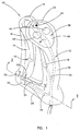
- FIG. 1 is a perspective view of a control device in accordance with the present invention;
- FIG. 2 is a cross-sectional, somewhat schematic, view of one embodiment of the control device along the line 2-2 of FIG. 1;
- FIG. 3 is a schematic, sectional view of one embodiment of the control device along the line 3-3 of FIG. 1;
- FIG. 4 is a perspective view of a second embodiment of a control device, and
- FIG. 5 is a side elevational view of the control device of FIG. 4.
- One embodiment of a
control device 10 is shown in FIG. 1. Thecontrol device 10 includes afirst handle 12, asecond handle 14, aresilient attachment member 16, afirst sensor 18, and asecond sensor 20. Thefirst handle 12 includes ahead 24, anintermediate portion 26 and abase portion 28. Thehead 24 is attached to theresilient attachment member 16. Thesecond handle 14 includes an attachedend 30, which is attached to theresilient attachment member 16. and afree end 32. Thefirst sensor 18 is disposed within theintermediate portion 26 of thefirst handle 12. Similarly, thesecond sensor 20 is disposed within thebase portion 28 of thefirst handle 12. Thefirst sensor 18 and thesecond sensor 20 are connected by wiring 34 to a fluid-supplying machine (not shown). - The
intermediate portion 26 of thefirst handle 12 is preferably designed to fit within an operator's palm (not shown). In one embodiment, thebase portion 28 of thefirst handle 12 extends away from theintermediate portion 26 at approximately a 90° angle. Further, thebase portion 28 includes aslot 36. Theslot 36 extends along an approximately length of thebase portion 28. The relationship of theslot 36 to remaining components of thecontrol device 10 is described in greater detail below. - The
first handle 12 also includes, in one embodiment, asecondary input 38 positioned on thehead 24. Thesecondary input 38 includes afirst button 40, asecond button 42, asignaling device 44, and amembrane 46. Thefirst button 40, thesecond button 42, and thesignaling device 44 are connected by wiring 48 to the fluid-supplying machine (not shown). As described in greater-detail below, thefirst button 40 and thesecond button 42 provide an operator with additional control over the fluid-supplying machine (not shown). For example, thefirst button 40 can be used to initiate the fluid-supplying machine, while thesecond button 42 can be used to change the type of fluid delivered: The signalingdevice 44 preferably indicates activation of the fluid-supplying machine. Finally, themembrane 46 covers thefirst button 40, thesecond button 42, and thesignaling device 44 such that external fluids will not contact thefirst button 40, thesecond button 42, thesignaling device 44, or thewiring 48. - The
second handle 14 is preferably designed to be grasped by the fingers of an operator (not shown). Thesecond handle 14 includes afirst magnet 50 and asecond magnet 52. Thefirst magnet 50 is positioned within an intermediate portion of thesecond handle 14, at the same approximate level as thefirst sensor 18. Thesecond magnet 52 extends outwardly from thefree end 32 of thesecond handle 14. Thesecond magnet 52 is preferably maintained within a cylindrical enclosure such as apin 75 and is sized to move within theslot 36 of thefirst handle 12. - The
resilient attachment member 16 is preferably made from a strong yet flexible material, and assumes a curved shape as shown in FIG.1. With the configuration shown in FIG. 1, theresilient attachment member 16 biases thesecond handle 14 away from thefirst handle 12. More particularly, theresilient attachment member 16 forces thefree end 32 of thesecond handle 14 away from theintermediate portion 26 of thefirst handle 12. - The
first sensor 18 and thesecond sensor 20 are preferably Hall effect sensors. Thefirst sensor 18 is associated with thefirst magnet 50. Hall effect sensors are well known in the art. Basically, thefirst magnet 50 produces a magnetic field perpendicular to thefirst sensor 18. Thefirst sensor 18 generates an output voltage (or Hall voltage) which is proportional to the strength of the magnetic field generated by thefirst magnet 50. As thefirst magnet 50 is positioned closer to thefirst sensor 18, the force of the magnetic field sensed by thefirst sensor 18 increases, thus increasing the voltage produced by thefirst sensor 18. Thus, thefirst sensor 18 can "sense" or respond to a change in the distance between thefirst handle 12 and thesecond handle 14. The signal produced by thefirst sensor 18 is a variable control signal in that the signal varies as a function of the distance between thefirst sensor 18 thefirst magnet 50, and thus between thefirst handle 12 and thesecond handle 14. - The
second sensor 20, in conjunction with thesecond magnet 52, is similar to thefirst sensor 18. In the preferred embodiment, however, thesecond sensor 20 is a simple digital type sensor, generating an on/off signal. Greater details on thesecond sensor 20 are provided below. - The
wiring 34 communicates the control signal generated by the first sensor 18 (and the second sensor 20) to the fluid-supplying machine (not shown). In the preferred embodiment, thewiring 34 is directly connected to the fluid-supplying machine. However, other forms of communication devices are acceptable. For example, thewiring 34 can be replaced with an infra red or r.f. transmitter which transmits the control signal to an appropriate receiver associated with the fluid-supplying machine. - In addition to providing a magnetic field for the
second sensor 20, thesecond magnet 52 serves as a guide for thesecond handle 14. As previously described, thesecond magnet 52 extends outwardly from thefree end 32 of thesecond handle 14. As shown in FIG. 1. thesecond magnet 52 rides within theslot 36 in thebase portion 28. Thus, when thesecond handle 14 is moved with respect to thefirst handle 12, thesecond magnet 52 interacts with theslot 36 to insure that the movement occurs in a relatively planar direction. Further, thepin 75 containing thesecond magnet 52 provides a stop to the biasing action of theresilient attachment member 16. In this regard, thesecond magnet 52 abuts a leading end of theslot 36. In this abutting position, thesecond magnet 52 prevents or stops theflexible attachment member 16 from biasing thesecond handle 14 further away from thefirst handle 12. Further details on the design of theslot 36 are provided below. - Further details on construction of the
control device 10 are depicted in FIG. 2. As shown in FIG. 2, afirst enclosure 54 encapsulates thefirst sensor 18 and thesecond sensor 20. In the preferred embodiment, thefirst enclosure 54 is cast from a thermoset urethane polymer which can withstand thermal, chemical and ultraviolet sterilization methods. Alternatively, any moldable polymer which is capable of withstanding repeated use and adverse environments is acceptable. Thefirst enclosure 54 is sealed and set around aninternal portion 56 of thefirst handle 12. With this construction, thefirst enclosure 54 encapsulates and seals thefirst sensor 18 against theinternal portion 56 of thefirst handle 12. Similarly, thefirst enclosure 54 encapsulates and seals thesecond sensor 20 against theinternal portion 56 of thefirst handle 12. In an alternative embodiment, at least a portion of thefirst sensor 18 is cast or potted into theinternal portion 56 of thefirst handle 12. Thefirst enclosure 54 is then over molded using a thermoplastic injection molded material. Regardless of how it is formed, thefirst enclosure 54 is preferably formed to fit within an operator's hand. - In one embodiment, the
control device 10 includes asecond enclosure 58 which is sealed to and formed about aninternal portion 60 of thesecond handle 14. Similar to thefirst enclosure 54, thesecond enclosure 58 is preferably cast from a thermoset urethane polymer which can withstand thermal, chemical, and ultraviolet sterilization methods. Thesecond enclosure 58 seals thefirst magnet 50 against theinternal portion 60 of thesecond handle 14. In one embodiment, thesecond magnet 52 is sealed within a hollow pin (not shown) which in turn is attached to thesecond handle 14 as shown in FIG. 2. With this configuration, the hollow pin containing thesecond magnet 52 extends downwardly from thefree end 32 of theinternal portion 60 of thesecond handle 14. Thesecond enclosure 58 is formed around the hollow pin/second magnet 52. - Further, the
second enclosure 58 is formed to fit within an operator's fingers. It should be recognized, however, that thesecond enclosure 58 is not a necessary element. Thesecond handle 14 shown in FIG. 2 does not include any electrical components, unlike thefirst handle 12. Thus, there is no concern for protecting electrical components from the environment. Basically then, thesecond enclosure 58 simply provides a uniform appearance to thecontrol device 10, while form fitting thesecond handle 14 to the operator's fingers. Alternatively then, theinternal portion 60 can be manufactured to assume this preferred shape and thesecond enclosure 58 omitted. - While the
first enclosure 54 is shown as encompassing thefirst handle 12, thefirst enclosure 54 need only sealably enclose thefirst sensor 18 and thesecond sensor 20 from the environment. Alternatively then, thefirst sensor 18 and thesecond sensor 20 can be positioned within theinternal portion 56, thus eliminating the need for thefirst enclosure 54. - As shown in FIG. 2, the
internal portion 56 of thefirst handle 12, theresilient attachment member 16 and theinternal portion 60 of thesecond handle 14 are constructed as a uniform body and form a backbone. In the preferred embodiment, the backbone is made from a resinous material such as acetal resin. The resin is hardened through the molding process to provide the requisite resiliency for theresilient attachment member 16. Further, the resin is designed to withstand thermal, chemical, and ultraviolet sterilization methods while yielding excellent fatigue and environment properties. - During use, the
control device 10 is initially in a null position shown in FIGS. 1 and 2. In the null position, theresilient attachment member 16 biases thesecond handle 14 away from thefirst handle 12 such that thesecond magnet 52 abuts the leading end of theslot 36. In the null position, thesecond handle 14 is at a maximum distance from thefirst handle 12. Thus, thefirst magnet 50 is at a maximum distance from thefirst sensor 18. In the null position, thefirst sensor 18 produces a control signal representative of "no flow." In other words, the control signal produced by thefirst sensor 18 is interpreted by the fluid-supplying machine (not shown) as calling for no fluid. - To initiate the fluid flow from the fluid-supplying machine, an operator (not shown) grasps the
control device 10 such that thefirst handle 12 rests in the operator's palm while thesecond handle 14 is held by the operator's fingers The operator supplies an input to thecontrol device 10 by forcing thesecond handle 14 toward thefirst handle 12. In the preferred embodiment, the control device includes a lock which the operator must disengage prior to use. Further details on the lock are provided below. As thesecond handle 14 moves toward thefirst handle 12, the signal produced by thefirst sensor 18 changes in response to the position of thefirst magnet 50. As thesecond handle 14, and thus thefirst magnet 50, is forced toward thefirst sensor 18, thefirst sensor 18 varies the control signal to require increased fluid flow from the fluid-supplying machine (not shown). Thus, thefirst sensor 18 produces a variable control signal as a function of the distance between thefirst handle 12 and thesecond handle 14. As thesecond handle 14 is drawn closer to thefirst handle 12, the control signal generated by thefirst sensor 18 varies, producing a signal representative of increased fluid flow. - To maintain a steady flow of fluid from the fluid-supplying machine (not shown), the operator simply maintains the position of the
second handle 14 with respect to thefirst handle 12. In this control position, thefirst sensor 18 generates a consistent control signal which is interpreted by the fluid-supplying machine as calling for a same fluid flow. - To decrease fluid flow from the fluid-supplying machine (not shown), the operator (not shown) simply increases the distance between the
first handle 12 and thesecond handle 14 by reducing the force applied to thesecond handle 14. Theresilient attachment member 16 biases thesecond handle 14 away from thefirst handle 12. As thesecond handle 14, and thus thefirst magnet 50, moves away from thefirst handle 12, thefirst sensor 18 produces a control signal representative of a reduction in fluid flow to the fluid-supplying machine. Once again, thefirst sensor 18 generates a variable control signal as a function of the distance between thehandle 12 and thesecond handle 14. To stop fluid flow altogether from the fluid-supplying machine, thesecond handle 14 is allowed to be biased by theresilient attachment member 16 to the null position shown in FIGs. 1 and 2. In this position, thefirst sensor 18 produces a signal which the fluid-supplying machine recognizes as calling for no fluid flow. - In the preferred embodiment, the control signal generated by the
first sensor 18 varies proportionately between a pre-set maximum and minimum value as thesecond handle 14, and thus thefirst magnet 50, is moved toward or away from thefirst handle 12. For example, thefirst sensor 18 may produce a control signal representative of a fluid flow of 5 mls/second when thesecond handle 14 is moved one-fourth of the maximum distance toward thefirst handle 12; 10 mls/second at one-half maximum distance; and 15 mls/second at three-fourths maximum distance. However, the control signal generated by thefirst sensor 18 can be utilized by the fluid-supplying machine to call for incrementally different fluid flows. For example, when thesecond handle 14 is moved from the null position to one-fourth of the maximum allowable movement, a signal could be produced representative of 1 ml/second; 10 mls/second at one-half maximum distance; and 50 mls/second at three-fourths maximum distance. Other control signal interpretations are equally acceptable, so long as the control signal generated by thefirst sensor 18 varies as a function of the distance between thefirst handle 12 and thesecond handle 14. - The
second sensor 20 is preferably designed to generate a digital, on/off signal. The digital signal produced by thesecond sensor 20 is used to indicate that thesecond handle 14 is in the null position. When thesecond handle 14, and thus thesecond sensor 20, is in the null position shown in FIG. 2, thesecond sensor 20 supplies a digital signal representative of thecontrol device 10 being in an "off' position. Once thesecond magnet 52 is moved away from thesecond sensor 20, thesecond sensor 20 produces a digital signal indicative of the control device being activated. Thus, thesecond sensor 20 is preferably used to sense whether thesecond handle 14 is in the null or undeflected state. Further, once thesecond handle 14 is maneuvered away from thesecond sensor 20, thesecond sensor 20 signals activation of the fluid-supplying machine (not shown). Thesecond sensor 20 is also used to calibrate thefirst sensor 18, in that the "off" state and "on" state of thesecond sensor 20 can be compared with the signal generated by thefirst sensor 18. It should be understood that thesecond sensor 20 is not a required element in that the necessary variable control signal is provided solely by thefirst sensor 18. If thesecond sensor 20 is eliminated, thesecond magnet 52 can be replaced with a dowel or similar body sized to fit within theslot 36. - The
secondary input 38 is used to provide additional control over the fluid-supplying machine (not shown). The first button (40 in FIG. I) and the second button (42 in FIG. 1) are preferably push buttons which effectuate an on-off control signal. Thefirst button 40 and thesecond button 42 can represent a variety of different control functions. For example, thefirst button 40 can be used to reset the fluid flow process. Thesecond button 42 can be used to call for an alternative fluid to be delivered. Where, for example, the fluid-supplying machine contains both a therapeutic material and a saline solution, thesecond button 42 can be used to switch from one fluid to the other. Finally, thesignaling device 44 signals the operator (not shown) as to the operational status of the fluid-supplying machine. In the preferred embodiment, thesignaling device 44 is a light-emitting diode. Notably, while the preferred embodiment includes thesecondary input 38, it is not a required element. Thecontrol device 10 will control fluid flow equally as well without thesecondary input 38. which simply provides an auxiliary form of control. - As previously described, prior to use, the
control device 10 is maintained in a null position. To avoid accidental activation of thecontrol device 10, theslot 36 is preferably provided with ashoulder 62 as shown in FIG. 3. In the null position, thesecond magnet 52, which as previously described is preferably sealed within a hollow pin, rests within theshoulder 62. When an operator (not shown) attempts to pick up the control device 10 (shown in FIG. 1), the force required to do so will not accidentally or unexpectedly move the second handle 14 (shown in FIG. 1) towards the first handle 12 (shown in FIG. 1) which would otherwise cause activation of the fluid-supplying machine (not shown). To initiate fluid flow, an operator must consciously maneuver the second handle 14 (shown in FIG. 1) such that thesecond magnet 52 moves out from theshoulder 62 and into theslot 36. Once thesecond magnet 52 is maneuvered from theshoulder 62, thesecond sensor 20 signals activation of the fluid-supplying machine. Subsequently, thesecond handle 14 is moved by the operator to control flow rate from the fluid-supplying machine via a signal from the first sensor (18 in FIG. 1). - FIG. 4 illustrates a second embodiment of a hand controller at 100. The function and principles of operation are analogous to the hand controller described in FIGS. 1-3. FIG. 5 schematically shows the
hand controller 100 includingsensors sensors magnets magnets - The control device of the present invention provides a unique apparatus for controlling a fluid-supplying machine. The control device includes a sensor capable of producing a variable control signal representative of a distance between two control handles. This distance is selectively controlled by an operator. Thus, an operator can vary fluid flow from a fluid-supplying machine over a range of possible flow rates by simply varying the position of the two handles with respect to one another. This variable control feature is unique over known prior art control devices. Further, in the preferred embodiment, an enclosure seals the sensor from the environment. Thus, the control device can be used in a variety of applications where the work environment involves corrosive fluids. Even further, because of the enclosure, the control device can be sterilized between uses without damaging the sensor. This feature is extremely important with medical applications where repeated sterilization is required.
- Although the present invention has been described with reference to preferred embodiment, workers skilled in the art will recognize that changes may be made in form and detail without departing from the scope of protection as defined by the claims. For example, the resilient attachment member has been preferably described as being a curved, resinous body. However, the resilient attachment member can assume a variety of forms and materials. For example, the resilient attachment member can be a metallic spring. Other approaches are equally acceptable so long as the resilient attachment member biases the first handle to a known position with respect to the second handle.
- Similarly, the preferred design may be altered to provide for an adjustable spring rate of the resilient attachment member. This is accomplished by configuring the second enclosure (58 in FIG. 2) to be selectively positioned along the second handle (14 in FIG. 2) by the user. Thus, the user could change the effective beam length, and thus the spring rate, to whatever level is desired.
- The sensors have been preferably described as being Hall effect devices. However, other sensors such as strain gauges, RVDTs and optical encoders having the ability to produce a signal related to the distance between the first handle and the second handle are also acceptable. Similarly, a pressure sensor can be used to produce a variable control signal that is proportional to the compressive force applied by an operator. Additionally, the
control device 10 can include a dynamic actuator whereby feedback is supplied to the flexible attachment member to increase or decrease the opposition force generated by the flexible attachment member in response to an increase or decrease in pressure of the fluid being delivered. - Finally, the first handle and the second handle have been described as preferably being elongated members of approximately equal length, sized to fit within an operator's hand. Other designs are acceptable. For example, the control device can assume the shape of a hand gun. With this embodiment, the first handle would be a stock and the second would be a trigger. Similar approaches can be utilized so long as an operator is provided with two "handles" which are movable with respect to one another so that the operator can change the position of one handle with respect to the other handle. This change in position is sensed by a sensor which in turn generates a variable control signal.
Claims (28)
- A control device (10) for use in the biomedical, chemical or food processing industries wherein the device controls a fluid-supplying machine, the device comprising:a first control surface (12);a second control surface (14);biasing means (16) connecting a portion of the first control surface to a portion of the second control surface, wherein the biasing means is configured to bias the first control surface to a known position with respect to the second control surface; andsensing means (18) operatively associated with one of the first control surface or the second control surface, characterised in that the sensing means (18) is produces a variable control signal indicative of a position of the first control surface with respect to the second control surface.
- The device (10) of Claim 1, further comprising:communication means (34) connected to the sensing means (18) for communicating the variable control signal from the sensing means to the fluid-supplying machine.
- The device (10) of Claim 1, further comprising:an enclosure (54) sealing the sensing means (18) such that external fluids cannot contact the sensing means.
- The device (10) of Claim 1, wherein the sensing means (18) includes a Hall effect sensor attached to the first control surface (12) and a magnetic means (50, 52) associated with the second control surface (14).
- The device (10) of Claim 1, wherein the first control surface (12) and the second control surface (14) are configured to receive an input from an operator, and further wherein the sensing means (18) is configured to alter the variable control signal in response to the input.
- The device (10) of Claim 5, wherein the biasing means (16) is configured to oppose the input placed on the first control surface (12) and the second control surface (14).
- The device (10) of any preceding claim wherein the first control surface is part of a first handle (12);
the second control surface is part of a second handle (14);
the biasing means is a resilient attachment member (16) connecting the first handle to the second handle such that an operator can select a distance between the first handle and second handle; and the sensing means is
a first sensor (18) operatively associated with one of the first handle or the second handle for generating the control signal as a function of said distance between the first handle and second handle. - The device (10) of Claim 7, further comprising:a communication device connected to the first sensor (18) for communicating the control signal from the first sensor to the fluid-supplying machine.
- The device (10) of Claim 7, further comprising:an enclosure (54) sealing the first sensor (18) to one of the first handle (12) or second handle (14) such that external fluids cannot contact the first sensor.
- The device (10) of Claim 9, wherein the enclosure (54) is a polymer material.
- The device (10) of Claim 9, wherein the first handle (12) includes a head portion (24), an intermediate portion (26), and a base portion (28), and further wherein the enclosure (54) encompasses the intermediate portion of the first handle and is configured to be hand held.
- The device (10) of Claim 7, wherein the first sensor (18) is a Hall sensor, the device further comprising:a magnetic body (50) attached to the second handle (14) for producing a magnetic field sensed by the first sensor.
- The device (10) of Claim 12, wherein the first handle (12) includes a head portion (24) connected to the resilient attachment member (16), an intermediate portion (26), and a base (28), wherein the second handle (14) includes a connecting end (30) connected to the resilient attachment member and a free end (32), and further wherein the first sensor (18) and the magnetic body (50) are positioned such that as the free end of the second handle is moved with respect to the intermediate portion of the second handle, the magnetic body moves with respect to the first sensor.
- The device (10) of Claim 7, further comprising:a signaling device disposed on the first handle (12) for indicating status information about a fluid-supplying machine.
- The device (10) of Claim 7, wherein the resilient attachment member (16) is formed from a resinous material.
- The device (10) of Claim 7, wherein the resilient attachment member (16) is a curved body.
- The device (10) of Claim 7, wherein the resilient attachment member (16) is configured to maintain the first handle (12) and the second handle (14) in a null position when not receiving an input from an operator and further such that an operator can move the first handle and the second handle to a command position, and wherein the first sensor (18) produces a signal related to a distance between the null position and the command position.
- The device (10) of Claim 17, where the resilient attachment member (16) is configured to bias the first handle (12) and the second handle (14) from the command position to the null position.
- The device (10) of Claim 7, wherein the first handle (12) includes a head (24) and a base (28), and wherein the second handle (14) includes a connecting end (30) and a free end (32), and further wherein the base includes a slot (36) for receiving the free end of the second handle.
- The device (10) of Claim 19, wherein the slot (36) in the first handle (12) includes a shoulder (62) for selectively maintaining the free end of the second handle.
- The device (10) of Claim 7, further comprising:a secondary input device (38) associated with the first handle (14) for receiving an operational input from an operator related to operation of the fluid-supplying machine.
- The device (10) of Claim 21, wherein the secondary input device (38) is a keypad (40, 42) covered by a membrane (46).
- The device (10) of Claim 1, wherein the biasing means (16) is a resilient attachment member, such that an operator can select a distance between the first control surface and the second control surface.
- The device (10) of Claim 23, wherein the resilient attachment member is formed from resinous material.
- The device (10) of Claim 24, wherein the resilient attachment member is a curved body.
- The device (10) of Claim 23 wherein the resilient attachment member is a spring.
- The device (10) of Claim 1 wherein the sensing means includes an optical encoder.
- The device (10) of Claim 1 wherein the control device is configured to fit within the palm of a hand such that the device may be operated with one hand.
Priority Applications (1)
| Application Number | Priority Date | Filing Date | Title |
|---|---|---|---|
| EP05075949.7A EP1571519B1 (en) | 1997-10-10 | 1998-10-09 | Control device for providing a variable control signal to a fluid-supplying machine |
Applications Claiming Priority (3)
| Application Number | Priority Date | Filing Date | Title |
|---|---|---|---|
| US948856 | 1997-10-10 | ||
| US08/948,856 US5988587A (en) | 1997-10-10 | 1997-10-10 | Control device for providing a variable control signal to a fluid-supplying machine |
| PCT/US1998/021396 WO1999019892A1 (en) | 1997-10-10 | 1998-10-09 | Control device for providing a variable control signal to a fluid-supplying machine |
Related Child Applications (1)
| Application Number | Title | Priority Date | Filing Date |
|---|---|---|---|
| EP05075949.7A Division EP1571519B1 (en) | 1997-10-10 | 1998-10-09 | Control device for providing a variable control signal to a fluid-supplying machine |
Publications (2)
| Publication Number | Publication Date |
|---|---|
| EP1021813A1 EP1021813A1 (en) | 2000-07-26 |
| EP1021813B1 true EP1021813B1 (en) | 2006-01-18 |
Family
ID=25488322
Family Applications (2)
| Application Number | Title | Priority Date | Filing Date |
|---|---|---|---|
| EP98953373A Expired - Lifetime EP1021813B1 (en) | 1997-10-10 | 1998-10-09 | Control device for providing a variable control signal to a fluid-supplying machine |
| EP05075949.7A Expired - Lifetime EP1571519B1 (en) | 1997-10-10 | 1998-10-09 | Control device for providing a variable control signal to a fluid-supplying machine |
Family Applications After (1)
| Application Number | Title | Priority Date | Filing Date |
|---|---|---|---|
| EP05075949.7A Expired - Lifetime EP1571519B1 (en) | 1997-10-10 | 1998-10-09 | Control device for providing a variable control signal to a fluid-supplying machine |
Country Status (8)
| Country | Link |
|---|---|
| US (1) | US5988587A (en) |
| EP (2) | EP1021813B1 (en) |
| JP (1) | JP4315592B2 (en) |
| AT (1) | ATE316292T1 (en) |
| CA (1) | CA2308542C (en) |
| DE (1) | DE69833269T2 (en) |
| ES (1) | ES2260853T3 (en) |
| WO (1) | WO1999019892A1 (en) |
Cited By (1)
| Publication number | Priority date | Publication date | Assignee | Title |
|---|---|---|---|---|
| US8945051B2 (en) | 2009-07-24 | 2015-02-03 | Bayer Medical Care Inc. | Multi-fluid medical injector system and methods of operation |
Families Citing this family (43)
| Publication number | Priority date | Publication date | Assignee | Title |
|---|---|---|---|---|
| DE69432582T2 (en) | 1993-10-28 | 2003-11-27 | Medrad, Inc. | System for the administration of liquids in several patients |
| EP0650739B1 (en) | 1993-10-28 | 2003-02-26 | Medrad, Inc. | Total system for contrast delivery |
| US5840026A (en) | 1994-09-21 | 1998-11-24 | Medrad, Inc. | Patient specific dosing contrast delivery systems and methods |
| US6673048B1 (en) | 2000-05-24 | 2004-01-06 | Acist Medical Systems, Inc. | Pressure sleeve assembly |
| US7094216B2 (en) | 2000-10-18 | 2006-08-22 | Medrad, Inc. | Injection system having a pressure isolation mechanism and/or a handheld controller |
| US7566320B2 (en) | 2001-02-14 | 2009-07-28 | Acist Medical Systems, Inc. | Fluid injector system |
| US6699232B2 (en) * | 2001-03-01 | 2004-03-02 | Scimed Life Systems, Inc. | Fluid injection apparatus with improved contrast visualization |
| US7044933B2 (en) * | 2001-03-01 | 2006-05-16 | Scimed Life Systems, Inc. | Fluid injection system for coronary intervention |
| US6834842B2 (en) * | 2002-01-09 | 2004-12-28 | Scimed Life Systems, Inc. | Fluid management valve |
| US9956377B2 (en) | 2002-09-20 | 2018-05-01 | Angiodynamics, Inc. | Method and apparatus for intra-aortic substance delivery to a branch vessel |
| EP1653493A4 (en) * | 2003-03-26 | 2008-04-30 | Ken Takachi | Variable hand switch |
| JP4374447B2 (en) | 2003-12-25 | 2009-12-02 | 独立行政法人産業技術総合研究所 | Method for analyzing the interaction between protein and sugar chain |
| US7879008B2 (en) * | 2004-04-08 | 2011-02-01 | Medrad, Inc. | Control device for a fluid delivery system |
| JP2008520287A (en) | 2004-11-16 | 2008-06-19 | メドラッド インコーポレーテッド | System and method for determining patient transfer function for drug infusion and modeling patient response |
| HUE034171T2 (en) | 2004-11-24 | 2018-02-28 | Bayer Healthcare Llc | Devices, systems and methods for fluid delivery |
| US9011377B2 (en) | 2008-11-05 | 2015-04-21 | Bayer Medical Care Inc. | Fluid mixing control device for a multi-fluid delivery system |
| US9433730B2 (en) | 2013-03-14 | 2016-09-06 | Bayer Healthcare Llc | Fluid mixing control device for a multi-fluid delivery system |
| JP4565237B2 (en) | 2005-06-23 | 2010-10-20 | 独立行政法人産業技術総合研究所 | Sugar chain or complex carbohydrate analyzer |
| US8597576B2 (en) | 2005-06-23 | 2013-12-03 | National Institute Of Advanced Industrial Science And Technology | Analyzer for glycan or complex carbohydrate |
| FR2903204B1 (en) * | 2006-06-30 | 2011-01-21 | Noremat | "DEVICE FORMING ADJUSTABLE SUPPORT FOR MANUAL CONTROL" |
| WO2008085421A2 (en) | 2006-12-29 | 2008-07-17 | Medrad, Inc. | Patient-based parameter generation systems for medical injection procedures |
| JP5437240B2 (en) | 2007-07-17 | 2014-03-12 | メドラッド インコーポレーテッド | Apparatus, system and method for determining parameters of cardiopulmonary function evaluation and fluid delivery procedures |
| US9421330B2 (en) | 2008-11-03 | 2016-08-23 | Bayer Healthcare Llc | Mitigation of contrast-induced nephropathy |
| US20100331879A1 (en) * | 2009-06-25 | 2010-12-30 | The Curators Of The University Of Missouri | Articulating Surgical Hand Tool |
| JP6025718B2 (en) | 2010-06-24 | 2016-11-16 | ベイヤー メディカル ケア インク. | A model for drug propagation and parameter generation for infusion protocols |
| HK1199851A1 (en) | 2011-09-21 | 2015-07-24 | Bayer Healthcare Llc | Continuous multi-fluid pump device, drive and actuating system and method |
| EP2850418B1 (en) | 2012-05-14 | 2019-02-20 | Bayer Healthcare LLC | Systems and methods for determination of pharmaceutical fluid injection protocols based on x-ray tube voltage |
| WO2014047626A2 (en) | 2012-09-24 | 2014-03-27 | Angiodynamics, Inc. | Power injector device and method of use |
| US11369739B2 (en) | 2013-01-21 | 2022-06-28 | Medline Industries, Lp | Method to provide injection system parameters for injecting fluid into patient |
| US9555379B2 (en) | 2013-03-13 | 2017-01-31 | Bayer Healthcare Llc | Fluid path set with turbulent mixing chamber, backflow compensator |
| RU2714926C2 (en) | 2015-01-09 | 2020-02-21 | БАЙЕР ХелсКер ЛЛСи | Multiple fluid delivery system with multi-use disposable set and features thereof |
| USD850235S1 (en) * | 2016-02-25 | 2019-06-04 | Southco, Inc. | Actuator knob for rod and tube assembly |
| US10898638B2 (en) | 2016-03-03 | 2021-01-26 | Bayer Healthcare Llc | System and method for improved fluid delivery in multi-fluid injector systems |
| US12263326B2 (en) | 2016-11-14 | 2025-04-01 | Bayer Healthcare Llc | Methods and systems for verifying the contents of a syringe used for medical fluid delivery |
| DE202017100925U1 (en) | 2017-02-20 | 2018-05-24 | Hans Heidolph GmbH | Operating element for a laboratory device |
| CA3068739A1 (en) | 2017-08-31 | 2019-03-07 | Bayer Healthcare Llc | Fluid path impedance assessment for improving fluid delivery performance |
| EP3675929B1 (en) | 2017-08-31 | 2026-05-13 | Bayer Healthcare LLC | Method for dynamic pressure control in a fluid injector system |
| US11786652B2 (en) | 2017-08-31 | 2023-10-17 | Bayer Healthcare Llc | System and method for drive member position and fluid injector system mechanical calibration |
| EP3675931B1 (en) | 2017-08-31 | 2021-08-11 | Bayer Healthcare LLC | Injector pressure calibration system and method |
| US11478581B2 (en) | 2017-08-31 | 2022-10-25 | Bayer Healthcare Llc | Fluid injector system volume compensation system and method |
| CN116966369A (en) | 2018-04-19 | 2023-10-31 | 拜耳医药保健有限公司 | System and method for air detection in a fluid injector |
| CN112823031B (en) | 2018-08-28 | 2023-08-15 | 拜耳医药保健有限责任公司 | Fluid injector system, method and computer program product for preventing fluid backflow |
| CA3111209A1 (en) | 2018-08-28 | 2020-03-05 | Bayer Healthcare Llc | Fluid injector system with improved ratio performance |
Family Cites Families (6)
| Publication number | Priority date | Publication date | Assignee | Title |
|---|---|---|---|---|
| US4380704A (en) * | 1980-04-28 | 1983-04-19 | Wisda Michael S | Electrical switch |
| US4593858A (en) * | 1985-04-01 | 1986-06-10 | Butterworth, Inc. | Fail-safe high pressure fluid delivery system |
| US4829844A (en) * | 1987-11-25 | 1989-05-16 | General Electric Company | Power assist handle |
| GB2247161A (en) * | 1990-08-22 | 1992-02-26 | Shaun Waddingham | Electrical trigger control of water jet |
| US5589828A (en) * | 1992-03-05 | 1996-12-31 | Armstrong; Brad A. | 6 Degrees of freedom controller with capability of tactile feedback |
| DE69306941T2 (en) * | 1992-03-25 | 1997-05-28 | Penny & Giles Blackwood Ltd | STICKS. |
-
1997
- 1997-10-10 US US08/948,856 patent/US5988587A/en not_active Expired - Lifetime
-
1998
- 1998-10-09 DE DE69833269T patent/DE69833269T2/en not_active Expired - Lifetime
- 1998-10-09 JP JP2000516363A patent/JP4315592B2/en not_active Expired - Fee Related
- 1998-10-09 ES ES98953373T patent/ES2260853T3/en not_active Expired - Lifetime
- 1998-10-09 EP EP98953373A patent/EP1021813B1/en not_active Expired - Lifetime
- 1998-10-09 AT AT98953373T patent/ATE316292T1/en active
- 1998-10-09 WO PCT/US1998/021396 patent/WO1999019892A1/en not_active Ceased
- 1998-10-09 CA CA002308542A patent/CA2308542C/en not_active Expired - Lifetime
- 1998-10-09 EP EP05075949.7A patent/EP1571519B1/en not_active Expired - Lifetime
Cited By (4)
| Publication number | Priority date | Publication date | Assignee | Title |
|---|---|---|---|---|
| US8945051B2 (en) | 2009-07-24 | 2015-02-03 | Bayer Medical Care Inc. | Multi-fluid medical injector system and methods of operation |
| US9474857B2 (en) | 2009-07-24 | 2016-10-25 | Bayer Healthcare Llc | Multi-fluid medical injector system and methods of operation |
| US10751465B2 (en) | 2009-07-24 | 2020-08-25 | Bayer Healthcare Llc | Multi-fluid medical injector system and methods of operation |
| US12285587B2 (en) | 2009-07-24 | 2025-04-29 | Bayer Healthcare Llc | Multi-fluid medical injector system and methods of operation |
Also Published As
| Publication number | Publication date |
|---|---|
| DE69833269D1 (en) | 2006-04-06 |
| ES2260853T3 (en) | 2006-11-01 |
| WO1999019892A1 (en) | 1999-04-22 |
| WO1999019892A8 (en) | 1999-07-08 |
| CA2308542C (en) | 2007-04-24 |
| EP1571519A3 (en) | 2009-09-09 |
| JP2001520104A (en) | 2001-10-30 |
| JP4315592B2 (en) | 2009-08-19 |
| WO1999019892B1 (en) | 1999-06-03 |
| DE69833269T2 (en) | 2006-11-02 |
| EP1571519B1 (en) | 2014-01-08 |
| ATE316292T1 (en) | 2006-02-15 |
| US5988587A (en) | 1999-11-23 |
| CA2308542A1 (en) | 1999-04-22 |
| EP1571519A2 (en) | 2005-09-07 |
| EP1021813A1 (en) | 2000-07-26 |
Similar Documents
| Publication | Publication Date | Title |
|---|---|---|
| EP1571519B1 (en) | Control device for providing a variable control signal to a fluid-supplying machine | |
| US4162042A (en) | Spray gun safety sensor | |
| US4730861A (en) | Finger gripper with state indicator | |
| US5654885A (en) | Valve position controller | |
| EP1295187B1 (en) | Plug and seat positioning system for control applications | |
| CN109789557B (en) | Control device and control method for an industrial machine having a controlled motion drive | |
| US20120273701A1 (en) | Ergonomic Pneumatic Deadman Valve | |
| US4957274A (en) | Position sensor for a rotary valve | |
| EP1318341A2 (en) | Flow rate control apparatus | |
| WO1998024017A3 (en) | Control means | |
| ATE320889T1 (en) | WATER JET CUTTING MACHINE WITH NON-CONTACT AND OPTIONAL TACTILE DISTANCE GUIDANCE SENSOR DEVICE | |
| CA2167431A1 (en) | Two wire position sense and control of modulating gas valve or other electromechanical actuators | |
| WO2001042693A3 (en) | Pressure relief valve detection and monitoring device and system | |
| EP3908899B1 (en) | A joystick with increased endurance | |
| US4507601A (en) | Lever stroke control | |
| EP0368322A3 (en) | Control lever apparatus and actuator operation apparatus | |
| US8288670B2 (en) | Electric deadman switch for blast system | |
| JP3704163B2 (en) | Vacuum supply unit | |
| US4309582A (en) | Push button switch for a controller | |
| US20190270206A1 (en) | Control device and control method for industrial machines with controlled motion drives | |
| IL123800A (en) | Flow limiter | |
| US5425529A (en) | Pneumatic membrane switches and switch assembly | |
| EP4663016A1 (en) | Knapsack sprayer | |
| US4322590A (en) | Pneumatic remote sensing apparatus | |
| WO1996026044A3 (en) | Material handling |
Legal Events
| Date | Code | Title | Description |
|---|---|---|---|
| PUAI | Public reference made under article 153(3) epc to a published international application that has entered the european phase |
Free format text: ORIGINAL CODE: 0009012 |
|
| 17P | Request for examination filed |
Effective date: 20000414 |
|
| AK | Designated contracting states |
Kind code of ref document: A1 Designated state(s): AT BE CH DE DK ES FI FR GB GR IE IT LI LU NL PT SE |
|
| RIN1 | Information on inventor provided before grant (corrected) |
Inventor name: COPA, VINCE Inventor name: DUCHON, DOUG |
|
| RAP1 | Party data changed (applicant data changed or rights of an application transferred) |
Owner name: ACIST MEDICAL SYSTEMS, INC. |
|
| 17Q | First examination report despatched |
Effective date: 20030402 |
|
| GRAP | Despatch of communication of intention to grant a patent |
Free format text: ORIGINAL CODE: EPIDOSNIGR1 |
|
| GRAS | Grant fee paid |
Free format text: ORIGINAL CODE: EPIDOSNIGR3 |
|
| RIN1 | Information on inventor provided before grant (corrected) |
Inventor name: COPA, VINCE Inventor name: DUCHON, DOUG |
|
| RAP1 | Party data changed (applicant data changed or rights of an application transferred) |
Owner name: ACIST MEDICAL SYSTEMS, INC. |
|
| GRAA | (expected) grant |
Free format text: ORIGINAL CODE: 0009210 |
|
| AK | Designated contracting states |
Kind code of ref document: B1 Designated state(s): AT BE CH DE DK ES FI FR GB GR IE IT LI LU NL PT SE |
|
| PG25 | Lapsed in a contracting state [announced via postgrant information from national office to epo] |
Ref country code: NL Free format text: LAPSE BECAUSE OF FAILURE TO SUBMIT A TRANSLATION OF THE DESCRIPTION OR TO PAY THE FEE WITHIN THE PRESCRIBED TIME-LIMIT Effective date: 20060118 Ref country code: IT Free format text: LAPSE BECAUSE OF FAILURE TO SUBMIT A TRANSLATION OF THE DESCRIPTION OR TO PAY THE FEE WITHIN THE PRESCRIBED TIME-LIMIT;WARNING: LAPSES OF ITALIAN PATENTS WITH EFFECTIVE DATE BEFORE 2007 MAY HAVE OCCURRED AT ANY TIME BEFORE 2007. THE CORRECT EFFECTIVE DATE MAY BE DIFFERENT FROM THE ONE RECORDED. Effective date: 20060118 Ref country code: FI Free format text: LAPSE BECAUSE OF FAILURE TO SUBMIT A TRANSLATION OF THE DESCRIPTION OR TO PAY THE FEE WITHIN THE PRESCRIBED TIME-LIMIT Effective date: 20060118 Ref country code: BE Free format text: LAPSE BECAUSE OF FAILURE TO SUBMIT A TRANSLATION OF THE DESCRIPTION OR TO PAY THE FEE WITHIN THE PRESCRIBED TIME-LIMIT Effective date: 20060118 |
|
| REG | Reference to a national code |
Ref country code: GB Ref legal event code: FG4D |
|
| REG | Reference to a national code |
Ref country code: CH Ref legal event code: EP |
|
| REG | Reference to a national code |
Ref country code: IE Ref legal event code: FG4D |
|
| REF | Corresponds to: |
Ref document number: 69833269 Country of ref document: DE Date of ref document: 20060406 Kind code of ref document: P |
|
| REG | Reference to a national code |
Ref country code: CH Ref legal event code: NV Representative=s name: KIRKER & CIE SA |
|
| PG25 | Lapsed in a contracting state [announced via postgrant information from national office to epo] |
Ref country code: SE Free format text: LAPSE BECAUSE OF FAILURE TO SUBMIT A TRANSLATION OF THE DESCRIPTION OR TO PAY THE FEE WITHIN THE PRESCRIBED TIME-LIMIT Effective date: 20060418 Ref country code: DK Free format text: LAPSE BECAUSE OF FAILURE TO SUBMIT A TRANSLATION OF THE DESCRIPTION OR TO PAY THE FEE WITHIN THE PRESCRIBED TIME-LIMIT Effective date: 20060418 |
|
| PG25 | Lapsed in a contracting state [announced via postgrant information from national office to epo] |
Ref country code: PT Free format text: LAPSE BECAUSE OF FAILURE TO SUBMIT A TRANSLATION OF THE DESCRIPTION OR TO PAY THE FEE WITHIN THE PRESCRIBED TIME-LIMIT Effective date: 20060619 |
|
| NLV1 | Nl: lapsed or annulled due to failure to fulfill the requirements of art. 29p and 29m of the patents act | ||
| ET | Fr: translation filed | ||
| PG25 | Lapsed in a contracting state [announced via postgrant information from national office to epo] |
Ref country code: IE Free format text: LAPSE BECAUSE OF NON-PAYMENT OF DUE FEES Effective date: 20061009 |
|
| REG | Reference to a national code |
Ref country code: ES Ref legal event code: FG2A Ref document number: 2260853 Country of ref document: ES Kind code of ref document: T3 |
|
| PLBE | No opposition filed within time limit |
Free format text: ORIGINAL CODE: 0009261 |
|
| STAA | Information on the status of an ep patent application or granted ep patent |
Free format text: STATUS: NO OPPOSITION FILED WITHIN TIME LIMIT |
|
| 26N | No opposition filed |
Effective date: 20061019 |
|
| PG25 | Lapsed in a contracting state [announced via postgrant information from national office to epo] |
Ref country code: GR Free format text: LAPSE BECAUSE OF FAILURE TO SUBMIT A TRANSLATION OF THE DESCRIPTION OR TO PAY THE FEE WITHIN THE PRESCRIBED TIME-LIMIT Effective date: 20060419 |
|
| PG25 | Lapsed in a contracting state [announced via postgrant information from national office to epo] |
Ref country code: LU Free format text: LAPSE BECAUSE OF NON-PAYMENT OF DUE FEES Effective date: 20061009 |
|
| REG | Reference to a national code |
Ref country code: FR Ref legal event code: PLFP Year of fee payment: 18 |
|
| REG | Reference to a national code |
Ref country code: FR Ref legal event code: PLFP Year of fee payment: 19 |
|
| REG | Reference to a national code |
Ref country code: FR Ref legal event code: PLFP Year of fee payment: 20 |
|
| PGFP | Annual fee paid to national office [announced via postgrant information from national office to epo] |
Ref country code: FR Payment date: 20171025 Year of fee payment: 20 Ref country code: DE Payment date: 20171027 Year of fee payment: 20 |
|
| PGFP | Annual fee paid to national office [announced via postgrant information from national office to epo] |
Ref country code: GB Payment date: 20171027 Year of fee payment: 20 Ref country code: IT Payment date: 20171024 Year of fee payment: 20 Ref country code: ES Payment date: 20171102 Year of fee payment: 20 Ref country code: CH Payment date: 20171027 Year of fee payment: 20 Ref country code: AT Payment date: 20170920 Year of fee payment: 20 |
|
| REG | Reference to a national code |
Ref country code: DE Ref legal event code: R071 Ref document number: 69833269 Country of ref document: DE |
|
| REG | Reference to a national code |
Ref country code: CH Ref legal event code: PL |
|
| REG | Reference to a national code |
Ref country code: GB Ref legal event code: PE20 Expiry date: 20181008 |
|
| REG | Reference to a national code |
Ref country code: AT Ref legal event code: MK07 Ref document number: 316292 Country of ref document: AT Kind code of ref document: T Effective date: 20181009 |
|
| PG25 | Lapsed in a contracting state [announced via postgrant information from national office to epo] |
Ref country code: GB Free format text: LAPSE BECAUSE OF EXPIRATION OF PROTECTION Effective date: 20181008 |
|
| REG | Reference to a national code |
Ref country code: ES Ref legal event code: FD2A Effective date: 20201204 |
|
| PG25 | Lapsed in a contracting state [announced via postgrant information from national office to epo] |
Ref country code: ES Free format text: LAPSE BECAUSE OF EXPIRATION OF PROTECTION Effective date: 20181010 |