EP1021068B1 - Microwave defrosting method - Google Patents
Microwave defrosting method Download PDFInfo
- Publication number
- EP1021068B1 EP1021068B1 EP00300261A EP00300261A EP1021068B1 EP 1021068 B1 EP1021068 B1 EP 1021068B1 EP 00300261 A EP00300261 A EP 00300261A EP 00300261 A EP00300261 A EP 00300261A EP 1021068 B1 EP1021068 B1 EP 1021068B1
- Authority
- EP
- European Patent Office
- Prior art keywords
- magnetron
- period
- power
- microcomputer
- output data
- Prior art date
- Legal status (The legal status is an assumption and is not a legal conclusion. Google has not performed a legal analysis and makes no representation as to the accuracy of the status listed.)
- Expired - Lifetime
Links
Images


Classifications
-
- F—MECHANICAL ENGINEERING; LIGHTING; HEATING; WEAPONS; BLASTING
- F24—HEATING; RANGES; VENTILATING
- F24C—DOMESTIC STOVES OR RANGES ; DETAILS OF DOMESTIC STOVES OR RANGES, OF GENERAL APPLICATION
- F24C7/00—Stoves or ranges heated by electric energy
- F24C7/08—Arrangement or mounting of control or safety devices
-
- H—ELECTRICITY
- H05—ELECTRIC TECHNIQUES NOT OTHERWISE PROVIDED FOR
- H05B—ELECTRIC HEATING; ELECTRIC LIGHT SOURCES NOT OTHERWISE PROVIDED FOR; CIRCUIT ARRANGEMENTS FOR ELECTRIC LIGHT SOURCES, IN GENERAL
- H05B6/00—Heating by electric, magnetic or electromagnetic fields
- H05B6/64—Heating using microwaves
- H05B6/66—Circuits
- H05B6/68—Circuits for monitoring or control
- H05B6/687—Circuits for monitoring or control for cooking
Definitions
- the present invention relates to a method of operating a microwave oven to defrost an item.
- Microwave ovens are well known and are used to cook food by irradiating it with microwaves.
- the microwaves cause water molecules in the food to vibrate thereby raising the temperature of the food.
- Microwave ovens are usually provided with a defrosting function for defrosting frozen food.
- a defrosting function for defrosting frozen food.
- the frozen food is placed in a cooking chamber of the microwave oven and weight of the food is input.
- a controller part of the microwave oven adjusts the output power of the oven's magnetron in dependence on the input weight.
- the controller part of the microwave oven drives the magnetron for the input time with a corresponding magnetron power output level.
- the user When the user inputs the defrosting time, the user usually sets the defrosting time by guesswork, preference, or based on past experience. Consequently, optimal defrosting is rarely achieved.
- defrosting is performed using a constant power level and is not controlled in dependence on the state of the food being defrosted during the defrosting process. This means that the user must open the oven's door to inspect the food to determine how the defrosting is progressing and adjust the defrosting time as the user deems necessary.
- a method according to the present invention is characterised by:-
- the microwave energy applied may be controlled in dependence on the change in said parameter across one interval.
- the microwave energy applied is controlled in dependence on the changes, if any, in said parameter over a plurality of intervals.
- the method preferably includes determining the time and value differences between a minimum and a maximum for said parameter, wherein the microwave energy applied is controlled in dependence on said differences, and/or determining the substantial absence of change in said parameter over a predetermined plurality of said intervals and terminating the application of microwave energy in response thereto.
- microwave oven configured to operate according to a method according to the present invention.
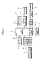
- a microwave oven includes a key input section 2, a door position detection switching section 4, a cooking status detection sensor 6, e.g. a standing wave sensor in the oven's waveguide, a voltage detecting section 8, a status data memory 10, a microcomputer 12 having a memory 12A, a high voltage power circuit 14, a magnetron driving circuit 16, a magnetron 18, a motor driving section 20, a turntable motor 22, and a turntable 24.
- the key input section 2 includes a plurality of cooking item buttons for set various cooking conditions, a cooking start button and a defrosting start button.
- the door position detection switching section 4 detects whether the oven's cooking chamber door is open or closed and generates a corresponding door position signal.
- the cooking status detecting sensor 6 employs an antenna disposed in a waveguide of the microwave oven for detecting the magnetic field of the standing wave in the waveguide formed by the superposition of the forward wave from the magnetron 18 and the reflected wave from the defrosting food.
- the antenna is as disclosed KR-A-98-161026 and KR-U-99-143508.
- the cooking status detecting sensor 6 may include a plurality of sensors such as infrared sensors and temperature sensors for detecting the temperature of food, humidity sensors and gas sensors for detecting water vapour and gas from the food, light emitting and receiving elements for detecting the shape of the food, etc..
- the voltage detecting section 8 accurately detects voltage signals from the cooking status detecting sensor 6. If the cooking status detecting sensor 6 is an antenna, the voltage detecting section 8 includes a diode for rectifying the output voltage of the antenna, a smoothing capacitor for smoothing the rectified voltage and a resistor.
- the status data memory 10 is used to store the defrosting status detecting data which is a result of regularly sampling the output of the cooking status detecting sensor 6 and values calculated therefrom.
- the microcomputer 12 drives the magnetron 18 at a power level appropriate for the food being defrosted and rotates the turntable 24, which carries the food, a predetermined speed.
- one turntable rotation period means a predetermined number of turntable revolutions.
- the microcomputer 12 receives data from the cooking status detecting sensor 6.
- the microcomputer 12 calculates the difference between the data for the present turntable rotation period and a previous one and adjusts the magnetron output power accordingly.
- the memory 12A stores a control program controlling the microcomputer 12 for adjusting the magnetron power level for the defrosting function and for processing the defrosting status detect data obtained from the cooking status detecting sensor 6.
- the magnetron driving circuit 16 receives high-voltage power from the high-voltage power circuit 14 to drive the magnetron 18.
- the motor driving section 20 controlled by the microcomputer 12 to drive the turntable motor 22 to rotate the turntable 24 at the predetermined speed.
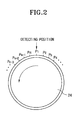
- the microcomputer 12 collects the voltage signals which are output by the cooking status detecting sensor 6 when the turntable 24 is at a plurality of detecting positions (P 1 , P 2 , P 3 , P 4 , ..., P n-3 , P n-2 , P n-1 , P n ) on the regular basis when the magnetron 18 is on.
- the microcomputer 12 sets three rotations of the turntable 24 (T1, T2, T3; See Figure 3) as one turntable rotation period and cycles the magnetron 18 on and off once in each turntable rotation period, i.e., during every three revolutions of the turntable 24.
- One rotation of the turntable 24 takes 10 seconds, and accordingly, the speed of the turntable 24 is 6 rpm.
- the microcomputer 12 operates the magnetron 18 during a portion of the turntable rotation period, which comprises three revolutions T1, T2, T3 of the turntable 24. While the magnetron 18 is on, the microcomputer 12 samples the voltage signals from the cooking status detecting sensor 6 at positions P 1 , P 2 , P 3 , P 4 , ..., P n-3 , P n-2 , P n-1 , P n of the turntable 24.
- the microcomputer 12 calculates the difference between the data obtained from the present turntable rotation period and that from a previous turntable rotation period, and adjusts the magnetron power-on period for the next turntable rotation period in accordance with the calculated difference.
- the magnetron power-on period is gradually shortened by a compensating value which is obtained from the difference between the data detected from the respective turntable rotation periods and the respective preceding turntable rotation periods. Accordingly, the magnetron power-on time PO is delayed as the magnetron power-on period is shortened. Also, as the power-on time PO is delayed, the power-off period is gradually increased so that the turntable rotation period remains constant.
- the magnetron power-on period (t on (n+ 1)) and the magnetron power-off period (t off (n+1)) are given by the following formulas 1 and 2:
- Formula 1 t on ⁇ n + 1 t on n + t n
- Formula 2 t off ⁇ n + 1 t off n - t n
- the magnetron power-off period t off (n+1) is accordingly increased, while, as the magnetron power-on period t on (n+1) is increased, the magnetron power-off period t off (n+1) is decreased.
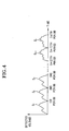
- the voltage values obtained from the cooking status detecting sensor 6 from the first turntable rotation period to the n th turntable rotation period are vary as defrosting progresses.
- S 1 , S 2 , S 3 , ... ,S n-1 , S n are the accumulations of the detected voltage values which are collected from the cooking status detecting sensor 6 during the power-on periods of respective turntable rotation periods.
- the accumulation of the detected voltage values of the respective turntable rotation periods will be called the "detected data”.
- the microcomputer 12 calculates the differences between the detected data (S 1 , S 2 , S 3 ,,,, S n ) for pairs of successive turntable rotation periods. The calculated differences are used as the compensating values for adjusting the next magnetron power-on period t on (n+1).
- the microcomputer 12 calculates the difference between the detected data (S 3 ) from the third turntable rotation period and the detected data (S 2 ) from the second turntable rotation period, and adjusts the magnetron power output requirement in accordance with the calculated difference.
- the adjusted magnetron output power requirement is used for adjusting the magnetron power-on period t on (n+1) in the fourth turntable rotation period.
- the microcomputer 12 calculates the difference between the detected data (S 1 ) and (S 2 ⁇ S n ) detected by the cooking status detecting sensor 6 during the first turntable rotation period and the second to the n th turntable rotation periods, respectively.
- the respective differences calculated between the detected data (S 1 ) and the respective detected data (S 2 ⁇ S n ) from the first turntable rotation period and the second to the n th turntable rotation periods are used as the compensating values for adjusting the magnetron power-on period t on (n+1) for the next respective turntable rotation periods.
- the food to be defrosted is placed in the cooking chamber of the microwave oven, and the cooking chamber door is closed. Then, the door position detection switching section 4 generates the door closed switching signal.
- the microcomputer 12 receives the door closed switching signal and sets the microwave oven on standby for defrosting operation (step ST10).
- step ST11 the microcomputer 12 determines whether then defrosting start key has been pressed.
- the microcomputer 12 drives the magnetron driving circuit 16 so that the magnetron 18 generates microwaves at a level appropriate for defrosting operation. Also, the microcomputer 12 drives the motor driving section 20 so that the turntable motor 22 is rotated to rotate the turntable 24 at a predetermined speed (step ST12).
- the microcomputer 12 regularly receives the voltage signals from the cooking status detecting sensor 6 when the turntable 24 is at the aforementioned positions P 1 , P 2 , P 3 , P 4 , ..., P n-3 , P n-2 , P n-1 , P n and thus collects the data (step ST13).
- the microcomputer 12 determines whether one turntable rotation period is completed at step ST14. If the microcomputer 12 determines that a turntable rotation period has been completed, the microcomputer 12 switches off the magnetron 18 (step ST15). Next, the microcomputer 12 accumulates the data collected from the cooking status detecting sensor 6 during the magnetron power-on period and calculates the difference between it an the previous value (step ST16). That is, as shown in Figure 5A, the microcomputer 12 calculates the absolute difference (
- the microcomputer 12 may calculate the absolute differences between the detected data (S 1 ) for the first turntable rotation period and the detected data (S 2 ⁇ S n ) for the present turntable rotation period. The calculated difference is used as a compensating value for adjusting the magnetron output power for the next turntable rotation period. After that, the microcomputer 12 determines whether the defrosting has been completed based on the calculation of the collected data (step ST17).
- the microcomputer 12 adjusts the magnetron power-on period by applying the compensating value from step ST18, and repeats steps ST12 to ST17.
- the magnetron power-on period is gradually reduced for successive turntable rotation periods and the magnetron power-off periods are gradually extended.
- the microcomputer 12 terminates the defrosting process (step ST19).
- the microcomputer 12 determines the slopes of the curves between the data points for successive turntable rotation periods. The slopes are compared with reference data regarding the magnetron output power adjustment range and the microcomputer 12 selects the most appropriate value in dependence on the slopes. The magnetron output power is adjusted according to the most appropriate value.
- a control program embodying a control algorthm for adjusting the magnetron output power as a function of the slopes, is stored in the memory 12A.
- a plurality of magnetron output power adjust ranges are stored in the memory 12A in table form.
- the slopes of the curves between successive data points obtained from the output of the cooking status detecting sensor 6 during successive turntable rotation periods is calculated.
- the calculated slope is compared with a plurality of reference values and the appropriate magnetron output power adjustment value is selected for use as the actual magnetron output power adjustment value.
- the slope of the curves between the data points for successive turntable rotation periods can be processed as a percentage in the above formula 6 and the percentage value can be used for determining the necessary change in the magnetron power-on period for the following turntable rotation period.
- the food to be defrosted is placed in the cooking chamber of the microwave oven, and the cooking chamber door is closed. Then, the door position detection switching section 4 generates the door closed switching signal.
- the microcomputer 12 receives the door closed switching signal and sets the microwave oven on standby for defrosting operation (step ST20).
- step ST21 the microcomputer 12 determines whether then defrosting start key has been pressed.
- the microcomputer 12 drives the magnetron driving circuit 16 so that the magnetron 18 generates microwaves at a level appropriate for defrosting operation. Also, the microcomputer 12 drives the motor driving section 20 so that the turntable motor 22 is rotated to rotate the turntable 24 at a predetermined speed (step ST22).
- the microcomputer 12 regularly receives the voltage signals from the cooking status detecting sensor 6 when the turntable 24 is at the aforementioned positions P 1 , P 2 , P 3 , P 4 , ..., P n-3 , P n-2 , P n-1 , P n and thus collects the data (step ST23).
- the microcomputer 12 determines whether one turntable rotation period is completed at step ST24. If the microcomputer 12 determines that a turntable rotation period has been completed, the microcomputer 12 switches off the magnetron 18 (step ST25). Next, the microcomputer 12 process the data collected from the cooking status detecting sensor 6 during the magnetron power-on period (step ST26). That is, the microcomputer 12 calculates the slope of the curve between the data points for the present and previous turntable rotation periods and selects the appropriate magnetron output power adjust value from the memory 12A.
- the microcomputer 12 determines whether or not the actual slope falls into the range between the minimum and maximum values S L and S H (step ST27). If it is determined that the actual slope falls outside the permitted range S L to S H , the microcomputer 12 substitutes the lowest and highest coefficients (K L and K H ) with another lowest and highest coefficients (K L and K H ) (step ST28), and obtains the minimum and maximum values S L and S H by another lowest and highest coefficients (K L and K H ) on the step ST26, and proceeds to the step ST27.
- the microcomputer 12 determines whether the data in the memory 12A includes a magnetron output power adjustment value for completing the defrosting operation (step ST29).
- the microcomputer 12 adjusts the magnetron power-on period in accordance with the adjustment percentage obtained from the lowest and highest coefficients (K L and K H ) of the magnetron output power adjustment range (step ST30), and proceeds to the step ST22.
- step ST31 If it is determined that the data does include data for completing defrosting operation, the microcomputer 12 completes the defrosting operation (step ST31).
- the microcomputer 12 After the turntable 24 is rotated for a certain period comprising a plurality of turntable rotation periods, the microcomputer 12 detects the change in the slope of the curve joining the data points for different turntable rotation periods. Then the microcomputer 12 obtains the defrosting completion time by determining whether the food in the microwave oven is a light load, a heavy load or no load, in accordance with the degree of the change in the slope of the detected data curve for the certain period.
- a control program implementing a control algorithm for determining completion of defrosting is stored in the memory 12A.
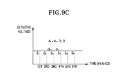
- the load status of the food is determined by multiplying the slopes (d n and d n-1 ) and drawing the following inferences: Formula 7 d n ⁇ d n - 1 ⁇ 0 ⁇ light load d n ⁇ d n - 1 > 0 ⁇ heavy load d n ⁇ d n - 1 ⁇ 0 ⁇ no load
- the product of the slopes will be less than "0", if one is positive and the other is negative.
- step ST40 the microwave oven is on standby for defrosting operation and the microcomputer 12 determines whether the defrosting start key has been pressed (step ST41).
- the microcomputer 12 Upon determining that the defrosting start key has been pressed, the microcomputer 12 controls the magnetron 18 to generate microwaves for defrosting. Also, the microcomputer 12 rotates the turntable 24 at a predetermined speed (step ST42).
- the microcomputer 12 regularly receives voltage signals from the voltage detecting section 8 reporting the standing wave magnitude (step ST43).
- the microcomputer 12 determines whether a turntable rotation period corresponding to three rotations of the turntable 24 has been completed at step ST44.
- step ST45 When the microcomputer 12 determines that a turntable rotation period has been completed, the microcomputer 12 switches off the magnetron 18 (step ST45).
- the microcomputer 12 processes the data collected from the cooking status detecting sensor 6 during the magnetron power-on period (step ST46), and adjusts the magnetron power-on and -off periods accordingly (step ST47).
- the microcomputer 12 determines whether the turntable 24 has been rotated for a predetermined time period, such as for two turntable rotation periods (step ST48).
- the microcomputer 12 When determining that a predetermined period is elapsed, the microcomputer 12 obtains the slopes (d n-1 , d n ) by calculating the differences between the first and second data points and the second and third data points for three successive turntable rotation periods. Then, the microcomputer 12 multiplies the slopes (d n ⁇ d n-1 ), to determine the load (step ST49). By the multiplication of the respective slopes (d n ⁇ d n-1 ), the microcomputer 12 determines whether the load of food is light or heavy or whether there is a no load condition (step ST50).
- step ST51 the microcomputer 12 proceeds to the step ST42 and drives the magnetron 18 in accordance with the magnetron power on/off periods adjusted in step ST47. If it is determined that there is a no load condition (step ST52), the microcomputer 12 stops driving the magnetron 18 to immediately terminate the defrosting operation (step ST53).
- step ST50 If the load is determined to be light at step ST50, the microcomputer 12 also terminates the defrosting operation (step ST53).
- the microcomputer 12 fits a cubic curve to the detected data, i.e. the accumulated total of the detected voltages from the respective turntable rotation periods. Then the microcomputer 12 differentiates the equation for cubic equation to obtain the maximum and minimum points of the cubic curve and adjusts the power of magnetron or determines the defrosting completion time from these values.
- a control program implementing a control algorithm for fitting a cubic curve to the data points, controlling the magnetron power and determining defrosting completion, is stored in the memory 12A.
- the microcomputer 12 calculates the time (t2-t1) between the maximum and the minimum (f(t1) and f(t2)) and the difference between the maximum and the minimum (f(t1)-f(t2)). The microcomputer 12 utilises these difference values for analysing the type and weight of the defrosting food.
- the difference value can be utilised as the compensating values for adjusting the magnetron power, or utilised as the values for a calculation for obtaining the defrosting completion time.
- the microcomputer 12 can utilise the roots when they are real or the same.
- the data points may all be the same as the completion of defrosting is approached and reached. Accordingly, considering such a defrosting characteristic, the microcomputer 12 obtains the difference between pairs of succeeding data points and adds differences obtained from at least five turntable rotation periods.
- the microcomputer 12 recognises that defrosting is completed and terminates the defrosting operation.
- step ST60 the microwave oven is on standby for defrosting operation and the microcomputer 12 determines whether the defrosting start key has been pressed (step ST61).
- the microcomputer 12 Upon determining that the defrosting start key has been pressed, the microcomputer 12 controls the magnetron 18 to generate microwaves for defrosting. Also, the microcomputer 12 rotates the turntable 24 at a predetermined speed (step ST62).
- the microcomputer 12 regularly receives voltage signals from the voltage detecting section 8 reporting the standing wave magnitude (step ST63).
- the microcomputer 12 determines whether a turntable rotation period corresponding to three rotations of the turntable 24 has been completed at step ST64.
- step ST65 When the microcomputer 12 determines that a turntable rotation period has been completed, the microcomputer 12 switches off the magnetron 18 (step ST65).
- the microcomputer determines whether the turntable 24 has rotated for five turntable rotation periods (step ST66)
- the microcomputer 12 calculates the differences (d n , d n-1 , d n-2 , d n-3 ) between the detected data for the respective turntable rotation periods, and accumulates the differences (d n , d n-1 , d n-2 , d n-3 ).
- the microcomputer 12 determines whether the accumulated total of the differences (d n , d n-1 , d n-2 , d n-3 ) is less than a predetermined value ( ⁇ ) (step ST67).
- the microcomputer 12 fits a cubic curve to the detected data for a plurality of turntable rotation periods (step ST68). Then, the microcomputer 12 calculates the maximum and minimum points (t1 and t2) by differentiation of the cubic equation (step ST69).
- the microcomputer 12 determines whether the roots, i.e., the points (t1 and t2), are imaginary (step ST70). If it is determined that the roots are imaginary, the microcomputer returns to the step ST62 to repeat the steps from ST62 to ST69.
- the microcomputer 12 adds one more turntable rotation period (step ST74), and returns to step ST67 to repeat the steps from step ST67 to step ST71.
- the microcomputer 12 recognises the type and weight of the defrosting food by the time and data variations ( ⁇ t and ⁇ f(t)), and adjusts the magnetron power according to the recognised status of the defrosting food (step ST75).
- step ST67 If the result of the step ST67 indicates that the accumulated total of the differences (d n , d n-1 , d n-2 , d n-3 ) is less than the predetermined value ( ⁇ ), the microcomputer 12 recognises that defrosting is complete and accordingly terminates the defrosting operation (step ST76).
- the microcomputer calculates the data of food in the microwave oven detected by a sensor, and accordingly adjusts the level of output power of magnetron and determines the defrosting completion time. Accordingly, regardless of various frozen status, weight, or size of the food, the user can perform the defrosting operation properly with one button manipulation for executing the defrosting operation of the microwave oven.
Landscapes
- Physics & Mathematics (AREA)
- Electromagnetism (AREA)
- Engineering & Computer Science (AREA)
- Chemical & Material Sciences (AREA)
- Combustion & Propulsion (AREA)
- Mechanical Engineering (AREA)
- General Engineering & Computer Science (AREA)
- Control Of High-Frequency Heating Circuits (AREA)
- Electric Ovens (AREA)
Description
- The present invention relates to a method of operating a microwave oven to defrost an item.
- Microwave ovens are well known and are used to cook food by irradiating it with microwaves. The microwaves cause water molecules in the food to vibrate thereby raising the temperature of the food.
- Microwave ovens are usually provided with a defrosting function for defrosting frozen food. When food is defrosted, the frozen food is placed in a cooking chamber of the microwave oven and weight of the food is input. Then a controller part of the microwave oven adjusts the output power of the oven's magnetron in dependence on the input weight.
- If a user inputs a desired defrosting time, the controller part of the microwave oven drives the magnetron for the input time with a corresponding magnetron power output level.
- However, there is a problem with the conventional defrosting function. More particularly, the user has to input the exact weight of the food to be defrosted. Consequently, food is sometime defrosted too little or too much since users do not always correctly enter the weight of the food.
- Furthermore, no account is taken of the degree to which the food is frozen.
- When the user inputs the defrosting time, the user usually sets the defrosting time by guesswork, preference, or based on past experience. Consequently, optimal defrosting is rarely achieved.
- Conventionally, defrosting is performed using a constant power level and is not controlled in dependence on the state of the food being defrosted during the defrosting process. This means that the user must open the oven's door to inspect the food to determine how the defrosting is progressing and adjust the defrosting time as the user deems necessary.
- A method according to the present invention is characterised by:-
- sensing a cooking parameter at predetermined intervals (e.g. using a standing wave sensor in a waveguide of the oven); and
- controlling the microwave energy applied to an item being defrosted in dependence on changes in said parameter.
- The microwave energy applied may be controlled in dependence on the change in said parameter across one interval. Alternatively, the microwave energy applied is controlled in dependence on the changes, if any, in said parameter over a plurality of intervals. In this case, the method preferably includes determining the time and value differences between a minimum and a maximum for said parameter, wherein the microwave energy applied is controlled in dependence on said differences, and/or determining the substantial absence of change in said parameter over a predetermined plurality of said intervals and terminating the application of microwave energy in response thereto.
- According to the present invention there is provided microwave oven configured to operate according to a method according to the present invention.
- Embodiments of the present invention will now be described, by way of example, with reference to the accompanying drawings, in which:-
- Figure 1 is a block diagram of a microwave oven employing a defrosting method according to the present invention;
- Figure 2 illustrates the turntable positions at which measurements are made for monitoring the defrosting process in a first method according to the present invention;
- Figure 3 illustrates how magnetron output power control effected in an embodiment of the present invention;
- Figure 4 is a plot illustrating the changing sensor signal obtained during defrosting;
- Figures 5A and 5B are plots illustrating an example in which the magnetron output power is adjusted in dependence on differences between data detected by the sensor;
- Figure 6 is a flowchart illustrating a first defrosting method according to the present invention;
- Figure 7 is a plot illustrating an example in which the slope of the curve between successive data points is determined as a percentage and used to control the magnetron output power;
- Figure 8 is a flowchart illustrating a second defrosting method according to the present invention;
- Figures 9A to 9C are plots illustrating an example in which the magnetron output power is adjusted in slopes of the sensor output with time;
- Figure 10 is a flowchart illustrating a third defrosting according to the present invention;
- Figures 11A and 11B are plots for illustrating an example in which the magnetron output power is adjusted by comparing maximum and minimum of the sensor output; and
- Figures 12A and 12B are flowcharts illustrating a fourth defrosting method according to the present invention.
- Referring to Figure 1, a microwave oven includes a
key input section 2, a door position detection switching section 4, a cooking status detection sensor 6, e.g. a standing wave sensor in the oven's waveguide, a voltage detecting section 8, astatus data memory 10, amicrocomputer 12 having amemory 12A, a highvoltage power circuit 14, amagnetron driving circuit 16, amagnetron 18, amotor driving section 20, aturntable motor 22, and aturntable 24. Thekey input section 2 includes a plurality of cooking item buttons for set various cooking conditions, a cooking start button and a defrosting start button. The door position detection switching section 4 detects whether the oven's cooking chamber door is open or closed and generates a corresponding door position signal. - The cooking status detecting sensor 6 employs an antenna disposed in a waveguide of the microwave oven for detecting the magnetic field of the standing wave in the waveguide formed by the superposition of the forward wave from the
magnetron 18 and the reflected wave from the defrosting food.. The antenna is as disclosed KR-A-98-161026 and KR-U-99-143508. - However, the cooking status detecting sensor 6 may include a plurality of sensors such as infrared sensors and temperature sensors for detecting the temperature of food, humidity sensors and gas sensors for detecting water vapour and gas from the food, light emitting and receiving elements for detecting the shape of the food, etc..
- The voltage detecting section 8 accurately detects voltage signals from the cooking status detecting sensor 6. If the cooking status detecting sensor 6 is an antenna, the voltage detecting section 8 includes a diode for rectifying the output voltage of the antenna, a smoothing capacitor for smoothing the rectified voltage and a resistor.
- The
status data memory 10 is used to store the defrosting status detecting data which is a result of regularly sampling the output of the cooking status detecting sensor 6 and values calculated therefrom. - Accordingly, after receiving the door closed signal from the door position detection switching section 4 and then after detecting operation of the defrosting start key, the
microcomputer 12 drives themagnetron 18 at a power level appropriate for the food being defrosted and rotates theturntable 24, which carries the food, a predetermined speed. - Hereinafter, one turntable rotation period means a predetermined number of turntable revolutions. During one turntable revolution period, the
microcomputer 12 receives data from the cooking status detecting sensor 6. Themicrocomputer 12 calculates the difference between the data for the present turntable rotation period and a previous one and adjusts the magnetron output power accordingly. - The
memory 12A stores a control program controlling themicrocomputer 12 for adjusting the magnetron power level for the defrosting function and for processing the defrosting status detect data obtained from the cooking status detecting sensor 6. - The
magnetron driving circuit 16 receives high-voltage power from the high-voltage power circuit 14 to drive themagnetron 18. - The
motor driving section 20 controlled by themicrocomputer 12 to drive theturntable motor 22 to rotate theturntable 24 at the predetermined speed. - Referring to Figure 2, during the rotation of the
turntable 24, themicrocomputer 12 collects the voltage signals which are output by the cooking status detecting sensor 6 when theturntable 24 is at a plurality of detecting positions (P1, P2, P3, P4, ..., Pn-3, Pn-2, Pn-1, Pn) on the regular basis when themagnetron 18 is on. Themicrocomputer 12 sets three rotations of the turntable 24 (T1, T2, T3; See Figure 3) as one turntable rotation period and cycles themagnetron 18 on and off once in each turntable rotation period, i.e., during every three revolutions of theturntable 24. One rotation of theturntable 24 takes 10 seconds, and accordingly, the speed of theturntable 24 is 6 rpm. - Referring to Figure 3, the
microcomputer 12 operates themagnetron 18 during a portion of the turntable rotation period, which comprises three revolutions T1, T2, T3 of theturntable 24. While themagnetron 18 is on, themicrocomputer 12 samples the voltage signals from the cooking status detecting sensor 6 at positions P1, P2, P3, P4, ..., Pn-3, Pn-2, Pn-1, Pn of theturntable 24. - The
microcomputer 12 calculates the difference between the data obtained from the present turntable rotation period and that from a previous turntable rotation period, and adjusts the magnetron power-on period for the next turntable rotation period in accordance with the calculated difference. - As shown in Figure 3, from the first turntable rotation period through the later turntable rotation periods, the magnetron power-on period is gradually shortened by a compensating value which is obtained from the difference between the data detected from the respective turntable rotation periods and the respective preceding turntable rotation periods. Accordingly, the magnetron power-on time PO is delayed as the magnetron power-on period is shortened. Also, as the power-on time PO is delayed, the power-off period is gradually increased so that the turntable rotation period remains constant.
- Thus, the magnetron power-on period (ton(n+ 1)) and the magnetron power-off period (toff(n+1)) are given by the following
formulas 1 and 2:
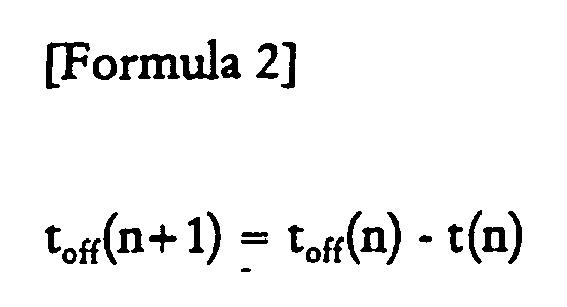
- According to the relation between the
formulas - Referring to Figure 4, the voltage values obtained from the cooking status detecting sensor 6 from the first turntable rotation period to the nth turntable rotation period are vary as defrosting progresses.
- Here, S1, S2, S3, ... ,Sn-1, Sn are the accumulations of the detected voltage values which are collected from the cooking status detecting sensor 6 during the power-on periods of respective turntable rotation periods. Hereinafter, the accumulation of the detected voltage values of the respective turntable rotation periods will be called the "detected data".
- In a first preferred embodiment of the present invention will now be described.
- Referring to Figure 5A, the
microcomputer 12 calculates the differences between the detected data (S1, S2, S3,,,, Sn) for pairs of successive turntable rotation periods. The calculated differences are used as the compensating values for adjusting the next magnetron power-on period ton(n+1). - According to Figure 5A for example, the
microcomputer 12 calculates the difference between the detected data (S3) from the third turntable rotation period and the detected data (S2) from the second turntable rotation period, and adjusts the magnetron power output requirement in accordance with the calculated difference. The adjusted magnetron output power requirement is used for adjusting the magnetron power-on period ton(n+1) in the fourth turntable rotation period. - The difference (dn) calculation between the respective data are obtained by the following absolute modulus:

- Referring to Figure 5B, in a variant of the first embodiment, the
microcomputer 12 calculates the difference between the detected data (S1) and (S2 ~Sn) detected by the cooking status detecting sensor 6 during the first turntable rotation period and the second to the nth turntable rotation periods, respectively. The respective differences calculated between the detected data (S1) and the respective detected data (S2 ~Sn) from the first turntable rotation period and the second to the nth turntable rotation periods are used as the compensating values for adjusting the magnetron power-on period ton(n+1) for the next respective turntable rotation periods. - Here, the differences (d1, d2, d3,..., dn) between the respective data are obtained by the following absolute values:


- The operation of a microwave oven according to the first preferred embodiment of the present invention will be described with reference to the flowchart of Figure 6.
- First, the food to be defrosted is placed in the cooking chamber of the microwave oven, and the cooking chamber door is closed. Then, the door position detection switching section 4 generates the door closed switching signal. The
microcomputer 12 receives the door closed switching signal and sets the microwave oven on standby for defrosting operation (step ST10). - Then the
microcomputer 12 determines whether then defrosting start key has been pressed (step ST11). - Upon determining that the defrosting start key has been pressed, the
microcomputer 12 drives themagnetron driving circuit 16 so that themagnetron 18 generates microwaves at a level appropriate for defrosting operation. Also, themicrocomputer 12 drives themotor driving section 20 so that theturntable motor 22 is rotated to rotate theturntable 24 at a predetermined speed (step ST12). - The
microcomputer 12 regularly receives the voltage signals from the cooking status detecting sensor 6 when theturntable 24 is at the aforementioned positions P1, P2, P3, P4, ..., Pn-3, Pn-2, Pn-1, Pn and thus collects the data (step ST13). - The
microcomputer 12 determines whether one turntable rotation period is completed at step ST14. If themicrocomputer 12 determines that a turntable rotation period has been completed, themicrocomputer 12 switches off the magnetron 18 (step ST15). Next, themicrocomputer 12 accumulates the data collected from the cooking status detecting sensor 6 during the magnetron power-on period and calculates the difference between it an the previous value (step ST16). That is, as shown in Figure 5A, themicrocomputer 12 calculates the absolute difference (|Sn-Sn-1|) between the detected data collected during the present turntable rotation period and during the previous turntable rotation period. Alternatively, as shown in Figure 5B, themicrocomputer 12 may calculate the absolute differences between the detected data (S1) for the first turntable rotation period and the detected data (S2 ~Sn) for the present turntable rotation period. The calculated difference is used as a compensating value for adjusting the magnetron output power for the next turntable rotation period. After that, themicrocomputer 12 determines whether the defrosting has been completed based on the calculation of the collected data (step ST17). - If it is determined that defrosting is not yet complete, the
microcomputer 12 adjusts the magnetron power-on period by applying the compensating value from step ST18, and repeats steps ST12 to ST17. - Accordingly, as shown in Figure 3, the magnetron power-on period is gradually reduced for successive turntable rotation periods and the magnetron power-off periods are gradually extended.
- If, however, it is determined that defrosting is complete, the
microcomputer 12 terminates the defrosting process (step ST19). - The operation of a microwave oven according to the second preferred embodiment of the present invention will now be described.
- First, since the construction of the microwave oven employing the defrosting method according to the second preferred embodiment is identical with the construction of the microwave oven according to the first preferred embodiment, the description thereof will be omitted.
- The
microcomputer 12 determines the slopes of the curves between the data points for successive turntable rotation periods. The slopes are compared with reference data regarding the magnetron output power adjustment range and themicrocomputer 12 selects the most appropriate value in dependence on the slopes. The magnetron output power is adjusted according to the most appropriate value. - A control program, embodying a control algorthm for adjusting the magnetron output power as a function of the slopes, is stored in the
memory 12A. A plurality of magnetron output power adjust ranges are stored in thememory 12A in table form. - Referring to Figure 7, the slopes of the curves between successive data points obtained from the output of the cooking status detecting sensor 6 during successive turntable rotation periods is calculated. In each case, the calculated slope is compared with a plurality of reference values and the appropriate magnetron output power adjustment value is selected for use as the actual magnetron output power adjustment value.
- The magnetron output power adjustment value for a slope (Sn-Sn-1) is obtained by the following formula 5:

where, SL and SH are the lowest and highest permitted values of the magnetron output power adjustment value. The lowest and highest values SL and SH are obtained by the following formula 6:-

- Referring to Figure 7, the slope of the curves between the data points for successive turntable rotation periods can be processed as a percentage in the above formula 6 and the percentage value can be used for determining the necessary change in the magnetron power-on period for the following turntable rotation period.
- The operation of the microwave oven according to the second preferred embodiment of the present invention will be described in greater detail below with reference to the flowchart of Figure 8.
- First, the food to be defrosted is placed in the cooking chamber of the microwave oven, and the cooking chamber door is closed. Then, the door position detection switching section 4 generates the door closed switching signal. The
microcomputer 12 receives the door closed switching signal and sets the microwave oven on standby for defrosting operation (step ST20). - Then the
microcomputer 12 determines whether then defrosting start key has been pressed (step ST21). - Upon determining that the defrosting start key has been pressed, the
microcomputer 12 drives themagnetron driving circuit 16 so that themagnetron 18 generates microwaves at a level appropriate for defrosting operation. Also, themicrocomputer 12 drives themotor driving section 20 so that theturntable motor 22 is rotated to rotate theturntable 24 at a predetermined speed (step ST22). - The
microcomputer 12 regularly receives the voltage signals from the cooking status detecting sensor 6 when theturntable 24 is at the aforementioned positions P1, P2, P3, P4, ..., Pn-3, Pn-2, Pn-1, Pn and thus collects the data (step ST23). - The
microcomputer 12 determines whether one turntable rotation period is completed at step ST24. If themicrocomputer 12 determines that a turntable rotation period has been completed, themicrocomputer 12 switches off the magnetron 18 (step ST25). Next, themicrocomputer 12 process the data collected from the cooking status detecting sensor 6 during the magnetron power-on period (step ST26). That is, themicrocomputer 12 calculates the slope of the curve between the data points for the present and previous turntable rotation periods and selects the appropriate magnetron output power adjust value from thememory 12A. - There are minimum and maximum slope values SL and SH determined by lowest and highest coefficients (KL and KH). The
microcomputer 12 determines whether or not the actual slope falls into the range between the minimum and maximum values SL and SH (step ST27). If it is determined that the actual slope falls outside the permitted range SL to SH, themicrocomputer 12 substitutes the lowest and highest coefficients (KL and KH) with another lowest and highest coefficients (KL and KH) (step ST28), and obtains the minimum and maximum values SL and SH by another lowest and highest coefficients (KL and KH) on the step ST26, and proceeds to the step ST27. - If it is determined that the slope falls within the allowable range between the minimum and maximum values SL and SH, the
microcomputer 12 determines whether the data in thememory 12A includes a magnetron output power adjustment value for completing the defrosting operation (step ST29). - If it is determined that data for completing defrosting operation is not present, the
microcomputer 12 adjusts the magnetron power-on period in accordance with the adjustment percentage obtained from the lowest and highest coefficients (KL and KH) of the magnetron output power adjustment range (step ST30), and proceeds to the step ST22. - If it is determined that the data does include data for completing defrosting operation, the
microcomputer 12 completes the defrosting operation (step ST31). - A third method according to the present invention will now be described in detail.
- After the
turntable 24 is rotated for a certain period comprising a plurality of turntable rotation periods, themicrocomputer 12 detects the change in the slope of the curve joining the data points for different turntable rotation periods.. Then themicrocomputer 12 obtains the defrosting completion time by determining whether the food in the microwave oven is a light load, a heavy load or no load, in accordance with the degree of the change in the slope of the detected data curve for the certain period. - A control program, implementing a control algorithm for determining completion of defrosting is stored in the
memory 12A. - Referring to Figures 9A to 9C, after obtaining both of the slope (dn-1) of the curve between the data point (S2 and S3) for the second and third rotation periods and the slope (dn) of the curve between the data points (S3 and S4) for the third and fourth rotation periods, the load status of the food is determined by multiplying the slopes (dn and dn-1) and drawing the following inferences:

- As shown in Figure 9A, in a first curve, the product of the slopes (d2, d3) of the curves between the second and third turntable rotation period data points (S2 and S3) and between the third and fourth turntable rotation period data points (S3 and S4) is less than "0". In the second curve, the product of the slopes (d3, d4) of the curves between the third and fourth turntable rotation period data points (S3 and S4) and between the fourth and fifth turntable rotation period data points (S4 and S5) is less than "0".
- The product of the slopes will be less than "0", if one is positive and the other is negative.
- As shown in Figure 9B, in the third or fourth curves, the slopes (dn and dn-1) are either always positive or negative. Consequently, the product of neighbouring slopes will always be positive.
- As shown in Figure 9C, the curve passing through the data points for the turntable rotation periods is substantially flat. Consequently, the products of neighbouring slopes will always be approximately "0".
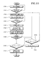
- A third method according to the present invention will now be described in detail with reference to the flowchart of Figure 10.
- Initially, the microwave oven is on standby for defrosting operation (step ST40) and the
microcomputer 12 determines whether the defrosting start key has been pressed (step ST41). - Upon determining that the defrosting start key has been pressed, the
microcomputer 12 controls themagnetron 18 to generate microwaves for defrosting. Also, themicrocomputer 12 rotates theturntable 24 at a predetermined speed (step ST42). - In this situation, the
microcomputer 12 regularly receives voltage signals from the voltage detecting section 8 reporting the standing wave magnitude (step ST43). - The
microcomputer 12 determines whether a turntable rotation period corresponding to three rotations of theturntable 24 has been completed at step ST44. - When the
microcomputer 12 determines that a turntable rotation period has been completed, themicrocomputer 12 switches off the magnetron 18 (step ST45). - Next, the
microcomputer 12 processes the data collected from the cooking status detecting sensor 6 during the magnetron power-on period (step ST46), and adjusts the magnetron power-on and -off periods accordingly (step ST47). - In this a situation, the
microcomputer 12 determines whether theturntable 24 has been rotated for a predetermined time period, such as for two turntable rotation periods (step ST48). - When determining that a predetermined period is elapsed, the
microcomputer 12 obtains the slopes (dn-1, dn) by calculating the differences between the first and second data points and the second and third data points for three successive turntable rotation periods. Then, themicrocomputer 12 multiplies the slopes (dn × dn-1), to determine the load (step ST49). By the multiplication of the respective slopes (dn × dn-1), themicrocomputer 12 determines whether the load of food is light or heavy or whether there is a no load condition (step ST50). - If it is determined that the load is heavy (step ST51), the
microcomputer 12 proceeds to the step ST42 and drives themagnetron 18 in accordance with the magnetron power on/off periods adjusted in step ST47. If it is determined that there is a no load condition (step ST52), themicrocomputer 12 stops driving themagnetron 18 to immediately terminate the defrosting operation (step ST53). - If the load is determined to be light at step ST50, the
microcomputer 12 also terminates the defrosting operation (step ST53). - A fourth preferred embodiment of the present invention will now be described.
- The
microcomputer 12 fits a cubic curve to the detected data, i.e. the accumulated total of the detected voltages from the respective turntable rotation periods. Then themicrocomputer 12 differentiates the equation for cubic equation to obtain the maximum and minimum points of the cubic curve and adjusts the power of magnetron or determines the defrosting completion time from these values. - A control program, implementing a control algorithm for fitting a cubic curve to the data points, controlling the magnetron power and determining defrosting completion, is stored in the
memory 12A. - Referring to Figure 11A, the
microcomputer 12 determines the cubic equation from the detected data (S1 ~Sn) collected for a plurality of the turntable rotation periods. Such is shown in the following formula 8:
- The cubic equation of formula 8 is differentiated and the points (t1 and t2) where slope of the cubic curve is "0" are obtained using formula 9:


- Accordingly, the
microcomputer 12 calculates the time (t2-t1) between the maximum and the minimum (f(t1) and f(t2)) and the difference between the maximum and the minimum (f(t1)-f(t2)). Themicrocomputer 12 utilises these difference values for analysing the type and weight of the defrosting food. - When the type and weight of the defrosting food are analysed, the difference value can be utilised as the compensating values for adjusting the magnetron power, or utilised as the values for a calculation for obtaining the defrosting completion time.
- However, whether to utilise the roots (t1 and t2) of f'(t) is determined by the following
formula 10 is a real or a multiple, or an imaginary root:
(f'(t) has two real roots if D > 0 , imaginary roots if D < 0 and both roots the same if D = 0. - Accordingly, the
microcomputer 12 can utilise the roots when they are real or the same. - Referring to Figure 11B, when defrosting certain foods, the data points may all be the same as the completion of defrosting is approached and reached. Accordingly, considering such a defrosting characteristic, the
microcomputer 12 obtains the difference between pairs of succeeding data points and adds differences obtained from at least five turntable rotation periods. Such is shown in the following formula 11: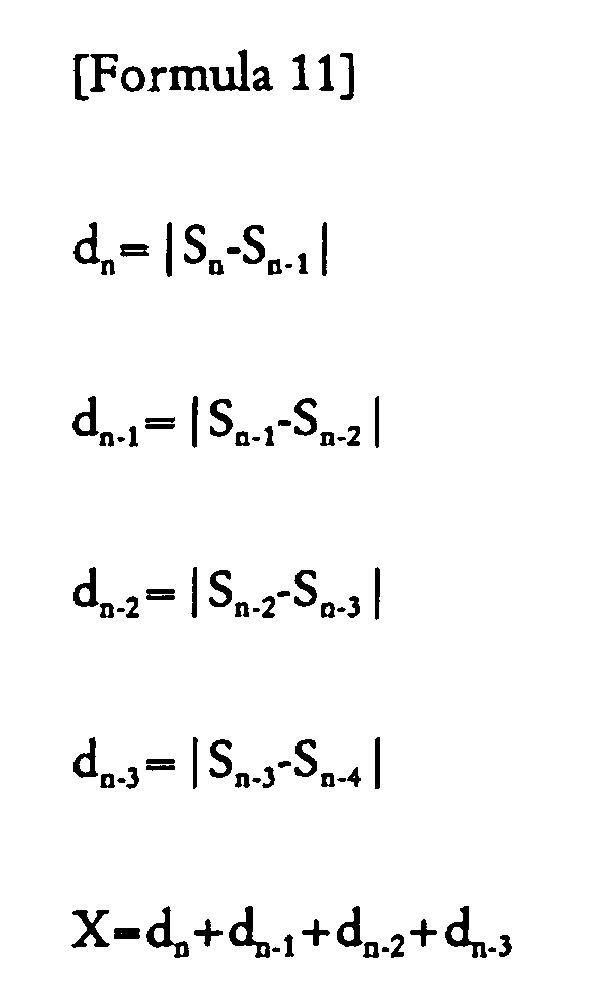
- Here, when the accumulated total (X) falls below a certain value, the
microcomputer 12 recognises that defrosting is completed and terminates the defrosting operation. - The fourth method according to the present invention will now be described in detail with reference to the flowchart of Figure 12.
- Initially, the microwave oven is on standby for defrosting operation (step ST60) and the
microcomputer 12 determines whether the defrosting start key has been pressed (step ST61). - Upon determining that the defrosting start key has been pressed, the
microcomputer 12 controls themagnetron 18 to generate microwaves for defrosting. Also, themicrocomputer 12 rotates theturntable 24 at a predetermined speed (step ST62). - In this situation, the
microcomputer 12 regularly receives voltage signals from the voltage detecting section 8 reporting the standing wave magnitude (step ST63). - The
microcomputer 12 determines whether a turntable rotation period corresponding to three rotations of theturntable 24 has been completed at step ST64. - When the
microcomputer 12 determines that a turntable rotation period has been completed, themicrocomputer 12 switches off the magnetron 18 (step ST65). - In this situation, the microcomputer determines whether the
turntable 24 has rotated for five turntable rotation periods (step ST66) - If it is determined that the
turntable 24 has been rotated for five turntable rotation periods, themicrocomputer 12 calculates the differences (dn, dn-1, dn-2, dn-3) between the detected data for the respective turntable rotation periods, and accumulates the differences (dn, dn-1, dn-2, dn-3). - The
microcomputer 12 determines whether the accumulated total of the differences (dn, dn-1, dn-2, dn-3) is less than a predetermined value (α) (step ST67). - If it is determined that the accumulated total is not less than the predetermined value (α), the
microcomputer 12 fits a cubic curve to the detected data for a plurality of turntable rotation periods (step ST68). Then, themicrocomputer 12 calculates the maximum and minimum points (t1 and t2) by differentiation of the cubic equation (step ST69). - The
microcomputer 12 determines whether the roots, i.e., the points (t1 and t2), are imaginary (step ST70). If it is determined that the roots are imaginary, the microcomputer returns to the step ST62 to repeat the steps from ST62 to ST69. - If it is determined that the roots are real, however, the
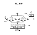
microcomputer 12 obtains the time difference (Δt) between them, and also obtains the data difference (Δf(t) = f(t1) - f(t2)) between them (step ST71). In this case, themicrocomputer 12 determines whether the time variation Δt) is greater than a predetermined time value (β) (step ST72) and determines whether the data variation (Δf(t)) is greater than a predetermined data value (γ) (step ST73). - According to the results of the steps ST72 and ST73, i.e. when the time variation (Δt) is greater than the predetermined time value (β), or when the data variation (Δf(t)) is less than the predetermined data value (γ), the
microcomputer 12 adds one more turntable rotation period (step ST74), and returns to step ST67 to repeat the steps from step ST67 to step ST71. - If it is determined that the time variation (Δt) is greater than the predetermined time value (β), or if the data variation (Δf(t)) is greater than the predetermined data value (γ), the
microcomputer 12 recognises the type and weight of the defrosting food by the time and data variations (Δt and Δf(t)), and adjusts the magnetron power according to the recognised status of the defrosting food (step ST75). - If the result of the step ST67 indicates that the accumulated total of the differences (dn, dn-1, dn-2, dn-3) is less than the predetermined value (α), the
microcomputer 12 recognises that defrosting is complete and accordingly terminates the defrosting operation (step ST76). - As described above, according to the present invention, during the defrosting operation of the microwave oven, the microcomputer calculates the data of food in the microwave oven detected by a sensor, and accordingly adjusts the level of output power of magnetron and determines the defrosting completion time. Accordingly, regardless of various frozen status, weight, or size of the food, the user can perform the defrosting operation properly with one button manipulation for executing the defrosting operation of the microwave oven.
Claims (20)
- A method of operating a microwave oven to defrost an item, the microwave oven having a magnetron (18) and a sensor (6) for sensing a cooking parameter, the method comprising the steps of:(a) operating the magnetron for an operational period within each of a first and second predetermined period;(b) detecting output data from the sensor for each of the predetermined periods;(c) calculating a difference between output data obtained from the first and second predetermined periods thereby obtaining a degree of change of the output data; and(d) adjusting a level of output power of the magnetron in accordance with the degree of change of the output data by adjusting the operation period of the magnetron.
- A method according to claim 1, wherein the level of output power of the magnetron is adjusted by shortening the operational period of the magnetron in a subsequent predetermined period.
- A method according to claim 1 or 2, wherein magnetron is switched on at a time (PO) in a predetermined time period, and the level of output power of the magnetron is adjusted by delaying the power-on time in a subsequent predetermined periods with respect to the power-on time in a preceding predetermined period.
- A method according to any preceding claim, wherein the first and second predetermined periods are equal to one another, and the level of output power of the magnetron is adjusted by increasing a power-off period of the magnetron in a subsequent predetermined period with respect two the preceding power-off period in the preceding predetermined period.
- A method as claimed in claim 1, wherein the step (d) further comprising adjusting the output power of the magnetron in accordance with an absolute value of the degree of change of the output data from the sensor.
- A method as claimed in claim 1, wherein the step (d) further comprises calculating a ratio of the output data with respect to an initial output data and adjusting the level of output power of the magnetron in accordance with the calculated ratio.
- A method as claimed in claim 1, wherein the step (d) further comprises calculating a magnetron output power adjust range including the degree of change of the output data from the sensor therein, and adjusting the level of the power of the magnetron in accordance with the calculated magnetron output power adjust range.
- A method as claimed in any one of claims 1, and 5 to 7, wherein the period over which the output data is detected by the sensor is measured in terms of a certain number of rotations of a turntable of the microwave oven on which the item to be defrosted is placed.
- A method as claimed in any one of the preceding claims, wherein the sensor comprises an antenna sensor for detecting magnetic field voltage of stationary waves of microwaves generated by the magnetron.
- A method as claimed in claim 9, wherein the antenna sensor keeps detecting the magnetic field voltage from a magnetron power-on time until a magnetron power-off time.
- A method as claimed in any one of the preceding claims, wherein the level of the output power of the magnetron is adjusted by controlling the operation period of the magnetron by adding and subtracting magnetron power on/off periods.
- A method as claimed in claim 5, further comprising the steps of:calculating a slope of the output data detected for the predetermined time period to provide a slope value; anddetermining a magnetron driving completion time by comparing the calculated slope value with a reference slope value.
- A method as claimed in claim 12, wherein the step of determining the magnetron driving completion time comprises multiplying a plurality of slope values varying for the predetermined time period.
- A method as claimed in claim 13, wherein the driving of magnetron is completed when a multiplication of the plurality of slope values is below a value of zero.
- A method as claimed in claim 13 or 14, wherein the driving of the magnetron is continued by adjusting the level of output power of the magnetron when a multiplication of the plurality of slope values is above a value of zero.
- A method as claimed in claim 13, wherein the driving of the magnetron is completed when a multiplication of the plurality of slope values equals a value of zero.
- A method according to any one of the preceding claims, further comprising the step of determining a defrosting completion time in accordance with the degree of change of the output data.
- A method as claimed in claim 17, wherein the step of determining a defrosting completion time determines the magnetron driving completion time in accordance with a summation of the degree of change of the data detected for the predetermined time period.
- A method as claimed in claim 17, wherein the step of determining a defrosting completion time calculates points for a local minimum and a local maximum of the detected data outputted for a predetermined time period and the local minimum and the local maximum, and adjusts the magnetron power according to the difference between the points and the difference between the local minimum and maximum.
- A microwave oven for defrosting an item, the microwave oven having a magnetron (18) and a sensor (6) for sensing a cooking parameter, the oven comprising:means configured for detecting a degree of change of output data from the sensor for a predetermined time period; andmeans for adjusting a level of output power of the magnetron in accordance with The degree of change of the output data by adjusting the operation period of the magnetron, wherein the adjusting means is operative in the event that the output data has changed over the period.
Applications Claiming Priority (4)
| Application Number | Priority Date | Filing Date | Title |
|---|---|---|---|
| KR9900762 | 1999-01-14 | ||
| KR19990000762 | 1999-01-14 | ||
| KR19990027331 | 1999-07-07 | ||
| KR9927331 | 1999-07-07 |
Publications (3)
| Publication Number | Publication Date |
|---|---|
| EP1021068A2 EP1021068A2 (en) | 2000-07-19 |
| EP1021068A3 EP1021068A3 (en) | 2003-09-17 |
| EP1021068B1 true EP1021068B1 (en) | 2007-03-21 |
Family
ID=26634582
Family Applications (1)
| Application Number | Title | Priority Date | Filing Date |
|---|---|---|---|
| EP00300261A Expired - Lifetime EP1021068B1 (en) | 1999-01-14 | 2000-01-14 | Microwave defrosting method |
Country Status (7)
| Country | Link |
|---|---|
| US (1) | US6166363A (en) |
| EP (1) | EP1021068B1 (en) |
| JP (1) | JP3795286B2 (en) |
| KR (1) | KR100341327B1 (en) |
| CN (1) | CN1253676C (en) |
| CA (1) | CA2295413C (en) |
| DE (1) | DE60033980T2 (en) |
Cited By (1)
| Publication number | Priority date | Publication date | Assignee | Title |
|---|---|---|---|---|
| EP2061287A2 (en) | 2007-11-15 | 2009-05-20 | Topinox Sarl | Method to stop the timing of a pulsed microwave generator for a cooking device and cooking device for this |
Families Citing this family (11)
| Publication number | Priority date | Publication date | Assignee | Title |
|---|---|---|---|---|
| KR100586510B1 (en) * | 2000-12-06 | 2006-06-07 | 삼성전자주식회사 | Microwave oven And Control Method thereof |
| US7199341B2 (en) * | 2002-08-02 | 2007-04-03 | Sharp Kabushiki Kaisha | High-frequency heating apparatus |
| DE102004015993B4 (en) * | 2004-04-01 | 2010-04-15 | Electrolux Schwanden Ag | Microwave oven and method of operating a microwave oven |
| US8653482B2 (en) * | 2006-02-21 | 2014-02-18 | Goji Limited | RF controlled freezing |
| KR101588830B1 (en) * | 2009-06-19 | 2016-01-26 | 엘지전자 주식회사 | A cooking apparatus using microwave |
| RU2012104702A (en) * | 2009-07-10 | 2013-08-20 | Панасоник Корпорэйшн | DEVICE FOR MICROWAVE HEATING AND METHOD FOR CONTROLLING MICROWAVE HEATING |
| EP3435736B1 (en) * | 2016-03-25 | 2021-07-28 | Panasonic Intellectual Property Management Co., Ltd. | Microwave heating apparatus |
| CN108679663A (en) * | 2018-05-21 | 2018-10-19 | 广东美的厨房电器制造有限公司 | Microwave oven defrosting control method, micro-wave oven, terminal and computer storage media |
| US10477585B1 (en) * | 2018-07-30 | 2019-11-12 | Amazon Technologies, Inc. | Microwave interference mitigation |
| CN110933795B (en) * | 2019-11-15 | 2022-02-25 | 广东美的厨房电器制造有限公司 | Microwave oven, control method and device thereof and storage medium |
| US20220015200A1 (en) * | 2020-07-13 | 2022-01-13 | Haier Us Appliance Solutions, Inc. | Cooking appliance with variable microwave and turntable timing |
Family Cites Families (12)
| Publication number | Priority date | Publication date | Assignee | Title |
|---|---|---|---|---|
| US4281022A (en) * | 1977-08-30 | 1981-07-28 | Litton Systems, Inc. | Method of cooking thin meats in a microwave oven |
| US4210795A (en) * | 1978-11-30 | 1980-07-01 | Litton Systems, Inc. | System and method for regulating power output in a microwave oven |
| US4317977A (en) * | 1979-09-06 | 1982-03-02 | Litton Systems, Inc. | Power controlled microwave oven |
| GB2117925B (en) * | 1982-02-19 | 1986-02-05 | Hitachi Heating Appl | Heating apparatus of thawing sensor controlled type |
| US4507530A (en) * | 1983-08-15 | 1985-03-26 | General Electric Company | Automatic defrost sensing arrangement for microwave oven |
| US4864088A (en) * | 1987-07-03 | 1989-09-05 | Sanyo Electric Co., Ltd. | Electronically controlled cooking apparatus for controlling heating of food using a humidity sensor |
| DE3743921A1 (en) * | 1987-12-23 | 1989-07-13 | Bosch Siemens Hausgeraete | CONTROL ARRANGEMENT FOR HEATING TECHNICAL TREATMENT OF FOODS BY MICROWAVE ENERGY |
| JPH0395314A (en) * | 1989-09-07 | 1991-04-19 | Matsushita Electric Ind Co Ltd | High frequency heating device |
| JPH03219587A (en) * | 1990-01-25 | 1991-09-26 | Matsushita Electric Ind Co Ltd | High frequency heating device |
| US5436433A (en) * | 1993-03-19 | 1995-07-25 | Goldstar Co., Ltd. | Automatic thawing device of microwave oven and control method thereof |
| KR960008974B1 (en) * | 1993-12-30 | 1996-07-10 | Lg Electronics Inc | Auto defrosting apparatus for microwave oven |
| KR100196692B1 (en) * | 1996-03-26 | 1999-06-15 | 구자홍 | Cover and volume detecting apparatus |
-
2000
- 2000-01-12 US US09/481,518 patent/US6166363A/en not_active Expired - Lifetime
- 2000-01-13 CA CA002295413A patent/CA2295413C/en not_active Expired - Fee Related
- 2000-01-14 EP EP00300261A patent/EP1021068B1/en not_active Expired - Lifetime
- 2000-01-14 KR KR1020000001670A patent/KR100341327B1/en not_active IP Right Cessation
- 2000-01-14 DE DE60033980T patent/DE60033980T2/en not_active Expired - Lifetime
- 2000-01-14 CN CNB001002937A patent/CN1253676C/en not_active Expired - Fee Related
- 2000-01-14 JP JP2000007167A patent/JP3795286B2/en not_active Expired - Fee Related
Cited By (1)
| Publication number | Priority date | Publication date | Assignee | Title |
|---|---|---|---|---|
| EP2061287A2 (en) | 2007-11-15 | 2009-05-20 | Topinox Sarl | Method to stop the timing of a pulsed microwave generator for a cooking device and cooking device for this |
Also Published As
| Publication number | Publication date |
|---|---|
| DE60033980T2 (en) | 2007-08-30 |
| KR20000053491A (en) | 2000-08-25 |
| CN1253676C (en) | 2006-04-26 |
| DE60033980D1 (en) | 2007-05-03 |
| KR100341327B1 (en) | 2002-06-22 |
| CA2295413A1 (en) | 2000-07-14 |
| CA2295413C (en) | 2003-04-15 |
| JP2000220838A (en) | 2000-08-08 |
| EP1021068A2 (en) | 2000-07-19 |
| CN1261144A (en) | 2000-07-26 |
| EP1021068A3 (en) | 2003-09-17 |
| JP3795286B2 (en) | 2006-07-12 |
| US6166363A (en) | 2000-12-26 |
Similar Documents
| Publication | Publication Date | Title |
|---|---|---|
| EP1021068B1 (en) | Microwave defrosting method | |
| EP1021067B1 (en) | Microwave oven operating method | |
| KR100411683B1 (en) | Heating cooker | |
| EP0268329B1 (en) | Microwave oven | |
| US4568201A (en) | Temperature measuring apparatus | |
| CA1199076A (en) | Microwave heating appliance with simplified user's operation | |
| CA1192618A (en) | Microwave oven with automatic cooking performance having additional heating process | |
| US6166362A (en) | Automatic cooking control method for a microwave oven | |
| US5545881A (en) | Heating time control apparatus and method thereof for microwave oven | |
| KR100186390B1 (en) | Method of defrosting frozen food in a microwave oven | |
| JP2856679B2 (en) | How to defrost food and drink in the microwave | |
| US5422465A (en) | Apparatus for and method of automatically heating foods in microwave oven | |
| EP0763963B1 (en) | Method for controlling cooking by using a vapor sensor in a microwave oven | |
| KR100214598B1 (en) | Microwave oven with temperature sensor | |
| AU771090B2 (en) | Defrosting method for a microwave oven | |
| US5698126A (en) | Microwave oven with food wrap film detecting function | |
| US6791070B2 (en) | Simmering control method in microwave oven | |
| JP3525254B2 (en) | High frequency heating equipment | |
| KR100341331B1 (en) | Defrosting Control Method For a Microwave Oven | |
| AU763026B2 (en) | Data obtaining method for a microwave oven | |
| AU1007900A (en) | Defrosting method for a microwave oven | |
| KR100191505B1 (en) | Weight value method | |
| KR0133437B1 (en) | Heating time controll method of microwave oven | |
| KR100354071B1 (en) | Method For Controlling Liquid Food Boiling Of a Microwave Oven | |
| JP2534763B2 (en) | microwave |
Legal Events
| Date | Code | Title | Description |
|---|---|---|---|
| PUAI | Public reference made under article 153(3) epc to a published international application that has entered the european phase |
Free format text: ORIGINAL CODE: 0009012 |
|
| AK | Designated contracting states |
Kind code of ref document: A2 Designated state(s): AT BE CH CY DE DK ES FI FR GB GR IE IT LI LU MC NL PT SE |
|
| AX | Request for extension of the european patent |
Free format text: AL;LT;LV;MK;RO;SI |
|
| RIN1 | Information on inventor provided before grant (corrected) |
Inventor name: LEE, WON-WOO Inventor name: SHON, JONG-CHULL Inventor name: LIM, DONG-BIN Inventor name: JANG, BO-IN |
|
| PUAL | Search report despatched |
Free format text: ORIGINAL CODE: 0009013 |
|
| AK | Designated contracting states |
Kind code of ref document: A3 Designated state(s): AT BE CH CY DE DK ES FI FR GB GR IE IT LI LU MC NL PT SE |
|
| AX | Request for extension of the european patent |
Extension state: AL LT LV MK RO SI |
|
| 17P | Request for examination filed |
Effective date: 20031103 |
|
| AKX | Designation fees paid |
Designated state(s): DE FR GB NL |
|
| RAP1 | Party data changed (applicant data changed or rights of an application transferred) |
Owner name: SAMSUNG ELECTRONICS CO., LTD. |
|
| GRAP | Despatch of communication of intention to grant a patent |
Free format text: ORIGINAL CODE: EPIDOSNIGR1 |
|
| GRAS | Grant fee paid |
Free format text: ORIGINAL CODE: EPIDOSNIGR3 |
|
| GRAA | (expected) grant |
Free format text: ORIGINAL CODE: 0009210 |
|
| AK | Designated contracting states |
Kind code of ref document: B1 Designated state(s): DE FR GB NL |
|
| REG | Reference to a national code |
Ref country code: GB Ref legal event code: FG4D |
|
| REF | Corresponds to: |
Ref document number: 60033980 Country of ref document: DE Date of ref document: 20070503 Kind code of ref document: P |
|
| ET | Fr: translation filed | ||
| PLBE | No opposition filed within time limit |
Free format text: ORIGINAL CODE: 0009261 |
|
| STAA | Information on the status of an ep patent application or granted ep patent |
Free format text: STATUS: NO OPPOSITION FILED WITHIN TIME LIMIT |
|
| 26N | No opposition filed |
Effective date: 20071227 |
|
| NLV4 | Nl: lapsed or anulled due to non-payment of the annual fee |
Effective date: 20080801 |
|
| PG25 | Lapsed in a contracting state [announced via postgrant information from national office to epo] |
Ref country code: NL Free format text: LAPSE BECAUSE OF NON-PAYMENT OF DUE FEES Effective date: 20080801 |
|
| PGFP | Annual fee paid to national office [announced via postgrant information from national office to epo] |
Ref country code: DE Payment date: 20140113 Year of fee payment: 15 |
|
| PGFP | Annual fee paid to national office [announced via postgrant information from national office to epo] |
Ref country code: FR Payment date: 20140113 Year of fee payment: 15 |
|
| PGFP | Annual fee paid to national office [announced via postgrant information from national office to epo] |
Ref country code: GB Payment date: 20140117 Year of fee payment: 15 |
|
| REG | Reference to a national code |
Ref country code: DE Ref legal event code: R119 Ref document number: 60033980 Country of ref document: DE |
|
| GBPC | Gb: european patent ceased through non-payment of renewal fee |
Effective date: 20150114 |
|
| PG25 | Lapsed in a contracting state [announced via postgrant information from national office to epo] |
Ref country code: GB Free format text: LAPSE BECAUSE OF NON-PAYMENT OF DUE FEES Effective date: 20150114 Ref country code: DE Free format text: LAPSE BECAUSE OF NON-PAYMENT OF DUE FEES Effective date: 20150801 |
|
| REG | Reference to a national code |
Ref country code: FR Ref legal event code: ST Effective date: 20150930 |
|
| PG25 | Lapsed in a contracting state [announced via postgrant information from national office to epo] |
Ref country code: FR Free format text: LAPSE BECAUSE OF NON-PAYMENT OF DUE FEES Effective date: 20150202 |