EP1021003B1 - Wireless Network - Google Patents
Wireless Network Download PDFInfo
- Publication number
- EP1021003B1 EP1021003B1 EP00200074A EP00200074A EP1021003B1 EP 1021003 B1 EP1021003 B1 EP 1021003B1 EP 00200074 A EP00200074 A EP 00200074A EP 00200074 A EP00200074 A EP 00200074A EP 1021003 B1 EP1021003 B1 EP 1021003B1
- Authority
- EP
- European Patent Office
- Prior art keywords
- channel
- base station
- terminal
- terminals
- signaling
- Prior art date
- Legal status (The legal status is an assumption and is not a legal conclusion. Google has not performed a legal analysis and makes no representation as to the accuracy of the status listed.)
- Expired - Lifetime
Links
Images


Classifications
-
- H—ELECTRICITY
- H04—ELECTRIC COMMUNICATION TECHNIQUE
- H04B—TRANSMISSION
- H04B7/00—Radio transmission systems, i.e. using radiation field
- H04B7/24—Radio transmission systems, i.e. using radiation field for communication between two or more posts
- H04B7/26—Radio transmission systems, i.e. using radiation field for communication between two or more posts at least one of which is mobile
- H04B7/2628—Radio transmission systems, i.e. using radiation field for communication between two or more posts at least one of which is mobile using code-division multiple access [CDMA] or spread spectrum multiple access [SSMA]
-
- H—ELECTRICITY
- H04—ELECTRIC COMMUNICATION TECHNIQUE
- H04B—TRANSMISSION
- H04B1/00—Details of transmission systems, not covered by a single one of groups H04B3/00 - H04B13/00; Details of transmission systems not characterised by the medium used for transmission
- H04B1/69—Spread spectrum techniques
- H04B1/707—Spread spectrum techniques using direct sequence modulation
- H04B1/709—Correlator structure
- H04B1/7093—Matched filter type
-
- H—ELECTRICITY
- H04—ELECTRIC COMMUNICATION TECHNIQUE
- H04B—TRANSMISSION
- H04B2201/00—Indexing scheme relating to details of transmission systems not covered by a single group of H04B3/00 - H04B13/00
- H04B2201/69—Orthogonal indexing scheme relating to spread spectrum techniques in general
- H04B2201/707—Orthogonal indexing scheme relating to spread spectrum techniques in general relating to direct sequence modulation
- H04B2201/70701—Orthogonal indexing scheme relating to spread spectrum techniques in general relating to direct sequence modulation featuring pilot assisted reception
-
- H—ELECTRICITY
- H04—ELECTRIC COMMUNICATION TECHNIQUE
- H04J—MULTIPLEX COMMUNICATION
- H04J13/00—Code division multiplex systems
- H04J13/0007—Code type
- H04J13/0022—PN, e.g. Kronecker
- H04J13/0029—Gold
-
- H—ELECTRICITY
- H04—ELECTRIC COMMUNICATION TECHNIQUE
- H04W—WIRELESS COMMUNICATION NETWORKS
- H04W72/00—Local resource management
- H04W72/20—Control channels or signalling for resource management
- H04W72/21—Control channels or signalling for resource management in the uplink direction of a wireless link, i.e. towards the network
Definitions
- the invention relates to a wireless network with at least one base station and a plurality of associated terminals for exchanging user and control data.
- the radio network consists of nichreren radio cells, each with a base station and located therein terminals or mobile stations. For example, after registering and synchronizing a terminal, upon request of a payload channel, a terminal sends a random access burst message over a Random Access Channel (RACH).
- RACH Random Access Channel
- the message packet consists of a preamble part and a data part.
- the preamble part consists of 16 orthogonal symbols (preamble sequence), which is spread by a gold code (preamble code / preamble code).
- the gold code contains 256 chip intervals.
- the data part contains a field with an identifier for the terminal, a field for identifying the requested service (short packet transmission, dedicated-channel set-up connection request, etc.), an optional field for data packets ( Optional user packet) and a CRC field for fault detection.
- a message packet received from a base station is supplied via a matched filter, a preamble correlator, a peak detector to a circuit portion estimating the timing of the data portion, which controls a RAKE circuit for evaluating the data portion.
- a correlation-based pulse detection with subsequent message decoding is used here.
- WO98 / 18289 describes a mobile radio system with a base station and a plurality of mobile stations, For channel capacity request, a mobile phone sends an Access Request Data Frame at the beginning of a random access frame. Before that, the mobile station is already synchronized with the base station. The mobile station determines the start time for each random access frame from a broadcast / pilot channel information broadcast by the base station. After the "Access Request Frame" is received and demodulated with a matched filter, the base station recognizes the request and controls the subsequent information transmissions of the mobile station. If channel capacities are available, the base station transmits a confirmation message to the mobile station. If no channel capacities are available, the base station transmits a "busy" message.
- a mobile station indicates a channel capacity request on the random access channel. To avoid collisions with simultaneous channel capacity requirements, repetitions of the random access signal from two mobile stations are stretched or the number of repetitions is reduced. These parameters, which indicate the number of repetitions and the intervals between repetitions, are broadcasted on the BCCH channel. Thus, the parameters are the same for all mobile stations.
- the invention has for its object to provide a wireless network in which a terminal exchanges signaling information with the associated base station in a different way.
- a wireless network having at least one base station and a plurality of associated terminals for exchanging payload and control data, in which the terminals for channel capacity request emit a signaling sequence, and the base station has a correlation device for correlation of a signal transmitted by one of the assigned terminals comprising the signaling sequence, wherein the correlation device is used for detecting a pulse resulting from the signaling sequence and the base station includes a channel access control provided after detection of the signaling sequence for rejecting or acknowledging the channel capacity requirement of the terminal for a shared channel of multiple terminals, wherein the base station includes means for providing to the associated terminals different start times within a reference frame for transmitting at least one signaling allocate for a channel capacity request.
- the wireless network is to be understood as meaning a network with a plurality of radio cells, in each of which one base station and a plurality of terminals transmit control and user data wirelessly.
- a wireless transmission is used to transmit information e.g. via radio, ultrasound or infrared paths.
- a terminal for transmitting user data must request a specific traffic channel at the assigned base station.
- a traffic channel may be, for example, a dedicated traffic channel (eg for voice transmission) either between the base station and the terminal or between two terminals.
- the assignment of the channels is carried out by the base station.
- a request, for example, for a dedicated traffic channel is transmitted from a terminal via a signaling channel predetermined by the base station. From the base station at least the start time of a possibly previously known signaling sequence must Terminals are communicated. It is also possible that apart from the start time, the terminals are also assigned one of several signaling sequences.
- a signaling sequence is a gold or Kasami sequence with good auto and cross-correlation properties.
- the base station contains a device (eg a matched filter) in which a correlation of the received signaling sequences is carried out.
- the resulting from the correlation pulse is detected and assigned to a terminal. Since a collision is avoided in the network according to the invention by different start times of the signaling sequences and no message decoding is performed according to a correlation-based pulse detection, but the appearance of the pulse resulting from the signaling sequence is regarded as a signaling request, signaling detection can be more robust and robust, especially at high traffic loads be performed faster than in the prior art.
- a specific time range for pulse detection is selected as a function of the start time of the signaling sequence and of the channel properties.
- Such a time range is referred to as a detection window.
- the length or duration and the start time of the detection window must be selected so that an impulse detection is possible.
- the detection windows are smaller than the time duration of the message packets known from the prior art. With the signaling according to the invention, therefore, many terminals within a short time range can issue a signaling request.
- a terminal in a radio cell always has the same starting time with respect to a reference frame after the registration and synchronization for the transmission of a signaling sequence, as long as the base station does not explicitly change this starting time.
- a signaling channel is initially permanently occupied for a terminal. Since many such start times may be included in the reference frame which is of short duration (eg 10 ms) and since all terminals of a radio cell use the same signaling sequence, only a small amount of network resources are consumed in the permanent assignment of a start time and a signaling sequence to a terminal ,
- the signaling sequences of all terminals in a radio cell have different start times. In the simplest case, the same signaling sequences are used by each terminal. The signaling sequences can therefore be partially overlaid, since the length of a sequence is usually longer than the distance of two consecutive start times.
- An advantage of the network according to the invention is also the security of the recognition of a signaling request.
- a detectable pulse is almost always generated after the transmission of a signaling sequence. This is because spurious signals and channel noise can lead to "artificial" pulses at the output of the matched filter. It is very unlikely that these will reduce the amplitude of the pulses at the output of the matched filter upon receipt of an actual transmitted signaling sequence. In the worst case (for example, in the case of disturbances), a false alarm is thus triggered if the amplitude of the noise or interference signal exceeds the detection threshold without a signaling sequence having been sent.
- the signaling sequence can also be used to request channel capacity of a shared channel (shared uplink channel).
- the base station upon receipt of a signaling sequence, either rejects a request or acknowledges the request of a terminal for channel capacity in a channel shared by multiple terminals. Using a shared channel results in a capacity increase due to static effects.
- the acknowledgment or rejection of a channel capacity for at least one terminal transmits the base station to the relevant terminal via an allocation control channel.
- the base station transmits further information concerning the transmission of the payload data over the shared channel. Such information may relate to the start time of the transmission of the user data, the data rate, the transmission power, the spreading factor, etc.
- the shared channel can be used eg by 8 terminals for the transmission of user data. If another terminal wants to use this channel, This terminal sends out another specific signaling sequence.
- the base station checks whether the terminal can be included in the group of the channel shared by several terminals. If the test result is positive, the base station notifies the relevant terminal that it will be included in the group.
- Fig. 1 is a wireless network, such as a wireless network, with multiple base stations 1 to 3 and multiple terminals 4 to 14 shown.
- a base station 1 to 3 are assigned to certain terminals 4 to 14.
- the base station 1 to 7 the base station 2, the terminals 8 to 10 and the base station 3, the terminals 11 to 14 assigned.
- a control data exchange takes place at least between the base station and the terminals.
- a user data exchange can be carried out both between the base station and the terminals and directly between the terminals. In both cases, the base station establishes the connection for transmitting user data.
- the terminals 4 to 14 are usually mobile stations, which are controlled by a fixed base station 1 to 3. If appropriate, a base station 1 to 3 can also be mobile or mobile.
- radio signals are transmitted by the FDMA, TDMA or CDMA (Frequency Division Multiplex Access) (TDMA) method or by a combination of the methods.
- FDMA Frequency Division Multiplex Access
- CDMA Frequency Division Multiplex Access
- a user-originated binary information is modulated with a different code sequence each time.
- a code sequence consists of a pseudo-random square-wave signal (pseudo noise code) whose rate, also called chip rate, is generally much higher than that of the binary information.
- the duration of a rectangular pulse of the pseudorandom square wave signal is referred to as the chip interval T C. 1 / T C is the chip rate.
- the base stations are assigned to certain radio cells in which the data traffic is handled with each located in the radio cell terminals. If a terminal moves from one radio cell to another radio cell, the assignment of the terminal from one to the other base station is handled according to certain specifications. At the same time, this terminal can exchange data with the base stations of the two radio cells during the transition from one radio cell to another. This is called soft handover.
- a radio cell is in Fig. 1 indicated by a dashed circle.
- User data and control data between at least one terminal and one base station are transmitted via channels predetermined by the base station.
- the radio connection from the base station to the terminals is referred to as downlink and from the terminals to the base station as uplink.
- data is transmitted via downlink channels from the base station to the terminals and over the uplink channels from terminals to the base station.
- a downlink control channel may be provided which is used to distribute control data from the base station to all terminals prior to establishing a connection.
- Such a channel is called a downlink distribution control channel.
- an uplink control channel assigned by the base station can be used, but to which other terminals can also access.
- An uplink channel that can be used by multiple or all terminals is referred to as a common uplink channel.
- payload data are transmitted via a downlink and an uplink traffic channel.
- channels called peer-to-peer payload channels are used.
- Channels that are established only between a transmitter and a receiver are referred to as dedicated channels.
- a traffic channel is a dedicated channel that can be accompanied by a dedicated control channel for transmission of connection-specific control data.
- a channel is characterized by a frequency range, a time range and e.g. determined by a spreading code in the CDMA method.
- the terminal For user data to be exchanged between the base station and a terminal, it is necessary for the terminal to be synchronized with the base station.
- GSM Global System for Mobile Communication
- the temporal position of a frame is determined on the basis of predefined parameters after the determination of a suitable frequency range ( Frame synchronization), with the aid of which the time sequence for the transmission of data takes place.
- a suitable frequency range Frame synchronization
- Such a framework is always necessary for the data synchronization of terminals and base station in TDMA, FDMA and CDMA methods.
- Such a frame may contain various subframes or subframes or form a superframe with several other consecutive frames. For reasons of simplification, the following is based on a frame which is referred to as a reference frame.
- the pulse duration is exactly the same as the time interval required to transmit one bit.
- the pulse duration corresponds to a chip interval.
- One bit interval corresponds to several chip intervals.
- the transmission of a special pulse sequence by the base station is required.
- the start time of the pulse sequence corresponds to the start time of a frame.
- a terminal eg one of the terminals 4 to 7 in Fig. 1
- this must be for transmission a traffic channel for a downlink and an uplink connection or a peer-to-peer traffic channel from the associated base station (eg base station 1 in Fig. 1 ) to provide.
- the base station eg the base station 1 in Fig. 1
- the associated terminals eg, terminals 4 to 7
- a downlink broadcast control channel during arbitrary frame control data.
- Such a signaling sequence transmitted by a terminal is a pseudo-random square-wave signal and indicates that this terminal requests a traffic channel.
- Each terminal is therefore assigned an uplink signaling channel for transmitting a signaling sequence from the base station, via which signaling sequences are transmitted.
- the base station can perform the allocation of the signaling sequence and the sequence start time for each terminal only once. This can happen, for example, during the registration of a terminal at the associated base station.
- the assignment of the sequence start times can also - as will be explained below - depending on the different channel characteristics of the connections between the base station and terminals done.
- a signaling channel is realized in the invention by the particular signaling sequence and its start time.
- All terminals assigned to a base station transmit the same signaling sequence but at different times (sequence start times). Consequently, different base stations assign different signaling sequences to their assigned or registered terminals. However, it is sufficient if only the neighboring base stations each have different signaling sequences. For example, if a terminal is registered with a transition from one radio cell to another at two base stations, it sends out the signaling sequence that the base station from which a traffic channel is requested.
- a base station includes a single matched filter and a downstream pulse detector for detecting the signaling sequences transmitted by the terminals.
- the matched filter is clocked at a clock rate that is at least equal to the maximum chip rate when using a code spread or equal to the maximum bit rate when no code spread is used. From the terminals such signaling sequences are sent out, which have a good autocorrelation property. This means that the pulses resulting from the successive signaling sequences of different terminals at the output of the matched filter can be unambiguously detected by the pulse detector within a detection window.
- the choice of clock rate as a function of the maximum chip rate and a signaling sequence with good autocorrelation properties allows the successive signaling sequences to have a minimum time interval between their start times.
- the signaling sequence should have a good cross-correlation property, ie the correlation to other signals transmitted in the network should be low.
- the other signals transmitted in the network and received by the matched filter are interpreted by the pulse detector as a negligible noise signal and, on the other hand, the signaling sequences of other circuit elements in the base station which process the other signals transmitted in the network are interpreted as negligible noise .
- Such a signaling sequence with good auto and cross-correlation properties is for example the one from the book " JG Proakis: Digital Communications by JG Proakis, Third Edition, McGraw-Hill International Editions, 1995, pages 724-729 "known sequence of gold and Kasami.
- the resulting at the output of the matched filter pulses are a measure of the energy of the signaling sequences.
- the sequence start time of a signaling sequence should be set by the base station so that the matched filter in the base station generates a pulse after the detection of a signaling sequence of a terminal assigned to it in a predetermined detection window.
- This detection window has the duration or length ⁇ .
- the signaling sequences can be sent out at any sequence start times.
- a sequence start time is associated with the occurrence of a pulse at the output of the matched filter.
- the detection begins after transmission of a signaling sequence and a delay caused by the channel characteristic of a connection between at least one terminal and a base station.
- the channel characteristic is the physical characteristic of a channel.
- a channel property results, for example, from the distance between the terminal and the base station. Consequently, it is possible for the pulse detector to use different width detection windows for the various terminals. For the sake of simplicity, a uniform width of the detection window is selected here.
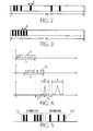
- the sequence of arbitrarily occurring detection windows of duration ⁇ is with respect to the reference frame of length FR in Fig. 2 shown.
- the matched filter usually generates from a received signaling sequence a pulse train having a main pulse and a plurality of secondary pulses often distributed symmetrically around the main pulse.
- the amplitude of the secondary pulses is regularly smaller than the amplitude of the main pulse.
- the various main pulses generated by the matched filter must have a guard time so that the channel-skewed pulse trains of the different terminals appearing at the output of the matched filter do not overlap so that unambiguous detection becomes impossible. With a certain overlap, the base station can not uniquely assign the pulses to a terminal.
- the width or duration ⁇ of the detection window must therefore be at least equal to the main pulse width, which results without channel influence, and an additional channel-dependent safety interval. This also results in the spacing of successive, identical signaling sequences.
- an optimized distance of the sequence start times can be provided according to the invention. This means that in each case the width of the detection window is determined as a function of the channel properties between a terminal and the base station. Another possibility according to the invention that is easier to implement is that the signaling sequences are transmitted successively at a constant distance. When determining the constant distance, the worst channel properties must be considered.
- Fig. 3 shows the continuously successive detection windows with respect to the reference frame of length FR, which result as a consequence of the signaling sequences transmitted at a predetermined constant distance.
- Fig. 4 Two exemplary signaling sequences S 1 and S 2 are shown, which have the sequence duration or sequence length L 1 and L 2 . After a delay time p 1 and p 2 caused by the channel properties, the detection process or the detection window of length ⁇ respectively starts. In such a detection window, a main pulse and secondary pulses assigned to a signaling sequence appear.
- the length ⁇ of the detection window is determined in particular by three factors (channel properties). First, the accuracy of estimating the propagation delay of the data to be transmitted from the terminals to the base station, secondly the delay spread characteristic due to multiple propagation and thirdly the autocorrelation properties of the signaling sequences terminals are considered.
- the terminals are usually at different distances from the base station. This leads to different propagation delays of the signaling sequences emitted by the terminals.
- the propagation delay between the terminal MT i and the base station B should be equal to p i and the length of the signaling sequence equal to L.
- the base station When the base station expects a pulse for the terminal MT i at the output of the matched filter at time t i , it instructs the terminal MT to begin transmitting the signaling sequence at time t 1 -p i -L.
- the pulse at the output of the matched filter is inaccurate. This inaccuracy in the estimation of the propagation delay p i must be compensated by a sufficiently long detection window ⁇ . If the maximum uncertainty in the estimate is j for all terminals, the detection window must be greater than j.
- the data between a terminal and a base station are usually transmitted not only over one radio path but over several (multiple propagation). Due to reflection and diffraction effects, the signal transmitted from a terminal to the base station passes through various paths and the resulting multi-path signals are received by the base station at different times. This results in the output of the matched filter for a signaling sequence not only a single main pulse, but appear at the output of the matched filter other main pulses. These further main impulses are produced at the output of the matched filter by signals which have arisen due to the multiple propagation and which are grouped around the actual main impulse. The actual main pulse is produced at the output of the matched filter from the received actual signaling sequence.
- the length ⁇ of the detection window must be greater than a window of length w, which contains the actual main pulse and the other main pulses. It should be noted that even without multiple propagation at the output of the matched filter not only an actual main pulse, but also secondary pulses appear. However, the amplitude of the sub-pulses is much smaller than the amplitude of the main pulse due to the good autocorrelation properties described above.
- the autocorrelation property of the signaling sequence is the measure of the width of the main pulse and the minima and maxima of the sub-pulses at the output of the matched filter (ignoring the channel characteristics).
- the main pulse at the output of the matched filter is approximately equal to the energy of the signaling sequence.
- the amplitude of the main pulse is much larger than that of the secondary pulses.
- the energy of the signaling sequence is thus determined by its amplitude and duration or length.
- the signaling sequence e.g., gold or Kasami sequence
- the signaling sequence should have a significantly lower amplitude than the other signals.
- the signaling sequence must be sufficiently long.
- the detection duration of a signaling sequence and thus the assignment of user channels of the base station to the terminal are extended.
- the length of a signaling sequence affects both the autocorrelation property of the signaling sequence and the signaling time. For a given signaling sequence, if the autocorrelation function is sufficiently large within a time interval q, ⁇ must be greater than q.
- the duration ⁇ of the detection window is dimensioned so that only a single signaling sequence can be detected.
- a base station receives binary information or 1-bit information.
- This binary information indicates whether a terminal which has transmitted the signaling sequence requests a new traffic channel (pulse at the output of the matched filter during the duration of the detection window) or no traffic channel (pulse at the output of the matched filter during the duration of the Detection window not available).
- the following is the extension of transmission from 1-bit to n-bit information (n> 1, n is an integer).
- a terminal sends the same signaling sequence not once but several times in succession per reference frame to provide the base station n-bit information available.
- n-bit information is achieved by extending the detection window by increasing the duration or length of the detection window for each affected terminal by a factor of n.
- n signaling sequences of a terminal can be detected during the occurrence of the n-times enlarged detection window.
- the terminal which transmits an n-bit information (signaling data), uses identical signaling sequences whose start times are shifted by the value ⁇ in each case.
- a transmitted signaling sequence then indicates, for example, a "1" and a non-transmitted signaling sequence a "0".
- FIG. 5 an example of the position of pulses detected from identical signaling sequences is shown.
- a first group G1 of pulses is signaling sequences of a first terminal and a second group G2 of pulses is associated with signaling sequences of a second terminal.
- the first group G 1 yields the 7-bit information "1100111" and the second group G2 the information "0100101".
- the information "001" may mean that the terminal requests an 8 kbit / s traffic channel.
- the information "001" is generated by two not emitted and one emitted signaling sequence.
- the desire for a 64 kbit / s traffic channel of a terminal may be expressed by the information "010" and the desire for a 144 kbit / s traffic channel of a terminal may be expressed by the information "011".
- the matched filter in the base station is hereby intended to receive both 1-bit and n-bit information, since in both cases the same signaling sequence is received. In the two cases, only the post-processing of the pulses detected by the matched filter differs. An information processing will in the first case after the duration ⁇ for the detection of a signaling sequence and in the second case after the duration n ⁇ for the detection of n signaling sequences.
- the number of signaling channels of a base station using a single signaling sequence is limited to the value FR / ⁇ , where FR is the length of the reference frame and ⁇ is the length of a detection window.
- FR is the length of the reference frame
- ⁇ is the length of a detection window.
- each detection window is the same length and has the length ⁇ .
- a base station wants to allocate more signaling channels than given by the value FR / ⁇ , it can assign to the terminals not only a single but different signaling sequences. For example, during a reference frame 100, identical signaling sequences can be detected by the matched filter. But are they e.g.
- 120 terminals in the radio cell that want to send a signaling sequence it is not possible that all these 120 terminals use the same signaling sequence. Therefore, e.g. 60 terminals transmit a first and the other 60 terminals a second signaling sequence, which can then be detected by two different matched filters in the base station. It should also be mentioned that the sequence start times of the different signaling sequences are independent of one another, that is, coordination with one another is not necessary. Only the start times of the same signaling sequences must be coordinated.
- UMTS Universal Mobile Telecommunication System
- a recipient Fig. 6
- a transmitter Fig. 7
- a receiver Fig. 8
- a transmitter Fig. 9
- FIG. 6 shown block diagram of a receiver of a base station contains as known Elements (eg from the GSM mobile radio system or a CDMA system) an antenna 15, a high-frequency block 16, an intermediate frequency block 17, an analog-to-digital converter 18, a demodulator 19 and a block 20, for example, the switching functions channel demultiplexing, deinterleaving, channel decoding and also performs despreading using a CDMA system.
- the baseband control and payload signals are applied to a channel access control block 23, which forwards the various signals to the appropriate units for further processing, such as a central office.
- a matched filter 21 is inserted into the receiver of the base station, which checks the received signals for the presence of a signaling sequence.
- a signaling sequence has been detected during the expected time period (detection window), ie at least one pulse is generated, this is detected by a subsequent pulse detector 22 and reported to the channel access control block 23, which may be a processor, for example.
- the channel access control block 23 forwards this message to downstream further control elements, not shown here, which then assign a user channel to the terminal, for example by means of generated control data via the transmitter of the base station.
- the duration or length ⁇ of the detection window may be fixed and determined for example by measurements before the normal operation of the network. It is also possible to determine the duration ⁇ of the detection window for each terminal individually during operation.
- the duration ⁇ of the detection window for a specific signaling sequence and of a terminal is supplied in this case by a control element, not shown here, to the pulse detector after the evaluation of measurement results.
- the distance between a base station and a terminal is evaluated on the basis of the signals received by the terminal in the base station.
- the information processing of the pulses generated by the matched filter 21 detected by the pulse detector 22 is performed in the channel access control block 23.
- a specific detection window is assigned to a terminal. If at least one main pulse is detected in such a detection window, the channel access control block 23 determines that there is a request from the terminal for a useful channel. From this request and inquiries of other terminals and considering the existing connections or the granting user channels, decides a control not shown in detail after receiving the request from the channel access control block 23, whether the requesting terminal, a traffic channel can be provided. If an allocation of a user channel is possible, this user channel is determined and after processing in the transmitter of the base station ( Fig. 7 ) is supplied to the terminal via a downlink distribution control channel.
- the base station transmitter also includes a channel access control block 24 which receives data from various sources 25.
- a source may be, for example, an exchange providing user data or a control element which supplies control data.
- these control data may contain information about a useful channel to be used for a terminal which has previously requested a user channel by means of a signaling sequence.
- the control block 24 subsequent block 26, for example, performs the switching functions channel coding, interleaving, channel multiplexing and when using a CDMA system also a spreading.
- the output of the block 26 is passed through a modulator 27, a digital-to-analog converter 28, an intermediate frequency block 29 and a high frequency block 30 to an antenna 31. All elements 25 to 31 may be elements known from existing mobile radio systems.
- FIG. 8 A block diagram of a receiver of a terminal is shown Fig. 8 ,
- This receiver contains, as elements known for example from the GSM mobile radio system or a CDMA system, an antenna 32, a radio frequency block 33, an intermediate frequency block 34, an A / D converter 35, a demodulator 36, a block 37 with different functions and a channel access control block 38, the control and user data to various sinks (eg, low frequency circuit for converting user data in voice data).
- the block 37 is responsible, for example, for the switching functions channel demultiplexing, deinterleaving, channel decoding and when using a CDMA system for despreading.
- the channel access control block 38 evaluates certain channels relevant to the terminal, such as a payload channel or a downlink distribution control channel.
- Circuit element passed in the terminal.
- the channel access block 38 extracts, for example, the information to which start time, at least one signaling sequence can be sent out. This information is passed to at least one circuit element not shown here.
- the terminal contains in its transmitter, its associated block diagram in Fig. 9 Also shown is a channel access control block 39 that controls a channel access.
- the channel access control block 39 provides a block 42 which performs, for example, the switching functions channel coding, interleaving, channel multiplexing and also spreading using a CDMA system.
- the channel access control block 39 indicates to a timer 40 the start timing of a signaling sequence.
- the payload and control data are obtained from the channel access control block 39 from various sources.
- a source may be, for example, a low-frequency circuit which supplies voice data as payload data, or a control element which supplies control data.
- this control data may be information about the start time of a signaling sequence.
- the timing controller 40 provides timestamps to a generator 41 to generate a signaling sequence.
- the time stamps may be, for example, the start and end times of rectangular pulses of the signaling sequence.
- the generator contains a memory for storing various signaling sequences.
- the signaling sequence to be transmitted is selected by the channel access control block. If appropriate, signaling sequences can be written into the memory of the generator 41.
- the generator 41 and the timing element 40 are initialized upon receipt of the information about the signaling sequence to be used and the start time of the signaling sequence. If no change in signaling sequence and / or start time is indicated by the associated base station, further initialization of generator 41 and timing element 40 is not required.
- the useful and control data processed in block 42 are supplied to a superposition circuit 43 which still receives the output signals of the generator 41.
- the output from the superposition circuit 43 output signal is transmitted via a modulator 44, a digital-to-analog converter 45, an intermediate frequency block 46 to a high-frequency block 47, by means of an antenna 48 in the High frequency block emitted signals.
- a signaling sequence transmitted by a terminal is used to request a traffic channel from the associated base station. This is usually a dedicated channel. This request occurs after a terminal has been synchronized with and registered with the base station.
- the signaling sequence may also be used to request a shared uplink channel for transmission of packets.
- a shared uplink traffic channel is a channel for simultaneously transmitting payload data from multiple terminals to the base station. For example, 8 terminals designated by the base station can simultaneously use this channel.
- a signaling sequence is sent from a terminal to a start time specified by the base station, this means requesting a certain capacity (e.g., 16 kbit / s) of the channel for transmission of payload data.
- the base station transmits a confirmation or rejection of the reservation of channel capacity via a special control channel called the Access Control Channel.
- the terminal With the confirmation of the capacity reservation, the terminal is still informed via the allocation control channel various information necessary for the transmission of the user data. If a CDMA method is used to transmit the payload data, the allocation control channel is used to transmit to the terminal the start time of the transmission of the payload data, the data rate, the transmission power and the spreading factor for the shared uplink traffic channel. After the terminal has received the information about the start time and the spreading factor, the terminal starts to transmit the user data packed in packets.
- the base station defines a certain number of terminals (eg 8) that can use the shared uplink traffic channel to transmit packetized payload data.
- a terminal that is not yet a user of this shared uplink traffic channel may look for a corresponding one Requirement as a new user of the channel from the base station will be determined.
- either another terminal, which is previously part of the group of terminals using the shared uplink traffic channel can be removed for the new terminal, or the new terminal can be added in addition to the group if the channel capacity still has free resources. Care must be taken to ensure that the interference generated within the system is not exceeded by the addition of the terminal. For example, if a terminal is to be removed, the terminal will be removed from the base station if that terminal has no longer requested any channel capacity for the shared uplink traffic channel (that is: transmission power for particular data rate, time slot, spreading factor, carrier frequency).
- a terminal wishing to become a user of the shared uplink payload channel sends a signaling sequence at a start time determined by the base station. This start time may be known to the terminals or is communicated from the base station to the terminal each after it has been sent via a e.g. collision-prone channel has requested the start time.
- the base station Upon receipt of the signaling sequence, the base station checks to see if any one of the group of terminals using the shared uplink traffic channel needs to be removed. If so, the two terminals concerned are informed via the allocation control channel that one terminal has been removed from the group and another has been taken. Otherwise, the allocation control channel only informs that a new terminal has been added to the group.
- the advantage of displaying a signaling sequence for the request for channel capacity in the shared uplink control channel or for the request to be included in the group of terminals using the shared uplink control channel is that no collision can occur. Further, by having a shared uplink control channel e.g. is used to transmit payload data in packets, instead of various dedicated payload channels, a capacity increase due to statistical multiplexing effects takes place. The fact that the base station notifies the terminals of the transmission power for the transmission of the user data, the interference of the system can be better controlled.
Description
Die Erfindung bezieht sich auf ein drahtloses Netzwerk mit mindestens einer Basisstation und mehreren zugeordneten Terminals zum Austausch von Nutz- und Steuerdaten.The invention relates to a wireless network with at least one base station and a plurality of associated terminals for exchanging user and control data.
In dem Dokument "ETSI SMG2, Meeting no 24, Cork Ireland, 1-5 December 1997, Tdoc SMG2 359/97, Concept Group Alpha - Wideband Direct-Sequence CDMA (WCDMA), EVALUATION DOCUMENT (3.0), Part 1: System Description, Performance Evaluation" wird ein nach dem CDMA-Verfahren (CDMA = Code Division Multiplex Access) arbeitendes Funknetzwerk vorgeschlagen. Das Funknetzwerk besteht aus nichreren Funkzellen mit jeweils einer Basisstation und darin befindlichen Terminals oder Mobilstationen. Nach der Registrierung und Synchronisierung eines Terminals, sendet ein Terminal beispielsweise bei Anforderung eines Nutzkanals ein Meldungspaket (Random-Access burst) über einen Zufallskanal (RACH = Random Access Channel). Das Meldungspaket besteht aus einem Präambelteil (Preamble part) und einem Datenteil (Data part). Der Präambelteil besteht aus 16 orthogonalen Symbolen (Präambelsequenz/ Preamble sequence), die durch einen Gold-Code (Präambel-Code/ Preamble code) gespreizt ist. Der Gold-Code enthält 256 Chipintervalle. Der Datenteil enthält ein Feld mit einer Identifizierung für das Terminal, ein Feld zur Kennzeichnung des angeforderten Dienstes (Übertragung kurzer Pakete/ short packet transmission, Verbindungswunsch für einen dedizierten Nutzkanal/ dedicated-channel set-up usw.), ein optionales Feld für Datenpakete (Optional user packet) und ein CRC-Feld zur Fehlerdetektierung. Ein von einer Basisstation empfangenes Meldungspaket wird über ein Matched-Filter, einen Präambel-Korrelator (Preamble correlator), einen Impulsdetektor (Peak detector) zu einem den Zeitverlauf des Datenteils abschätzenden Schaltungsteil geliefert, welches eine RAKE-Schaltung zur Auswertung des Datenteils steuert. Es wird hier also eine auf einer Korrelation basierende Impulsdetektion mit anschließender Nachrichtendecodierung angewendet. Für die einer Basisstation zugeordneten Terminals stehen 80 Zufallskanäle zur Verfügung. Diese Kanäle werden durch 16 unterschiedliche Präambel-Codes und 5 unterschiedliche Sendezeitpunkte bestimmt. Senden zwei oder mehrere Terminals über denselben Zufallskanal, d.h. es wird derselbe Präambel-Code und Sendezeitpunkt gewählt, entsteht eine Kollision und die von den Terminals ausgesendeten Informationen können von der Basisstation nicht korrekt ausgewertet werden. Solche Kollisionen sind insbesondere bei hohen Verkehrsbelastungen wahrscheinlich.In the document "ETSI SMG2,
In dem Buch
Der Erfindung liegt die Aufgabe zugrunde, ein drahtloses Netzwerk zu schaffen, bei dem ein Terminal auf eine andere Art Signalisierungsinformationen mit der zugeordneten Basisstation austauscht.The invention has for its object to provide a wireless network in which a terminal exchanges signaling information with the associated base station in a different way.
Die Aufgabe wird gelöst durch ein drahtloses Netzwerk mit mindestens einer Basisstation und mehreren zugeordneten Terminals zum Austausch von Nutz- und Steuerdaten, bei dem die Terminals zur Kanalkapzitätsanforderung eine Signalisierungsequenz aussenden, und die Basisstation eine Korrelationsvorrichtung zur Korrelation eines von einem der zugeordneten Terminals gesendeten Signals aufweist, welches die Signalisierungssequenz enthält, wobei die Korrelationsvorrichtung zur Detektion eines aus der Signalisierungssequenz entstandenen Impulses verwendet wird und die Basisstation eine Kanalzugtiffssteuerung enthält, die nach Detektion der Signalisierungssequenz zur Abweisung oder Bestätigung der Kanalkapazitätsanforderung des Terminals für einen von mehreren Terminals gemeinsam genutzten Kanal vorgesehen ist, wobei die Basisstation Mittel enthält, um den zugeordneten Terminals verschiedene Startzeitpunkte innerhalb eines Referenzrahmens zur Aussendung wenigstens einer Signalisierungssequenz für eine Kanalkapazitätsanforderung zuzuweisen.The object is achieved by a wireless network having at least one base station and a plurality of associated terminals for exchanging payload and control data, in which the terminals for channel capacity request emit a signaling sequence, and the base station has a correlation device for correlation of a signal transmitted by one of the assigned terminals comprising the signaling sequence, wherein the correlation device is used for detecting a pulse resulting from the signaling sequence and the base station includes a channel access control provided after detection of the signaling sequence for rejecting or acknowledging the channel capacity requirement of the terminal for a shared channel of multiple terminals, wherein the base station includes means for providing to the associated terminals different start times within a reference frame for transmitting at least one signaling allocate for a channel capacity request.
Unter dem erfindungsgemäßen drahtlosen Netzwerk ist ein Netzwerk mit mehreren Funkzellen zu verstehen, in denen jeweils eine Basisstation und mehrere Terminals Steuer- und Nutzdaten drahtlos übertragen. Eine drahtlose Übertragung dient zur Übertragung von Informationen z.B. über Funk-, Ultraschall- oder Infrarotwege.The wireless network according to the invention is to be understood as meaning a network with a plurality of radio cells, in each of which one base station and a plurality of terminals transmit control and user data wirelessly. A wireless transmission is used to transmit information e.g. via radio, ultrasound or infrared paths.
Nach der Registrierung und Synchronisierung muss ein Terminal zur Übertragung von Nutzdaten einen bestimmten Nutzkanal bei der zugeordneten Basisstation anfordern. Ein solcher Nutzkanal kann beispielsweise ein dedizierter Nutzkanal (z.B. zur Sprachübertragung) entweder zwischen Basisstation und Terminal oder zwischen zwei Terminals sein. Die Zuweisung der Kanäle nimmt die Basisstation vor. Erfindungsgemäß wird von einem Terminal über einen von der Basisstation vorgegebenen Signalisierungskanal eine Anforderung z.B. nach einem dedizierten Nutzkanal übertragen. Von der Basisstation muss wenigstens der Startzeitpunkt einer ggf. vorher bekannten Signalisierungssequenz den Terminals mitgeteilt werden. Es ist auch möglich, dass außer dem Startzeitpunkt den Terminals auch eine von mehreren Signalisierungssequenzen zugewiesen wird. Eine solche Signalisierungssequenz ist eine Gold- oder Kasami-Sequenz mit guten Auto- und Kreuzkorrelationseigenschaften. In der Basisstation ist eine Vorrichtung (z.B. ein Matched-Filter) enthalten, in der eine Korrelation der empfangenen Signalisierungssequenzen durchgeführt wird. Der aus der Korrelation entstandene Impuls wird detektiert und einem Terminal zugeordnet. Da bei dem erfindungsgemäßen Netzwerk durch unterschiedliche Startzeitpunkte der Signalisierungssequenzen eine Kollision vermieden wird und keine Nachrichtendecodierung nach einer auf einer Korrelation basierenden Impulsdetektion durchgeführt wird, sondern das Auftreten des aus der Signalisierungssequenz entstandenen Impulses als Signalisierungswunsch angesehen wird, kann eine Signalisierungsdetektion insbesondere bei hohen Verkehrsbelastungen robuster und schneller als beim Stand der Technik durchgeführt werden.After registration and synchronization, a terminal for transmitting user data must request a specific traffic channel at the assigned base station. Such a traffic channel may be, for example, a dedicated traffic channel (eg for voice transmission) either between the base station and the terminal or between two terminals. The assignment of the channels is carried out by the base station. According to the invention, a request, for example, for a dedicated traffic channel is transmitted from a terminal via a signaling channel predetermined by the base station. From the base station at least the start time of a possibly previously known signaling sequence must Terminals are communicated. It is also possible that apart from the start time, the terminals are also assigned one of several signaling sequences. Such a signaling sequence is a gold or Kasami sequence with good auto and cross-correlation properties. The base station contains a device (eg a matched filter) in which a correlation of the received signaling sequences is carried out. The resulting from the correlation pulse is detected and assigned to a terminal. Since a collision is avoided in the network according to the invention by different start times of the signaling sequences and no message decoding is performed according to a correlation-based pulse detection, but the appearance of the pulse resulting from the signaling sequence is regarded as a signaling request, signaling detection can be more robust and robust, especially at high traffic loads be performed faster than in the prior art.
Zur Detektion einer Signalisierungssequenz wird in Abhängigkeit von dem Startzeitpunkt der Signalisierungssequenz und von den Kanaleigenschaften ein bestimmter Zeitbereich zur Impulsdetektion gewählt. Ein solcher Zeitbereich wird als Detektionsfenster bezeichnet. Die Länge oder Dauer und der Startzeitpunkt des Detektionsfensters muss so gewählt werden, dass eine Impulsdetektion möglich ist. Die Detektionsfenster sind kleiner als die Zeitdauer der aus dem Stand der Technik bekannten Meldungspakete. Mit der erfindungsgemäßen Signalisierung können also viele Terminals innerhalb eines kurzen Zeitbereiches einen Signalisierungswunsch absetzen.In order to detect a signaling sequence, a specific time range for pulse detection is selected as a function of the start time of the signaling sequence and of the channel properties. Such a time range is referred to as a detection window. The length or duration and the start time of the detection window must be selected so that an impulse detection is possible. The detection windows are smaller than the time duration of the message packets known from the prior art. With the signaling according to the invention, therefore, many terminals within a short time range can issue a signaling request.
Ein Terminal in einer Funkzelle hat nach der Registrierung und Synchronisierung für das Aussenden einer Signalisierungssequenz immer den gleichen Startzeitpunkt bezogen auf einen Referenzrahmen, solange die Basisstation diesen Startzeitpunkt nicht explizit ändert. Somit ist zunächst permanent für ein Terminal ein Signalisierungskanal belegt. Da in dem Referenzrahmen, der von kurzer Dauer (z.B. 10 ms) ist, viele solcher Startzeitpunkte enthalten sein können und da alle Terminals einer Funkzelle dieselbe Signalisierungssequenz verwenden, werden bei der permanenten Zuordnung eines Startzeitpunktes und einer Signalisierungssequenz zu einem Terminal, nur wenig Netzwerkressourcen verbraucht.A terminal in a radio cell always has the same starting time with respect to a reference frame after the registration and synchronization for the transmission of a signaling sequence, as long as the base station does not explicitly change this starting time. Thus, a signaling channel is initially permanently occupied for a terminal. Since many such start times may be included in the reference frame which is of short duration (eg 10 ms) and since all terminals of a radio cell use the same signaling sequence, only a small amount of network resources are consumed in the permanent assignment of a start time and a signaling sequence to a terminal ,
Die Signalisierungssequenzen aller Terminals in einer Funkzelle weisen unterschiedliche Startzeitpunkte auf. Es werden von jedem Terminal im einfachsten Fall die selben Signalisierungssequenzen verwendet. Die Signalisierungssequenzen können sich daher teilweise überlagern, da die Länge einer Sequenz in der Regel länger als der Abstand von zwei aufeinanderfolgenden Startzeitpunkten ist.The signaling sequences of all terminals in a radio cell have different start times. In the simplest case, the same signaling sequences are used by each terminal. The signaling sequences can therefore be partially overlaid, since the length of a sequence is usually longer than the distance of two consecutive start times.
Ein Vorteil des erfindungsgemäßen Netzwerkes besteht auch in der Sicherheit des Erkennens eines Signalisierungswunsches. Es wird praktisch immer nach Sendung einer Signalisierungssequenz ein detektierbarer Impuls erzeugt. Das kommt daher, weil Störsignale und Kanalrauschen zu "künstlichen" Impulsen am Ausgang des Matched-Filters führen können. Es ist sehr unwahrscheinlich, dass diese die Amplitude der Impulse am Ausgang des Matched-Filters bei Empfang einer tatsächlich gesendeten Signalisierungssequenz verkleinern. Im schlechtesten Fall (z.B. bei Störungen) wird also ein Fehlalarm ausgelöst, wenn die Amplitude des Rausch- oder Störsignals die Detektionsschwelle überschreitet, ohne dass eine Signalisierungssequenz gesendet worden ist.An advantage of the network according to the invention is also the security of the recognition of a signaling request. A detectable pulse is almost always generated after the transmission of a signaling sequence. This is because spurious signals and channel noise can lead to "artificial" pulses at the output of the matched filter. It is very unlikely that these will reduce the amplitude of the pulses at the output of the matched filter upon receipt of an actual transmitted signaling sequence. In the worst case (for example, in the case of disturbances), a false alarm is thus triggered if the amplitude of the noise or interference signal exceeds the detection threshold without a signaling sequence having been sent.
Die Signalisierungssequenz kann auch zur Anforderung von Kanalkapazität eines gemeinsam genutzten Kanals (shared uplink channel) verwendet werden. Die Basisstation weist nach Empfang einer Signalisierungssequenz entweder eine Anforderung ab oder bestätigt die Anforderung eines Terminals nach Kanalkapazität in einem von mehreren Terminals gemeinsam genutzten Kanal. Durch die Benutzung eines gemeinsam genutzten Kanals ergibt sich eine Kapazitätserhöhung aufgrund statischer Effekte.The signaling sequence can also be used to request channel capacity of a shared channel (shared uplink channel). The base station, upon receipt of a signaling sequence, either rejects a request or acknowledges the request of a terminal for channel capacity in a channel shared by multiple terminals. Using a shared channel results in a capacity increase due to static effects.
Die Bestätigung oder Abweisung einer Kanalkapazität für wenigstens ein Terminal sendet die Basisstation zu dem betreffenden Terminal über einen Zuweisungs-Steuerkanal. Mit der Bestätigungsmeldung übermittelt die Basisstation noch weitere Informationen, welche die Übertragung der Nutzdaten über den gemeinsam genutzten Kanal betreffen. Solche Informationen können den Startzeitpunkt der Übertragung der Nutzdaten, die Datenrate, die Sendeleistung, den Spreizfaktor etc. betreffen.The acknowledgment or rejection of a channel capacity for at least one terminal transmits the base station to the relevant terminal via an allocation control channel. With the confirmation message, the base station transmits further information concerning the transmission of the payload data over the shared channel. Such information may relate to the start time of the transmission of the user data, the data rate, the transmission power, the spreading factor, etc.
Der gemeinsam benutzte Kanal kann z.B. von 8 Terminals zur Übertragung von Nutzdaten verwendet werden. Falls ein weiteres Terminal diesen Kanal benutzen möchte, sendet dieses Terminal eine weitere bestimmte Signalisierungssequenz aus. Die Basisstation überprüft, ob das Terminal in die Gruppe des von mehreren Terminals gemeinsam genutzten Kanals aufgenommen werden kann. Falls das Prüfergebnis positiv ist, teilt die Basisstation dem betreffenden Terminal mit, dass diese in die Gruppe aufgenommen wird.The shared channel can be used eg by 8 terminals for the transmission of user data. If another terminal wants to use this channel, This terminal sends out another specific signaling sequence. The base station checks whether the terminal can be included in the group of the channel shared by several terminals. If the test result is positive, the base station notifies the relevant terminal that it will be included in the group.
Ausführungsbeispiele der Erfindung werden nachstehend anhand der Fig. näher erläutert.
Es zeigen:
- Fig. 1
- ein drahtloses Netzwerk mit mehreren Basisstationen und Terminals,
- Fig. 2 und 3
- Folgen von Detektionsfenstern für ein in einer Basisstation verwendetes Matched-Filter in bezug auf einen Referenzrahmen,
- Fig. 4
- zwei beispielhafte von zwei Terminals ausgesendete Signalisierungssequenzen und die entsprechenden Detektionsfenster,
- Fig. 5
- die Position der aus der Detektierung von Signalisierungssequenzen gebildeten Impulse zur Übertragung von n-Bit-Signalisierungs-informationen,
- Fig. 6
- einen Empfänger einer Basisstation,
- Fig. 7
- einen Sender einer Basisstation,
- Fig. 8
- einen Empfänger eines Terminals und
- Fig. 9
- einen Sender eines Terminals.
Show it:
- Fig. 1
- a wireless network with multiple base stations and terminals,
- FIGS. 2 and 3
- Sequences of detection windows for a matched filter used in a base station with respect to a reference frame,
- Fig. 4
- two exemplary signaling sequences emitted by two terminals and the corresponding detection windows,
- Fig. 5
- the position of the pulses formed from the detection of signaling sequences for the transmission of n-bit signaling information,
- Fig. 6
- a receiver of a base station,
- Fig. 7
- a transmitter of a base station,
- Fig. 8
- a receiver of a terminal and
- Fig. 9
- a transmitter of a terminal.
In
In dem drahtlosen Netzwerk werden beispielsweise Funksignale nach dem FDMA-, TDMA- oder CDMA-Verfahren (FDMA = frequency division multiplex access, TDMA = time division multiplex access, CDMA = code division multiplex access) oder nach einer Kombination der Verfahren übertragen.In the wireless network, for example, radio signals are transmitted by the FDMA, TDMA or CDMA (Frequency Division Multiplex Access) (TDMA) method or by a combination of the methods.
Beim CDMA-Verfahren, das ein spezielles Code-Spreiz-Verfahren (code spreading) ist, wird eine von einem Anwender stammende Binärinformation (Datensignal) mit jeweils einer unterschiedlichen Codesequenz moduliert. Eine solche Codesequenz besteht aus einem pseudo-zufälligen Rechtecksignal (pseudo noise code), dessen Rate, auch Chiprate genannt, in der Regel wesentlich höher als die der Binärinformation ist. Die Dauer eines Rechteckimpulses des pseudo-zufälligen Rechtecksignals wird als Chipintervall TC bezeichnet. 1/TC ist die Chiprate. Die Multiplikation bzw. Modulation des Datensignals mit dem pseudo-zufälligen Rechtecksignal hat eine Spreizung des Spektrums um den Spreizungsfaktor NC = T/TC zur Folge, wobei T die Dauer eines Rechteckimpulses des Datensignals ist.In the CDMA method, which is a special code spreading method (code spreading), a user-originated binary information (data signal) is modulated with a different code sequence each time. Such a code sequence consists of a pseudo-random square-wave signal (pseudo noise code) whose rate, also called chip rate, is generally much higher than that of the binary information. The duration of a rectangular pulse of the pseudorandom square wave signal is referred to as the chip interval T C. 1 / T C is the chip rate. The multiplication or modulation of the data signal with the pseudo-random rectangular signal results in a spread of the spectrum by the spreading factor N C = T / T C , where T is the duration of a rectangular pulse of the data signal.
Den Basisstationen sind bestimmte Funkzellen zugeordnet, in denen der Datenverkehr mit den jeweils in der Funkzelle befindlichen Terminals abgewickelt wird. Bewegt sich ein Terminal aus einer Funkzelle in eine andere Funkzelle, so wird nach bestimmten Vorgaben die Zuordnung des Terminals von einer zur anderen Basisstation abgewickelt. Dabei kann dieses Terminal gleichzeitig beim Übergang von einer zu einer anderen Funkzelle mit den Basisstationen der beiden Funkzellen Daten austauschen. Dies wird als Soft-Handover bezeichnet. Eine Funkzelle ist in
Nutzdaten und Steuerdaten zwischen wenigstens einem Terminal und einer Basisstation werden über von der Basisstation vorgegebene Kanäle übertragen. Die Funkverbindung von der Basisstation zu den Terminals wird als Downlink und von den Terminals zur Basisstation als Uplink bezeichnet. Somit werden über Downlink-Kanäle Daten von der Basisstation zu den Terminals und über Uplink-Kanäle von Terminals zur Basisstation gesendet. Beispielsweise kann ein Downlink-Steuerkanal vorgesehen sein, der benutzt wird, um von der Basisstation Steuerdaten vor einem Verbindungsaufbau an alle Terminals zu verteilen. Ein solcher Kanal wird als Downlink-Verteil-Steuerkanal (broadcast control channel) bezeichnet. Zur Übertragung von Steuerdaten vor einem Verbindungsaufbau von einem Terminal zur Basisstation kann beispielsweise ein von der Basisstation zugewiesener Uplink-Steuerkanal verwendet werden, auf den aber auch andere Terminals zugreifen können. Ein Uplink-Kanal, der von mehreren oder allen Terminals benutzt werden kann, wird als gemeinsamer Uplink-Kanal (common uplink channel) bezeichnet. Nach einem Verbindungsaufbau z.B. zwischen einem Terminal und der Basisstation werden Nutzdaten über einen Downlink- und ein Uplink-Nutzkanal übertragen. Zur direkten Übertragung von Nutzdaten zwischen zwei Terminals, werden Kanäle verwendet, die als Peer-to-Peer-Nutzkanäle bezeichnet werden. Kanäle, die nur zwischen einem Sender und einem Empfänger aufgebaut werden, werden als dedizierte Kanäle bezeichnet. In der Regel ist ein Nutzkanal ein dedizierter Kanal, der von einem dedizierten Steuerkanal zur Übertragung von verbindungsspezifischen Steuerdaten begleitet werden kann.User data and control data between at least one terminal and one base station are transmitted via channels predetermined by the base station. The radio connection from the base station to the terminals is referred to as downlink and from the terminals to the base station as uplink. Thus, data is transmitted via downlink channels from the base station to the terminals and over the uplink channels from terminals to the base station. For example, a downlink control channel may be provided which is used to distribute control data from the base station to all terminals prior to establishing a connection. Such a channel is called a downlink distribution control channel. For transmission of control data prior to establishing a connection from a terminal to the base station, for example, an uplink control channel assigned by the base station can be used, but to which other terminals can also access. An uplink channel that can be used by multiple or all terminals is referred to as a common uplink channel. After establishing a connection, for example, between a terminal and the base station, payload data are transmitted via a downlink and an uplink traffic channel. For direct transmission of payload data between two terminals, channels called peer-to-peer payload channels are used. Channels that are established only between a transmitter and a receiver are referred to as dedicated channels. Typically, a traffic channel is a dedicated channel that can be accompanied by a dedicated control channel for transmission of connection-specific control data.
Ein Kanal ist durch einen Frequenzbereich, einen Zeitbereich und z.B. beim CDMA-Verfahren durch einen Spreizungscode bestimmt. Damit Nutzdaten zwischen Basisstation und einem Terminal ausgetauscht werden können, ist es erforderlich, dass das Terminal mit der Basisstation synchronisiert wird. Beispielsweise ist aus dem GSM-System (GSM = Global System for Mobile communication) bekannt, in welchem eine Kombination aus FDMA-und TDMA-Verfahren benutzt wird, dass nach der Bestimmung eines geeigneten Frequenzbereichs anhand vorgegebener Parameter die zeitliche Position eines Rahmens bestimmt wird (Rahmensynchronisation), mit dessen Hilfe die zeitliche Abfolge zur Übertragung von Daten erfolgt. Ein solcher Rahmen ist immer für die Datensynchronisation von Terminals und Basisstation bei TDMA-, FDMA- und CDMA-Verfahren notwendig. Ein solcher Rahmen kann verschiedene Unter- oder Subrahmen enthalten oder mit mehreren anderen aufeinanderfolgenden Rahmen einen Superrahmen bilden. Aus Vereinfachungsgründen wird im folgenden von einem Rahmen ausgegangen, der als Referenzrahmen bezeichnet wird.A channel is characterized by a frequency range, a time range and e.g. determined by a spreading code in the CDMA method. For user data to be exchanged between the base station and a terminal, it is necessary for the terminal to be synchronized with the base station. For example, it is known from the GSM (Global System for Mobile Communication) system, in which a combination of FDMA and TDMA methods is used, that the temporal position of a frame is determined on the basis of predefined parameters after the determination of a suitable frequency range ( Frame synchronization), with the aid of which the time sequence for the transmission of data takes place. Such a framework is always necessary for the data synchronization of terminals and base station in TDMA, FDMA and CDMA methods. Such a frame may contain various subframes or subframes or form a superframe with several other consecutive frames. For reasons of simplification, the following is based on a frame which is referred to as a reference frame.
Um eine Rahmensynchronisation durchführen zu können, müssen alle Terminals auf die Basisstation mit Hilfe von Impulsen, die von der Basisstation ausgesendet werden, synchronisiert werden. Falls kein Code-Spreiz-Verfahren (z.B. CDMA-Verfahren) angewendet wird (z.B. wird ein TDMA-Verfahren verwendet), entspricht die Impulsdauer genau dem für die Sendung eines Bits benötigten Zeitintervall. Bei Anwendung eines Code-Spreiz-Verfahrens entspricht die Impulsdauer einem Chipintervall. Ein Bitintervall entspricht dabei mehreren Chipintervallen. Zur Rahmensynchronisation ist die Sendung einer speziellen Impulssequenz durch die Basisstation erforderlich. Der Startzeitpunkt der Impulssequenz entspricht dem Startzeitpunkt eines Rahmens.In order to perform frame synchronization, all terminals on the base station must be synchronized by means of pulses transmitted by the base station become. If no code spreading method (eg, CDMA method) is used (eg, a TDMA method is used), the pulse duration is exactly the same as the time interval required to transmit one bit. When using a code spreading method, the pulse duration corresponds to a chip interval. One bit interval corresponds to several chip intervals. For frame synchronization, the transmission of a special pulse sequence by the base station is required. The start time of the pulse sequence corresponds to the start time of a frame.
Im folgenden sei vorausgesetzt, dass die Terminals bereits mit der Basisstation synchronisiert und dort registriert sind. Bevor ein Terminal (z.B. eines der Terminals 4 bis 7 in
Alle einer Basisstation zugeordneten Terminals senden die gleiche Signalisierungssequenz aber zu unterschiedlichen Zeitpunkten (Sequenz-Startzeitpunkten) aus. Folglich weisen unterschiedliche Basisstationen ihren zugeordneten oder registrierten Terminals unterschiedliche Signalisierungssequenzen zu. Hierbei ist es allerdings ausreichend, wenn nur die benachbarten Basisstationen jeweils unterschiedliche Signalisierungssequenzen haben. Wenn ein Terminal beispielsweise bei einem Übergang von einer in eine andere Funkzelle bei zwei Basisstationen registriert ist, sendet dieses die Signalisierungssequenz aus, welche die Basisstation vorgibt, von der ein Nutzkanal angefordert wird.All terminals assigned to a base station transmit the same signaling sequence but at different times (sequence start times). Consequently, different base stations assign different signaling sequences to their assigned or registered terminals. However, it is sufficient if only the neighboring base stations each have different signaling sequences. For example, if a terminal is registered with a transition from one radio cell to another at two base stations, it sends out the signaling sequence that the base station from which a traffic channel is requested.
Eine Basisstation enthält ein einziges Matched-Filter und einen nachgeordneten Impulsdetektor zur Detektion der von den Terminals ausgesendeten Signalisierungssequenzen. Das Matched-Filter wird mit einer Taktrate getaktet, die wenigstens gleich der maximalen Chiprate ist, wenn eine Codespreizung verwendet wird, oder gleich der maximalen Bitrate, wenn keine Codespreizung verwendet wird. Von den Terminals werden solche Signalisierungssequenzen ausgesendet, die eine gute Autokorrelationseigenschaft aufweisen. Das bedeutet, dass die sich am Ausgang des Matched-Filters aus aufeinanderfolgenden Signalisierungssequenzen verschiedener Terminals ergebenen Impulse innerhalb eines Detektionsfensters von dem Impulsdetektor eindeutig detektiert werden können. Die Wahl der Taktrate in Abhängigkeit von der maximalen Chiprate bzw. Bitrate und einer Signalisierungssequenz mit guten Autokorrelationseigenschaften ermöglicht, dass die aufeinanderfolgenden Signalisierungssequenzen einen minimalen zeitlichen Abstand zwischen Ihren Startzeitpunkten aufweisen. Weiterhin sollte die Signalisierungssequenz eine gute Kreuzkorrelationseigenschaft aufweisen, d.h. die Korrelation zu anderen im Netzwerk übertragenen Signalen sollte gering sein. Somit werden einerseits die anderen im Netzwerk übertragenen und vom Matched-Filter empfangenen Signale vom Impulsdetektor als ein vernachlässigbares Rauschsignal und andererseits werden die Signalisierungssequenzen von anderen Schaltungselementen in der Basisstation, welche die anderen im Netzwerk übertragenen Signale verarbeiten, als vernachlässigbares Rausch- bzw- Störsignal interpretiert. Eine solche Signalisierungssequenz mit guten Auto- und Kreuzkorrelationseigenschaften ist beispielsweise die aus dem Buch "
Die sich am Ausgang des Matched-Filters ergebenen Impulse sind ein Maß für die Energie der Signalisierungssequenzen. Die Länge und die im Gegensatz zu den anderen zu übertragenden Signale niedrige Amplitude der Signalisierungssequenz bestimmt demzufolge die Impulshöhe am Ausgang des Matched-Filters.The resulting at the output of the matched filter pulses are a measure of the energy of the signaling sequences. The length and the low-amplitude signal sequence to be transmitted, unlike the other signals to be transmitted, consequently determine the pulse height at the output of the matched filter.
Der Sequenz-Startzeitpunkt einer Signalisierungssequenz sollte von der Basisstation so festgelegt werden, dass das Matched-Filter in der Basisstation einen Impuls nach der Detektion einer Signalisierungssequenz eines ihr zugeordneten Terminals in einem vorgegebenen Detektionsfenster erzeugt. Dieses Detektionsfenster weist die Dauer oder Länge δ auf.The sequence start time of a signaling sequence should be set by the base station so that the matched filter in the base station generates a pulse after the detection of a signaling sequence of a terminal assigned to it in a predetermined detection window. This detection window has the duration or length δ.
Prinzipiell lassen sich die Signalisierungssequenzen zu beliebigen Sequenz-Startzeitpunkten aussenden. Ein Sequenz-Startzeitpunkt ist mit dem Auftreten eines Impulses am Ausgang des Matched-Filters verbunden. Die Detektion beginnt nach Aussendung einer Signalisierungssequenz und einer durch die Kanaleigenschaft einer Verbindung zwischen wenigstens einem Terminal und einer Basisstation bedingten Verzögerung. Als Kanaleigenschaft werden die physikalischen Kenngrößen eines Kanals bezeichnet. Eine Kanaleigenschaft ergibt sich beispielsweise aus der Entfernung zwischen Terminal und Basisstation. Folglich ist es möglich, dass der Impulsdetektor unterschiedlich breite Detektionsfenster für die verschiedenen Terminals benutzt. Der Einfachheit halber wird hier eine einheitliche Breite des Detektionsfensters gewählt. Die Folge beliebig auftretender Detektionsfenster der Dauer δ ist in bezug auf den Referenzrahmen der Länge FR in
Die verschiedenen vom Matched-Filter erzeugten Hauptimpulse müssen einen ausreichenden Abstand (guard time) aufweisen, damit sich die am Ausgang des Matched-Filters erscheinenden, durch den Kanal verzerrte Impulsfolge der unterschiedlichen Terminals nicht so überlappen, dass keine eindeutige Detektion möglich wird. Bei einer bestimmten Überlappung kann die Basisstation die Impulse nicht eindeutig einem Terminal zuordnen. Die Breite oder Dauer δ des Detektionsfensters muss also mindestens gleich der Hauptimpulsbreite sein, die sich ohne Kanaleinfluss ergibt, und einem zusätzlichen kanalabhängigen Sicherheitsintervall sein. Daraus ergibt sich auch der Abstand von aufeinanderfolgenden, gleichen Signalisierungssequenzen. Es muss jedoch keine Rücksicht auf die zeitlichen Abstände von zwei unterschiedlichen Signalisierungssequenzen genommen werden, die von unterschiedlichen Basisstationen stammen, weil aufgrund geringer Korrelation ein dem Matched-Filter nachgeschalteter Impulsdetektor eine Signalisierungssequenz einer anderen Basisstation bzw. Funkzone als nicht störendes Rauschen detektiert.The various main pulses generated by the matched filter must have a guard time so that the channel-skewed pulse trains of the different terminals appearing at the output of the matched filter do not overlap so that unambiguous detection becomes impossible. With a certain overlap, the base station can not uniquely assign the pulses to a terminal. The The width or duration δ of the detection window must therefore be at least equal to the main pulse width, which results without channel influence, and an additional channel-dependent safety interval. This also results in the spacing of successive, identical signaling sequences. However, no consideration needs to be given to the time intervals of two different signaling sequences originating from different base stations because, due to low correlation, a pulse detector connected downstream of the matched filter detects a signaling sequence of another base station or radio zone as non-interfering noise.
Um möglichst viele Signalisierungssequenzen innerhalb eines vorgegebenen Zeitraumes auszusenden, kann erfindungsgemäß ein optimierter Abstand der Sequenz-Startzeitpunkte vorgesehen sein. Das bedeutet, dass jeweils die Breite des Detektionsfensters in Abhängigkeit von den Kanaleigenschaften zwischen einem Terminal und der Basisstation ermittelt wird. Eine andere erfindungsgemäße, einfacher zu realisierende Möglichkeit besteht darin, dass die Signalisierungssequenzen aufeinanderfolgend mit einem konstanten Abstand gesendet werden. Bei der Bestimmung des konstanten Abstandes sind die schlechtesten Kanaleigenschaften zu berücksichtigen.
In
Die Länge δ des Detektionsfensters wird insbesondere durch drei Faktoren (Kanaleigenschaften) bestimmt. Erstens muss die Genauigkeit der Abschätzung der Ausbreitungsverzögerung (propagation delay) der zu übertragenden Daten von den Terminals zu der Basisstation, zweitens die Impulsverbreiterung (delay spread characteristic) aufgrund von Mehrfachausbreitung (multi-path) und drittens die Autokorrelationseigenschaften der Signalisierungssequenzen der Terminals in Betracht gezogen werden.The length δ of the detection window is determined in particular by three factors (channel properties). First, the accuracy of estimating the propagation delay of the data to be transmitted from the terminals to the base station, secondly the delay spread characteristic due to multiple propagation and thirdly the autocorrelation properties of the signaling sequences terminals are considered.
In einer Funkzelle sind die Terminals in der Regel unterschiedlich weit entfernt von der Basisstation. Dies führt zu unterschiedlichen Ausbreitungsverzögerungen der von den Terminals ausgesendeten Signalisierungssequenzen. Es soll die Ausbreitungsverzögerung zwischen dem Terminal MTi und der Basisstation B gleich pi und die Länge der Signalisierungssequenz gleich L sein. Wenn die Basisstation einen Impuls für das Terminal MTi am Ausgang des Matched-Filters zum Zeitpunkt ti erwartet, weist es das Terminal MT, an, mit der Übertragung der Signalisierungssequenz zum Zeitpunkt t1 - pi - L zu beginnen. Jedoch wegen der begrenzten Genauigkeit der Abschätzung der Ausbreitungsverzögerung pi ist der Impuls am Ausgang des Matched-Filters mit einer Ungenauigkeit behaftet. Diese Ungenauigkeit in der Abschätzung der Ausbreitungsverzögerung pi muss durch ein genügend langes Detektionsfenster δ kompensiert werden. Beträgt die maximale Ungenauigkeit in der Abschätzung für alle Terminals j, muss das Detektionsfenster größer als j sein.In a radio cell, the terminals are usually at different distances from the base station. This leads to different propagation delays of the signaling sequences emitted by the terminals. The propagation delay between the terminal MT i and the base station B should be equal to p i and the length of the signaling sequence equal to L. When the base station expects a pulse for the terminal MT i at the output of the matched filter at time t i , it instructs the terminal MT to begin transmitting the signaling sequence at time t 1 -p i -L. However, because of the limited accuracy of the estimate of the propagation delay p i , the pulse at the output of the matched filter is inaccurate. This inaccuracy in the estimation of the propagation delay p i must be compensated by a sufficiently long detection window δ. If the maximum uncertainty in the estimate is j for all terminals, the detection window must be greater than j.
Die Daten zwischen einem Terminal und einer Basisstation werden in der Regel nicht nur über einen Funkweg sondern über mehrere übertragen (Mehrfachausbreitung). Aufgrund von Reflexions- und Beugungseffekten läuft das von einem Terminal zur Basisstation übertragene Signal über verschiedene Wege und die sich daraus ergebenden, über verschiedene Wege laufende Signale werden von der Basisstation zu unterschiedlichen Zeitpunkten empfangen. Dadurch ergibt sich am Ausgang des Matched-Filters für eine Signalisierungssequenz nicht nur ein einzelner Hauptimpuls, sondern es erscheinen am Ausgang des Matched-Filters weitere Hauptimpulse. Diese weiteren Hauptimpulse entstehen am Ausgang des Matched-Filters durch Signale, die durch die Mehrfachausbreitung entstanden sind und die um den eigentlichen Hauptimpuls gruppiert sind. Der eigentliche Hauptimpuls entsteht am Ausgang des Matched-Filters aus der empfangenen eigentlichen Signalisierungssequenz. Daher muss die Länge δ des Detektionsfensters größer als ein Fenster der Länge w gewählt sein, welches den eigentlichen Hauptimpuls und die weiteren Hauptimpulse enthält. Es sei bemerkt, dass auch ohne Mehrfachausbreitung am Ausgang des Matched-Filters nicht nur ein eigentlicher Hauptimpuls, sondern auch Nebenimpulse erscheinen. Die Amplitude der Nebenimpulse ist jedoch viel kleiner als die Amplitude des Hauptimpulses aufgrund der oben geschilderten guten Autokorrelationseigenschaften.The data between a terminal and a base station are usually transmitted not only over one radio path but over several (multiple propagation). Due to reflection and diffraction effects, the signal transmitted from a terminal to the base station passes through various paths and the resulting multi-path signals are received by the base station at different times. This results in the output of the matched filter for a signaling sequence not only a single main pulse, but appear at the output of the matched filter other main pulses. These further main impulses are produced at the output of the matched filter by signals which have arisen due to the multiple propagation and which are grouped around the actual main impulse. The actual main pulse is produced at the output of the matched filter from the received actual signaling sequence. Therefore, the length δ of the detection window must be greater than a window of length w, which contains the actual main pulse and the other main pulses. It should be noted that even without multiple propagation at the output of the matched filter not only an actual main pulse, but also secondary pulses appear. However, the amplitude of the sub-pulses is much smaller than the amplitude of the main pulse due to the good autocorrelation properties described above.
Die Autokorrelationseigenschaft der Signalisierungssequenz ist das Maß für die Breite des Hauptimpulses und der Minima und Maxima der Nebenimpulse am Ausgang des Matched-Filters (ohne Berücksichtigung der Kanaleigenschaften). Bei einer Gold- oder Kasami-Sequenz ist - wie oben erwähnt - der Hauptimpuls am Ausgang des Matched-Filters ungefähr gleich der Energie der Signalisierungssequenz. Die Amplitude des Hauptimpulses ist dabei sehr viel größer als die der Nebenimpulse. Die Energie der Signalisierungssequenz wird also bestimmt durch deren Amplitude und Dauer bzw. Länge. Um die Interferenz mit anderen Signalen zu reduzieren, sollte die Signalisierungssequenz (z.B. Gold- oder Kasami-Sequenz) eine gegenüber den anderen Signalen bedeutend geringere Amplitude aufweisen. Damit aber eine Detektion einer Signalisierungssequenz mit Hilfe des Matched-Filters möglich ist, muss die Signalisierungssequenz genügend lang sein. Hierdurch verlängert sich die Detektionsdauer einer Signalisierungssequenz und damit die Zuweisung von Nutzkanälen der Basisstation zu dem Terminal (Verlängerung der Signalisierungszeit), welches eine Signalisierungssequenz gesendet hat. Also beeinflusst die Länge einer Signalisierungssequenz sowohl die Autokorrelationseigenschaft der Signalisierungssequenz als auch die Signalisierungszeit. Wenn für eine gegebene Signalisierungssequenz die Autokorrelationsfunktion innerhalb eines Zeitintervalls q hinreichend groß ist, muss δ größer als q sein.The autocorrelation property of the signaling sequence is the measure of the width of the main pulse and the minima and maxima of the sub-pulses at the output of the matched filter (ignoring the channel characteristics). In a gold or Kasami sequence, as mentioned above, the main pulse at the output of the matched filter is approximately equal to the energy of the signaling sequence. The amplitude of the main pulse is much larger than that of the secondary pulses. The energy of the signaling sequence is thus determined by its amplitude and duration or length. To reduce interference with other signals, the signaling sequence (e.g., gold or Kasami sequence) should have a significantly lower amplitude than the other signals. However, to enable detection of a signaling sequence with the aid of the matched filter, the signaling sequence must be sufficiently long. As a result, the detection duration of a signaling sequence and thus the assignment of user channels of the base station to the terminal (extension of the signaling time), which has sent a signaling sequence, are extended. Thus, the length of a signaling sequence affects both the autocorrelation property of the signaling sequence and the signaling time. For a given signaling sequence, if the autocorrelation function is sufficiently large within a time interval q, δ must be greater than q.
Es ist also festzuhalten, dass die Länge oder Dauer δ des Detektionsfensters gleich der Summe der Werte von j, w und q gewählt werden muss: ![]()
![]()
Bisher ist der Fall beschrieben worden, dass die Dauer δ des Detektionsfenster so bemessen ist, dass nur eine einzige Signalisierungssequenz detektiert werden kann. Das bedeutet, das eine Basisstation eine binäre Information oder 1-Bit-Information erhält. Diese binäre Information gibt an, ob ein Terminal, welches die Signalisierungssequenz ausgesendet hat, einen neuen Nutzkanal (Impuls am Ausgang des Matched-Filters während der Dauer des Detektionsfensters vorhanden) oder keinen Nutzkanal anfordert (Impuls am Ausgang des Matched-Filters während der Dauer des Detektionsfensters nicht vorhanden). Im folgenden wird die Ausweitung der Übertragung von einer 1-Bit- zu einer n-Bit-Information (n>1, n ist ganze Zahl). Hierbei sendet ein Terminal die gleiche Signalisierungssequenz nicht einmal sondern mehrmals hintereinander pro Referenzrahmen aus, um der Basisstation eine n-Bit-Information zur Verfügung zu stellen. Diese Erweiterung von einer 1-Bitzu einer n-Bit-Information wird durch eine Verlängerung des Detektionsfensters erreicht, indem die Dauer oder Länge des Detektionsfensters für jedes betroffene Terminal um den Faktor n vergrößert wird. Damit können während des Auftretens des n-fach vergrößerten Detektionsfensters n Signalisierungssequenzen eines Terminals detektiert werden. Das Terminal, welches eine n-Bit-Infomation (Signalisierungsdaten) überträgt, verwendet gleiche Signalisierungssequenzen, deren Startzeitpunkte um den Wert δ jeweils verschoben sind. Eine ausgesendete Signalisierungssequenz gibt dann beispielsweise eine "1" und eine nicht ausgesendete Signalisierungssequenz eine "0" an.So far, the case has been described that the duration δ of the detection window is dimensioned so that only a single signaling sequence can be detected. This means that a base station receives binary information or 1-bit information. This binary information indicates whether a terminal which has transmitted the signaling sequence requests a new traffic channel (pulse at the output of the matched filter during the duration of the detection window) or no traffic channel (pulse at the output of the matched filter during the duration of the Detection window not available). The following is the extension of transmission from 1-bit to n-bit information (n> 1, n is an integer). Here, a terminal sends the same signaling sequence not once but several times in succession per reference frame to provide the base station n-bit information available. This extension of 1-bit n-bit information is achieved by extending the detection window by increasing the duration or length of the detection window for each affected terminal by a factor of n. Thus n signaling sequences of a terminal can be detected during the occurrence of the n-times enlarged detection window. The terminal, which transmits an n-bit information (signaling data), uses identical signaling sequences whose start times are shifted by the value δ in each case. A transmitted signaling sequence then indicates, for example, a "1" and a non-transmitted signaling sequence a "0".
In
Mit der Übertragung von n-Bit-Informationen eines Terminals sind verschiedene Signalisierungsanwendungen denkbar. Beispielsweise kann die Information "000", was einer Nichtaussendung von drei aufeinanderfolgenden Signalisierungssequenzen entspricht, bedeuten, dass das Terminal keinen Nutzkanal anfordert. Die Information "001" kann bedeuten, dass das Terminal einen 8-kBit/s-Nutzkanal anfordert. Durch zwei nicht ausgesendete und eine ausgesendete Signalisierungssequenz wird die Information "001" erzeugt. Der Wunsch nach einen 64-kBit/s-Nutzkanal eines Terminals kann durch die Information "010" und der Wunsch nach einem 144-kBit/s-Nutzkanal eines Terminals kann durch die Information "011" ausgedrückt werden.With the transmission of n-bit information of a terminal, various signaling applications are conceivable. For example, the information "000", which corresponds to a non-emission of three consecutive signaling sequences, mean that the terminal does not request a traffic channel. The information "001" may mean that the terminal requests an 8 kbit / s traffic channel. The information "001" is generated by two not emitted and one emitted signaling sequence. The desire for a 64 kbit / s traffic channel of a terminal may be expressed by the information "010" and the desire for a 144 kbit / s traffic channel of a terminal may be expressed by the information "011".
Das Matched-Filter in der Basisstation ist hierbei für den Empfang sowohl von 1-Bit- als auch von n-Bit-Informationen vorgesehen, da in beiden Fällen die gleiche Signalisierungssequenz empfangen wird. Es unterscheidet sich in den beiden Fällen nur die Nachverarbeitung der vom Matched-Filter detektierten Impulse. Eine Informationsverarbeitung wird im ersten Fall nach der Dauer δ für die Detektion einer Signalisierungssequenz und im zweiten Fall nach der Dauer nδ für die Detektion von n Signalisierungssequenzen durchgeführt.The matched filter in the base station is hereby intended to receive both 1-bit and n-bit information, since in both cases the same signaling sequence is received. In the two cases, only the post-processing of the pulses detected by the matched filter differs. An information processing will in the first case after the duration δ for the detection of a signaling sequence and in the second case after the duration nδ for the detection of n signaling sequences.
Ein weiterer Punkt der Erfindung betrifft die Erhöhung der Signalisierungskanäle. Die Anzahl der Signalisierungskanäle einer Basisstation bei Verwendung einer einzigen Signalisierungssequenz ist auf den Wert FR/δ begrenzt, wobei FR die Länge des Referenzrahmens und δ die Länge eines Detektionsfensters ist. Hierbei ist angenommen, dass nur 1-Bit-Informationen übertragen werden, jedes Detektionsfenster gleich lang ist und die Länge δ aufweist. Falls eine Basisstation mehr Signalisierungskanäle zuweisen möchte, als durch den Wert FR/δ gegeben sind, kann diese den Terminals nicht nur eine einzige sondern unterschiedliche Signalisierungssequenzen zuweisen. Beispielsweise können während eines Referenzrahmens 100 gleiche Signalisierungssequenzen vom Matched-Filter detektiert werden. Sind aber z.B. 120 Terminals in der Funkzelle, die eine Signalisierungssequenz senden wollen, so ist es nicht möglich, dass alle diese 120 Terminals die gleiche Signalisierungssequenz verwenden. Daher können z.B. 60 Terminals eine erste und die anderen 60 Terminals eine zweite Signalisierungssequenz aussenden, die dann von zwei unterschiedlichen Matched-Filtern in der Basisstation detektiert werden können. Es sei noch erwähnt, dass die Sequenz-Startzeitpunkte der unterschiedlichen Signalisierungssequenzen unabhängig voneinander sind, also eine Koordinierung aufeinander nicht erforderlich ist. Nur die Startzeitpunkte der gleichen Signalisierungssequenzen müssen aufeinander abgestimmt werden.Another aspect of the invention relates to increasing the signaling channels. The number of signaling channels of a base station using a single signaling sequence is limited to the value FR / δ, where FR is the length of the reference frame and δ is the length of a detection window. Here, it is assumed that only 1-bit information is transmitted, each detection window is the same length and has the length δ. If a base station wants to allocate more signaling channels than given by the value FR / δ, it can assign to the terminals not only a single but different signaling sequences. For example, during a reference frame 100, identical signaling sequences can be detected by the matched filter. But are they e.g. 120 terminals in the radio cell that want to send a signaling sequence, it is not possible that all these 120 terminals use the same signaling sequence. Therefore, e.g. 60 terminals transmit a first and the other 60 terminals a second signaling sequence, which can then be detected by two different matched filters in the base station. It should also be mentioned that the sequence start times of the different signaling sequences are independent of one another, that is, coordination with one another is not necessary. Only the start times of the same signaling sequences must be coordinated.
Die Erfindung kann in jedem existierenden oder noch einzuführenden Mobilfunksystem, wie z.B. GSM- oder auf WB-CDMA bzw. CD/TDMA basierenden UMTS- Mobilfunksystem (UMTS = Universal Mobile Telecommunication System) als zusätzliche Schaltungsteile eingefügt werden. In den
Das in
Die Dauer oder Länge δ des Detektionsfensters kann fest vorgegeben sein und beispielsweise durch Messungen vor dem normalen Betrieb des Netzwerks festgelegt worden sein. Es ist auch möglich die Dauer δ des Detektionsfensters für jedes Terminal individuell während des Betriebs zu bestimmen. Die Dauer δ des Detektionsfensters für eine bestimmte Signalisierungssequenz und eines Terminals wird in diesem Fall von einem hier nicht näher dargestellten Steuerungselement dem Impulsdetektor nach der Auswertung von Messergebnissen zugeführt. Beim GSM-Mobilfunksystem wird beispielsweise die Entfernung zwischen einer Basisstation und einem Terminal anhand der vom Terminal empfangenen Signale in der Basisstation ausgewertet.The duration or length δ of the detection window may be fixed and determined for example by measurements before the normal operation of the network. It is also possible to determine the duration δ of the detection window for each terminal individually during operation. The duration δ of the detection window for a specific signaling sequence and of a terminal is supplied in this case by a control element, not shown here, to the pulse detector after the evaluation of measurement results. In the case of the GSM mobile radio system, for example, the distance between a base station and a terminal is evaluated on the basis of the signals received by the terminal in the base station.
Die Informationsverarbeitung der vom Impulsdetektor 22 ermittelten vom Matched-Filter 21 erzeugten Impulse wird in dem Kanalzugriffssteuerblock 23 durchgeführt. Ein bestimmte Detektionsfenster ist einem Terminal zugeordnet. Wird in einem solchen Detektionsfenster wenigstens ein Hauptimpuls detektiert, stellt der Kanalzugriffssteuerblock 23 fest, dass eine Anfrage des Terminals nach einem Nutzkanal vorliegt. Aus dieser Anfrage und Anfragen weiterer Terminals und unter Betrachtung der bestehenden Verbindungen bzw. der vergebenden Nutzkanäle, entscheidet ein nicht näher dargestelltes Steuerelement nach Empfang der Anfrage vom Kanalzugriffssteuerblock 23, ob dem anfragenden Terminal ein Nutzkanal zur Verfügung gestellt werden kann. Falls eine Zuweisung eines Nutzkanals möglich ist, wird dieser Nutzkanal bestimmt und nach Verarbeitung im Sender der Basisstation (
Der in
Ein Blockschaltbild eines Empfängers eines Terminals zeigt
Das Terminal enthält in seinem Sender, dessen zugehöriges Blockschaltbild in
Die im Block 42 bearbeiteten Nutz- und Steuerdaten werden einer Überlagerungsschaltung 43 geliefert, die noch die Ausgangssignale des Generators 41 erhält. Das von der Überlagerungsschaltung 43 abgegebene Ausgangssignal wird über einen Modulator 44, einem Digital-Analog-Umsetzer 45, einem Zwischenfrequenzblock 46 zu einem Hochfrequenzblock 47 übertragen, der mittels einer Antenne 48 die im Hochfrequenzblock gebildeten Signale abstrahlt.The useful and control data processed in
Wie oben beschrieben worden ist, wird eine von einem Terminal gesendete Signalisierungssequenz dazu verwendet, einen Nutzkanal von der zugeordneten Basisstation anzufordern. Dies ist in der Regel ein dedizierter Kanal (dedicated channel). Diese Anforderung erfolgt, nachdem ein Terminal mit der Basisstation synchronisiert und dort registriert worden ist.As described above, a signaling sequence transmitted by a terminal is used to request a traffic channel from the associated base station. This is usually a dedicated channel. This request occurs after a terminal has been synchronized with and registered with the base station.
Die Signalisierungssequenz kann auch zur Anforderung eines gemeinsam genutzten Uplink-Nutzkanals (shared uplink channel) zur Übertragung von Paketen verwendet werden. Ein gemeinsam genutzter Uplink-Nutzkanal ist ein Kanal zur gleichzeitigen Übertragung von Nutzdaten von mehreren Terminals zur Basisstation. Beispielsweise können 8 von der Basisstation festgelegte Terminals gleichzeitig diesen Kanal nutzen.The signaling sequence may also be used to request a shared uplink channel for transmission of packets. A shared uplink traffic channel is a channel for simultaneously transmitting payload data from multiple terminals to the base station. For example, 8 terminals designated by the base station can simultaneously use this channel.
Wird von einem Terminal zu einem von der Basisstation festgelegten Startzeitpunkt eine Signalisierungssequenz gesendet, bedeutet dies die Anforderung einer bestimmten Kapazität (z.B. 16 kBit/s) des Kanals zur Übertragung von Nutzdaten. Die Basisstation sendet über einen speziellen Steuerkanal, der als Zuweisungs-Steuerkanal (Access Control Channel) bezeichnet wird, eine Bestätigung (confirmation) oder Abweisung (rejection) der Reservierung von Kanalkapazität. Mit der Bestätigung der Kapazitätsreservierung wird dem Terminal noch über den Zuweisungs-Steuerkanal verschiedene zur Übertragung der Nutzdaten notwendige Informationen mitgeteilt. Wird ein CDMA-Verfahren zur Übertragung der Nutzdaten verwendet, wird über den Zuweisungs-Steuerkanal dem Terminal der Startzeitpunkt der Übertragung der Nutzdaten, die Datenrate, die Sendeleistung und der Spreizfaktor für den gemeinsam genutzten Uplink-Nutzkanal übermittelt. Nachdem das Terminal die Informationen über den Startzeitpunkt und den Spreizfaktor erhalten hat, startet das Terminal mit der Übertragung der in Pakete verpackten Nutzdaten.When a signaling sequence is sent from a terminal to a start time specified by the base station, this means requesting a certain capacity (e.g., 16 kbit / s) of the channel for transmission of payload data. The base station transmits a confirmation or rejection of the reservation of channel capacity via a special control channel called the Access Control Channel. With the confirmation of the capacity reservation, the terminal is still informed via the allocation control channel various information necessary for the transmission of the user data. If a CDMA method is used to transmit the payload data, the allocation control channel is used to transmit to the terminal the start time of the transmission of the payload data, the data rate, the transmission power and the spreading factor for the shared uplink traffic channel. After the terminal has received the information about the start time and the spreading factor, the terminal starts to transmit the user data packed in packets.
Beispielsweise sind von der Basisstation eine bestimmte Anzahl von Terminals (z.B. 8) festgelegt, die den gemeinsam genutzten Uplink-Nutzkanal zu Übertragung von in Paketen verpackten Nutzdaten verwenden können. Ein Terminal, welches bisher nicht Benutzer diesen gemeinsam genutzten Uplink-Nutzkanals ist, kann nach einer entsprechenden Anforderung als neuer Nutzer des Kanals von der Basisstation bestimmt werde. Hierbei kann entweder für das neue Terminal ein anderes Terminal, welches bisher Teil der Gruppe der den gemeinsam genutzten Uplink-Nutzkanal verwendenden Terminals ist, entfernt werden oder das neue Terminal zusätzlich zur Gruppe hinzugefügt werden, wenn die Kanalkapazität noch freie Ressourcen aufweist. Hierbei muss darauf geachtet werden, dass die innerhalb des Systems erzeugte Interferenz durch die Hinzufügung des Terminals nicht überschritten wird. Wenn ein Terminal entfernt werden soll, wird z.B. das Terminal von der Basisstation entfernt, wenn dieses Terminal für den gemeinsam genutzten Uplink-Nutzkanal eine bestimmte Zeit keine Kanalkapazität (das ist: Sendeenergie für bestimmte Datenrate, Zeitschlitz, Spreizfaktor, Trägerfrequenz) mehr angefordert hat.For example, the base station defines a certain number of terminals (eg 8) that can use the shared uplink traffic channel to transmit packetized payload data. A terminal that is not yet a user of this shared uplink traffic channel may look for a corresponding one Requirement as a new user of the channel from the base station will be determined. In this case, either another terminal, which is previously part of the group of terminals using the shared uplink traffic channel, can be removed for the new terminal, or the new terminal can be added in addition to the group if the channel capacity still has free resources. Care must be taken to ensure that the interference generated within the system is not exceeded by the addition of the terminal. For example, if a terminal is to be removed, the terminal will be removed from the base station if that terminal has no longer requested any channel capacity for the shared uplink traffic channel (that is: transmission power for particular data rate, time slot, spreading factor, carrier frequency).
Ein Terminal, welches Nutzer des gemeinsam genutzten Uplink-Nutzkanals werden möchte, sendet eine Signalisierungssequenz zu einem von der Basisstation festgelegten Startzeitpunkt. Dieser Startzeitpunkt kann den Terminals bekannt sein oder wird von der Basisstation jeweils dem Terminal mitgeteilt, nachdem dieses über einen z.B. kollisionsbehafteten Kanal den Startzeitpunkt angefordert hat. Nach Empfang der Signalisierungssequenz überprüft die Basisstation, ob ein Terminal aus der Gruppe der den gemeinsam genutzten Uplink-Nutzkanal verwendenden Terminals entfernt werden muss. Ist dies der Fall wird den beiden betreffenden Terminals über den Zuweisungs-Steuerkanal mitgeteilt, dass ein Terminal aus der Gruppe entfernt und ein anderes aufgenommen worden ist. Anderenfalls wird über den Zuweisungs-Steuerkanal nur mitgeteilt, dass ein neues Terminal in die Gruppe aufgenommen worden ist.A terminal wishing to become a user of the shared uplink payload channel sends a signaling sequence at a start time determined by the base station. This start time may be known to the terminals or is communicated from the base station to the terminal each after it has been sent via a e.g. collision-prone channel has requested the start time. Upon receipt of the signaling sequence, the base station checks to see if any one of the group of terminals using the shared uplink traffic channel needs to be removed. If so, the two terminals concerned are informed via the allocation control channel that one terminal has been removed from the group and another has been taken. Otherwise, the allocation control channel only informs that a new terminal has been added to the group.
Der Vorteil eine Signalisierungssequenz für die Anforderung von Kanalkapazität im gemeinsam genutzten Uplink-Steuerkanal oder für die Anfrage über die Aufnahme in die Gruppe der den gemeinsam genutzten Uplink-Steuerkanal verwendenden Terminals anzuzeigen ist, dass keine Kollision auftreten kann. Ferner ist dadurch, dass ein gemeinsam genutzter Uplink-Steuerkanal z.B. zur Übertragung von Nutzdaten in Paketen verwendet wird anstelle verschiedener dedizierter Nutzkanäle, eine Kapazitätserhöhung aufgrund statistischer Multiplex-Effekte erfolgt. Dadurch, dass die Basisstation den Terminals die Sendeleistung für die Übertragung der Nutzdaten jeweils mitteilt, lässt sich die Interferenz des Systems besser kontrollieren.The advantage of displaying a signaling sequence for the request for channel capacity in the shared uplink control channel or for the request to be included in the group of terminals using the shared uplink control channel is that no collision can occur. Further, by having a shared uplink control channel e.g. is used to transmit payload data in packets, instead of various dedicated payload channels, a capacity increase due to statistical multiplexing effects takes place. The fact that the base station notifies the terminals of the transmission power for the transmission of the user data, the interference of the system can be better controlled.
Claims (5)
- A wireless network comprising at least one base station (1 to 3) and a plurality of associated terminals (4 to 14) for exchanging user data and control data,
in which network the terminals (4 to 14) transmit a signaling sequence for requesting channel capacity, and the base station (1 to 3) has a correlation device (21, 22) for correlating a signal transmitted by one of the associated terminals, which signal contains the signaling sequence, the correlation device (21, 22) being used to detect a pulse developed from the signaling sequence and the base station containing a channel access control (23) which, after detection of the signaling sequence, is provided for rejecting or acknowledging the channel capacity request by the terminal (4 to 14) for a channel shared by a plurality of terminals,
characterized in that the base station (1 to 3) comprises means for assigning various starting instants to the associated terminals (1 to 4) within a reference frame for transmitting at least one signaling sequence for a channel capacity request. - A wireless network as claimed in claim 1,
characterized in that the base station is provided for transmitting an acknowledgement or rejection of a channel capacity request for at least one terminal via an assignment control channel. - A wireless network as claimed in claim 2, characterized in that together with the acknowledgement for assigning channel capacity, the base station is provided for simultaneously sending further information for transmitting the user data via the shared channel.
- A wireless network as claimed in claim 1,
characterized in that after the reception of a further, given signaling sequence from a terminal (4 to 14), the base station (1 to 3) is provided for checking whether the terminal (4 to 14) can be included in the group of terminals collectively sharing a channel, and
in that, in the case of a positive outcome, the base station (1 to 3) is provided for sending a message to the relevant terminal about the use of the channel shared by a plurality of terminals. - A wireless network as claimed in claim 1,
characterized in that the correlation device is arranged between base station (1 to 3) and terminal (4 to 14) for adapting a width of a detection window in dependence on channel properties of the channel.
Applications Claiming Priority (2)
| Application Number | Priority Date | Filing Date | Title |
|---|---|---|---|
| DE19901622A DE19901622A1 (en) | 1999-01-18 | 1999-01-18 | Wireless network |
| DE19901622 | 1999-01-18 |
Publications (3)
| Publication Number | Publication Date |
|---|---|
| EP1021003A2 EP1021003A2 (en) | 2000-07-19 |
| EP1021003A3 EP1021003A3 (en) | 2004-01-02 |
| EP1021003B1 true EP1021003B1 (en) | 2009-01-14 |
Family
ID=7894523
Family Applications (1)
| Application Number | Title | Priority Date | Filing Date |
|---|---|---|---|
| EP00200074A Expired - Lifetime EP1021003B1 (en) | 1999-01-18 | 2000-01-11 | Wireless Network |
Country Status (4)
| Country | Link |
|---|---|
| US (1) | US6711403B1 (en) |
| EP (1) | EP1021003B1 (en) |
| JP (1) | JP4630414B2 (en) |
| DE (2) | DE19901622A1 (en) |
Families Citing this family (19)
| Publication number | Priority date | Publication date | Assignee | Title |
|---|---|---|---|---|
| US6996081B1 (en) * | 2000-10-05 | 2006-02-07 | Telefonaktiebolaget Lm Ericsson (Publ) | Resource capacity reporting to control node of radio access network |
| US6944446B1 (en) * | 2001-01-15 | 2005-09-13 | Intermec Ip Corp. | System for dynamic time division multiple access to allow its proper functioning in a radio frequency or wireless network |
| GB2377585B (en) | 2001-07-06 | 2005-08-24 | Ipwireless Inc | Communication resource access request |
| US6947768B2 (en) * | 2001-09-28 | 2005-09-20 | Kabushiki Kaisha Toshiba | Base station apparatus and terminal apparatus |
| US6859644B2 (en) * | 2002-03-13 | 2005-02-22 | Koninklijke Philips Electronics N.V. | Initialization of wireless-controlled lighting systems |
| US7876837B2 (en) * | 2002-09-30 | 2011-01-25 | Motorola Mobility, Inc. | Method for reducing access noise in a spread spectrum communication system |
| US8134994B2 (en) | 2003-02-14 | 2012-03-13 | Alcatel Lucent | Method of scheduling on downlink and transmitting on uplink dedicated channels |
| JP4411166B2 (en) * | 2004-09-21 | 2010-02-10 | 株式会社ケンウッド | Wireless communication system, wireless communication control device, wireless communication device, and wireless communication method |
| JP4675167B2 (en) * | 2005-06-14 | 2011-04-20 | 株式会社エヌ・ティ・ティ・ドコモ | Channel allocation method, radio communication system, base station apparatus, user terminal |
| JP4513974B2 (en) * | 2005-06-27 | 2010-07-28 | 日本電気株式会社 | Wireless communication network that broadcasts high-priority information, method for changing the same, and wireless communication network design tool |
| EP1982476B1 (en) * | 2006-01-20 | 2018-09-05 | Nokia Technologies Oy | Random access procedure with enhanced coverage |
| US20100040022A1 (en) * | 2007-03-22 | 2010-02-18 | Telefonaktiebolaget Lm Ericsson (Publ) | Random Access Aligned Handover |
| US8599705B2 (en) * | 2008-02-01 | 2013-12-03 | Qualcomm Incorporated | Interference management based on enhanced pilot measurement reports |
| US8504091B2 (en) | 2008-02-01 | 2013-08-06 | Qualcomm Incorporated | Interference mitigation for control channels in a wireless communication network |
| WO2010002642A1 (en) * | 2008-07-02 | 2010-01-07 | Interdigital Patent Holdings, Inc. | Method and apparatus for avoiding a collision between a scheduling request and a periodic rank indicator report or a periodic channel quality indicator/precoding matrix indicator report |
| JP5106516B2 (en) * | 2009-11-13 | 2012-12-26 | 株式会社エヌ・ティ・ティ・ドコモ | Radio base station and mobile communication method |
| US8185120B2 (en) | 2010-03-26 | 2012-05-22 | Microsoft Corporation | Cellular service with improved service availability |
| US10299292B2 (en) * | 2015-02-15 | 2019-05-21 | Lg Electronics Inc. | Method and device for detecting RACH preamble collision caused by multi-path channel in wireless communication system |
| US10506468B2 (en) * | 2017-09-08 | 2019-12-10 | At&T Intellectual Property I, L.P. | Reporting hybrid automatic repeat request-acknowledgements in wireless communication systems |
Family Cites Families (11)
| Publication number | Priority date | Publication date | Assignee | Title |
|---|---|---|---|---|
| EP0639897B1 (en) * | 1993-08-03 | 2001-11-14 | Alcatel | Radio telecommunication system with a multi-sensor receiver station and a plurality of emitter stations transmitting data packets |
| FI101116B (en) * | 1995-08-14 | 1998-04-15 | Nokia Telecommunications Oy | Synchronization of communication connection in the system of a mobile communication |
| US5790551A (en) * | 1995-11-28 | 1998-08-04 | At&T Wireless Services Inc. | Packet data transmission using dynamic channel assignment |
| US5663958A (en) * | 1996-02-22 | 1997-09-02 | Telefonaktiebolaget Lm Ericsson | Method and apparatus for dynamically selecting the length of mobile station burst communications on the reverse digital control channel |
| WO1998000989A2 (en) * | 1996-06-28 | 1998-01-08 | Harris Corporation | Wireless communications system and switching exchange with multiple orientaiton antennas |
| US6259724B1 (en) * | 1996-10-18 | 2001-07-10 | Telefonaktiebolaget L M Ericsson (Publ) | Random access in a mobile telecommunications system |
| FI104142B1 (en) * | 1996-10-25 | 1999-11-15 | Nokia Mobile Phones Ltd | Control method for the use of radio resources |
| FI103541B1 (en) * | 1997-04-28 | 1999-07-15 | Nokia Mobile Phones Ltd | Method of transmitting packet-shaped data in a mobile telephone system |
| US6091757A (en) * | 1998-12-03 | 2000-07-18 | Motorola, Inc. | Data transmission within a spread-spectrum communication system |
| FI108494B (en) * | 1998-12-22 | 2002-01-31 | Nokia Corp | Signaling method and communication system |
| US6169759B1 (en) * | 1999-03-22 | 2001-01-02 | Golden Bridge Technology | Common packet channel |
-
1999
- 1999-01-18 DE DE19901622A patent/DE19901622A1/en not_active Withdrawn
-
2000
- 2000-01-11 EP EP00200074A patent/EP1021003B1/en not_active Expired - Lifetime
- 2000-01-11 DE DE50015522T patent/DE50015522D1/en not_active Expired - Lifetime
- 2000-01-17 JP JP2000008317A patent/JP4630414B2/en not_active Expired - Lifetime
- 2000-01-18 US US09/483,922 patent/US6711403B1/en not_active Expired - Lifetime
Also Published As
| Publication number | Publication date |
|---|---|
| JP4630414B2 (en) | 2011-02-09 |
| DE50015522D1 (en) | 2009-03-05 |
| JP2000232689A (en) | 2000-08-22 |
| US6711403B1 (en) | 2004-03-23 |
| DE19901622A1 (en) | 2000-07-20 |
| EP1021003A2 (en) | 2000-07-19 |
| EP1021003A3 (en) | 2004-01-02 |
Similar Documents
| Publication | Publication Date | Title |
|---|---|---|
| EP1006670B1 (en) | Wireless Network | |
| EP1021003B1 (en) | Wireless Network | |
| DE69333883T2 (en) | DEVICE AND METHOD FOR REDUCING MESSAGE COLLABORATION BETWEEN MOBILE STATIONS WHICH ACCESS TO A BASIC STATION IN A CDMA CELLULAR COMMUNICATION SYSTEM AT THE SAME TIME | |
| EP0967742B1 (en) | Wireless Network | |
| DE60125635T2 (en) | Random Access Control Method for CDMA System | |
| DE69631386T2 (en) | MEDIA ACCESS METHOD FOR DATA TRANSFER IN WIRELESS CDMA SYSTEMS | |
| DE19820736C1 (en) | Channel allocation method in radio communications system | |
| EP1161046B1 (en) | Wireless network with flow control | |
| EP1044580B1 (en) | Radiocommunication method and system for assigning a frequency channel to a radio station | |
| DE19930509A1 (en) | Wireless network to request a collision channel | |
| EP1085771A2 (en) | Wireless network with multiple access-probabilities for accessing a RACH channel | |
| DE19723090C2 (en) | Method, mobile station and base station for establishing a connection in a radio communication system | |
| DE10038314A1 (en) | Method for transmitting user data packets | |
| DE10040820A1 (en) | Access control method in a radio communication system | |
| DE10040821A1 (en) | Access control method in a radio communication system | |
| DE19907502C2 (en) | Method for channel estimation | |
| WO2000057581A1 (en) | Method and radiotelecommunications system for synchronising subscriber stations | |
| DE19828226A1 (en) | Wireless network with base stations and terminals, optionally mobile | |
| DE19854820A1 (en) | Wireless network with base stations and terminals, optionally mobile | |
| DE19938747A1 (en) | Method for channel estimation in a radio communication system | |
| WO2000010258A1 (en) | Method and device for a full-duplex radio transmission system with code division multiple access | |
| DE19840507C2 (en) | Method for measuring the transmission properties of the radio channels of a radio communication system | |
| EP1173996A1 (en) | Random access channel for large cells | |
| DE19938895C1 (en) | Method for establishing a signaling connection | |
| DE19810813A1 (en) | Data transmission method for radio communication system |
Legal Events
| Date | Code | Title | Description |
|---|---|---|---|
| PUAI | Public reference made under article 153(3) epc to a published international application that has entered the european phase |
Free format text: ORIGINAL CODE: 0009012 |
|
| AK | Designated contracting states |
Kind code of ref document: A2 Designated state(s): DE FR GB |
|
| AX | Request for extension of the european patent |
Free format text: AL;LT;LV;MK;RO;SI |
|
| RAP1 | Party data changed (applicant data changed or rights of an application transferred) |
Owner name: PHILIPS CORPORATE INTELLECTUAL PROPERTY GMBH Owner name: KONINKLIJKE PHILIPS ELECTRONICS N.V. |
|
| RAP1 | Party data changed (applicant data changed or rights of an application transferred) |
Owner name: PHILIPS INTELLECTUAL PROPERTY & STANDARDS GMBH Owner name: KONINKLIJKE PHILIPS ELECTRONICS N.V. |
|
| PUAL | Search report despatched |
Free format text: ORIGINAL CODE: 0009013 |
|
| AK | Designated contracting states |
Kind code of ref document: A3 Designated state(s): DE FR GB |
|
| AX | Request for extension of the european patent |
Extension state: AL LT LV MK RO SI |
|
| 17P | Request for examination filed |
Effective date: 20040702 |
|
| AKX | Designation fees paid |
Designated state(s): DE FR GB |
|
| GRAP | Despatch of communication of intention to grant a patent |
Free format text: ORIGINAL CODE: EPIDOSNIGR1 |
|
| GRAS | Grant fee paid |
Free format text: ORIGINAL CODE: EPIDOSNIGR3 |
|
| GRAA | (expected) grant |
Free format text: ORIGINAL CODE: 0009210 |
|
| AK | Designated contracting states |
Kind code of ref document: B1 Designated state(s): DE FR GB |
|
| REG | Reference to a national code |
Ref country code: GB Ref legal event code: FG4D Free format text: NOT ENGLISH |
|
| REF | Corresponds to: |
Ref document number: 50015522 Country of ref document: DE Date of ref document: 20090305 Kind code of ref document: P |
|
| PLBE | No opposition filed within time limit |
Free format text: ORIGINAL CODE: 0009261 |
|
| STAA | Information on the status of an ep patent application or granted ep patent |
Free format text: STATUS: NO OPPOSITION FILED WITHIN TIME LIMIT |
|
| 26N | No opposition filed |
Effective date: 20091015 |
|
| REG | Reference to a national code |
Ref country code: DE Ref legal event code: R081 Ref document number: 50015522 Country of ref document: DE Owner name: PHILIPS DEUTSCHLAND GMBH, DE Free format text: FORMER OWNER: PHILIPS INTELLECTUAL PROPERTY & STANDARDS GMBH, 20099 HAMBURG, DE Effective date: 20140327 Ref country code: DE Ref legal event code: R081 Ref document number: 50015522 Country of ref document: DE Owner name: PHILIPS GMBH, DE Free format text: FORMER OWNER: PHILIPS INTELLECTUAL PROPERTY & STANDARDS GMBH, 20099 HAMBURG, DE Effective date: 20140327 |
|
| REG | Reference to a national code |
Ref country code: FR Ref legal event code: CD Owner name: PHILIPS INTELLECTUAL PROPERTY S Effective date: 20141126 Ref country code: FR Ref legal event code: CA Effective date: 20141126 |
|
| REG | Reference to a national code |
Ref country code: DE Ref legal event code: R082 Ref document number: 50015522 Country of ref document: DE Representative=s name: MEISSNER, BOLTE & PARTNER GBR, DE Ref country code: DE Ref legal event code: R081 Ref document number: 50015522 Country of ref document: DE Owner name: PHILIPS GMBH, DE Free format text: FORMER OWNER: PHILIPS DEUTSCHLAND GMBH, 20099 HAMBURG, DE Ref country code: DE Ref legal event code: R082 Ref document number: 50015522 Country of ref document: DE Representative=s name: MEISSNER BOLTE PATENTANWAELTE RECHTSANWAELTE P, DE |
|
| REG | Reference to a national code |
Ref country code: FR Ref legal event code: PLFP Year of fee payment: 17 |
|
| REG | Reference to a national code |
Ref country code: FR Ref legal event code: PLFP Year of fee payment: 18 |
|
| REG | Reference to a national code |
Ref country code: FR Ref legal event code: PLFP Year of fee payment: 19 |
|
| PGFP | Annual fee paid to national office [announced via postgrant information from national office to epo] |
Ref country code: GB Payment date: 20190130 Year of fee payment: 20 Ref country code: FR Payment date: 20190128 Year of fee payment: 20 |
|
| PGFP | Annual fee paid to national office [announced via postgrant information from national office to epo] |
Ref country code: DE Payment date: 20190401 Year of fee payment: 20 |
|
| REG | Reference to a national code |
Ref country code: DE Ref legal event code: R071 Ref document number: 50015522 Country of ref document: DE |
|
| REG | Reference to a national code |
Ref country code: GB Ref legal event code: PE20 Expiry date: 20200110 |
|
| PG25 | Lapsed in a contracting state [announced via postgrant information from national office to epo] |
Ref country code: GB Free format text: LAPSE BECAUSE OF EXPIRATION OF PROTECTION Effective date: 20200110 |