EP1020984A2 - A 3-dimensional comb structure - Google Patents
A 3-dimensional comb structure Download PDFInfo
- Publication number
- EP1020984A2 EP1020984A2 EP00300067A EP00300067A EP1020984A2 EP 1020984 A2 EP1020984 A2 EP 1020984A2 EP 00300067 A EP00300067 A EP 00300067A EP 00300067 A EP00300067 A EP 00300067A EP 1020984 A2 EP1020984 A2 EP 1020984A2
- Authority
- EP
- European Patent Office
- Prior art keywords
- comb
- substrate
- movable
- dimensional
- fixed
- Prior art date
- Legal status (The legal status is an assumption and is not a legal conclusion. Google has not performed a legal analysis and makes no representation as to the accuracy of the status listed.)
- Granted
Links
Images


Classifications
-
- G—PHYSICS
- G01—MEASURING; TESTING
- G01P—MEASURING LINEAR OR ANGULAR SPEED, ACCELERATION, DECELERATION, OR SHOCK; INDICATING PRESENCE, ABSENCE, OR DIRECTION, OF MOVEMENT
- G01P15/00—Measuring acceleration; Measuring deceleration; Measuring shock, i.e. sudden change of acceleration
- G01P15/02—Measuring acceleration; Measuring deceleration; Measuring shock, i.e. sudden change of acceleration by making use of inertia forces using solid seismic masses
- G01P15/08—Measuring acceleration; Measuring deceleration; Measuring shock, i.e. sudden change of acceleration by making use of inertia forces using solid seismic masses with conversion into electric or magnetic values
-
- H—ELECTRICITY
- H02—GENERATION; CONVERSION OR DISTRIBUTION OF ELECTRIC POWER
- H02N—ELECTRIC MACHINES NOT OTHERWISE PROVIDED FOR
- H02N1/00—Electrostatic generators or motors using a solid moving electrostatic charge carrier
- H02N1/002—Electrostatic motors
- H02N1/006—Electrostatic motors of the gap-closing type
- H02N1/008—Laterally driven motors, e.g. of the comb-drive type
-
- B—PERFORMING OPERATIONS; TRANSPORTING
- B81—MICROSTRUCTURAL TECHNOLOGY
- B81B—MICROSTRUCTURAL DEVICES OR SYSTEMS, e.g. MICROMECHANICAL DEVICES
- B81B3/00—Devices comprising flexible or deformable elements, e.g. comprising elastic tongues or membranes
- B81B3/0064—Constitution or structural means for improving or controlling the physical properties of a device
- B81B3/0094—Constitution or structural means for improving or controlling physical properties not provided for in B81B3/0067 - B81B3/0091
-
- G—PHYSICS
- G01—MEASURING; TESTING
- G01C—MEASURING DISTANCES, LEVELS OR BEARINGS; SURVEYING; NAVIGATION; GYROSCOPIC INSTRUMENTS; PHOTOGRAMMETRY OR VIDEOGRAMMETRY
- G01C19/00—Gyroscopes; Turn-sensitive devices using vibrating masses; Turn-sensitive devices without moving masses; Measuring angular rate using gyroscopic effects
- G01C19/56—Turn-sensitive devices using vibrating masses, e.g. vibratory angular rate sensors based on Coriolis forces
- G01C19/5719—Turn-sensitive devices using vibrating masses, e.g. vibratory angular rate sensors based on Coriolis forces using planar vibrating masses driven in a translation vibration along an axis
- G01C19/5733—Structural details or topology
- G01C19/5755—Structural details or topology the devices having a single sensing mass
-
- G—PHYSICS
- G01—MEASURING; TESTING
- G01P—MEASURING LINEAR OR ANGULAR SPEED, ACCELERATION, DECELERATION, OR SHOCK; INDICATING PRESENCE, ABSENCE, OR DIRECTION, OF MOVEMENT
- G01P15/00—Measuring acceleration; Measuring deceleration; Measuring shock, i.e. sudden change of acceleration
- G01P15/02—Measuring acceleration; Measuring deceleration; Measuring shock, i.e. sudden change of acceleration by making use of inertia forces using solid seismic masses
- G01P15/08—Measuring acceleration; Measuring deceleration; Measuring shock, i.e. sudden change of acceleration by making use of inertia forces using solid seismic masses with conversion into electric or magnetic values
- G01P15/097—Measuring acceleration; Measuring deceleration; Measuring shock, i.e. sudden change of acceleration by making use of inertia forces using solid seismic masses with conversion into electric or magnetic values by vibratory elements
-
- G—PHYSICS
- G01—MEASURING; TESTING
- G01P—MEASURING LINEAR OR ANGULAR SPEED, ACCELERATION, DECELERATION, OR SHOCK; INDICATING PRESENCE, ABSENCE, OR DIRECTION, OF MOVEMENT
- G01P15/00—Measuring acceleration; Measuring deceleration; Measuring shock, i.e. sudden change of acceleration
- G01P15/02—Measuring acceleration; Measuring deceleration; Measuring shock, i.e. sudden change of acceleration by making use of inertia forces using solid seismic masses
- G01P15/08—Measuring acceleration; Measuring deceleration; Measuring shock, i.e. sudden change of acceleration by making use of inertia forces using solid seismic masses with conversion into electric or magnetic values
- G01P15/125—Measuring acceleration; Measuring deceleration; Measuring shock, i.e. sudden change of acceleration by making use of inertia forces using solid seismic masses with conversion into electric or magnetic values by capacitive pick-up
-
- B—PERFORMING OPERATIONS; TRANSPORTING
- B81—MICROSTRUCTURAL TECHNOLOGY
- B81B—MICROSTRUCTURAL DEVICES OR SYSTEMS, e.g. MICROMECHANICAL DEVICES
- B81B2201/00—Specific applications of microelectromechanical systems
- B81B2201/02—Sensors
- B81B2201/0228—Inertial sensors
- B81B2201/025—Inertial sensors not provided for in B81B2201/0235 - B81B2201/0242
-
- B—PERFORMING OPERATIONS; TRANSPORTING
- B81—MICROSTRUCTURAL TECHNOLOGY
- B81B—MICROSTRUCTURAL DEVICES OR SYSTEMS, e.g. MICROMECHANICAL DEVICES
- B81B2203/00—Basic microelectromechanical structures
- B81B2203/01—Suspended structures, i.e. structures allowing a movement
- B81B2203/0136—Comb structures
-
- G—PHYSICS
- G01—MEASURING; TESTING
- G01P—MEASURING LINEAR OR ANGULAR SPEED, ACCELERATION, DECELERATION, OR SHOCK; INDICATING PRESENCE, ABSENCE, OR DIRECTION, OF MOVEMENT
- G01P15/00—Measuring acceleration; Measuring deceleration; Measuring shock, i.e. sudden change of acceleration
- G01P15/02—Measuring acceleration; Measuring deceleration; Measuring shock, i.e. sudden change of acceleration by making use of inertia forces using solid seismic masses
- G01P15/08—Measuring acceleration; Measuring deceleration; Measuring shock, i.e. sudden change of acceleration by making use of inertia forces using solid seismic masses with conversion into electric or magnetic values
- G01P2015/0805—Measuring acceleration; Measuring deceleration; Measuring shock, i.e. sudden change of acceleration by making use of inertia forces using solid seismic masses with conversion into electric or magnetic values being provided with a particular type of spring-mass-system for defining the displacement of a seismic mass due to an external acceleration
- G01P2015/0808—Measuring acceleration; Measuring deceleration; Measuring shock, i.e. sudden change of acceleration by making use of inertia forces using solid seismic masses with conversion into electric or magnetic values being provided with a particular type of spring-mass-system for defining the displacement of a seismic mass due to an external acceleration for defining in-plane movement of the mass, i.e. movement of the mass in the plane of the substrate
- G01P2015/0811—Measuring acceleration; Measuring deceleration; Measuring shock, i.e. sudden change of acceleration by making use of inertia forces using solid seismic masses with conversion into electric or magnetic values being provided with a particular type of spring-mass-system for defining the displacement of a seismic mass due to an external acceleration for defining in-plane movement of the mass, i.e. movement of the mass in the plane of the substrate for one single degree of freedom of movement of the mass
- G01P2015/0814—Measuring acceleration; Measuring deceleration; Measuring shock, i.e. sudden change of acceleration by making use of inertia forces using solid seismic masses with conversion into electric or magnetic values being provided with a particular type of spring-mass-system for defining the displacement of a seismic mass due to an external acceleration for defining in-plane movement of the mass, i.e. movement of the mass in the plane of the substrate for one single degree of freedom of movement of the mass for translational movement of the mass, e.g. shuttle type
Definitions
- the present invention relates to a 3-dimensional comb structure using an electrostatic force, and an inertia detection sensor and an actuator which uses the 3-dimensional comb structure.
- a 3-dimensional comb structure using an electrostatic force protrudes perpendicularly with respect to a flat plane surface, and has a structure such that an electrostatic force, which is generated between a pair of interlocked combs by applying a voltage thereto, is constant with respect to the relative motion between the combs.
- electrostatic actuators are used to move micro structures.
- An electrostatic comb drive (U.S. Patent No. 5,025,346) is well known as an electrostatic actuator. The basic principle of the electrostatic comb drive will now be described with reference to FIG. 1.
- a pair of combs 1 and 2 mesh with each other with a gap s between fingers thereof.
- a horizontal electrostatic force (F S ) 6 acting upon a finger of the comb 2 is expressed by the following Equation 1: wherein ⁇ 0 , t , s and V denote the permittivity of free space, the thickness of a finger in a direction perpendicular to the surface, the interval between a finger of the comb 1 and an adjacent finger of the comb 2, and a voltage 3 applied to a bridge between fingers, respectively.
- the electrostatic comb drive can be manufactured by a CMOS process such as a process for manufacturing a semiconductor RAM, and has a constant force with respect to the motion of a comb, as shown in Equation 1.
- FIG. 2 disclosed in Patent No. 5,025,346 can be taken as an example of an actuator using the principle of FIG. 1, which is the principle of an existing electrostatic comb drive.
- This electrostatic actuator 20 includes a mass body 22 having a plurality of movable comb fingers 27, at least one elastic member 23 connected to the mass body 22, and a plurality of fixed combs 25 which are meshed with the movable comb fingers 27, facing the movable comb fingers 27.
- the plurality of movable comb fingers 27 are supported by a substrate 21 via supporters 24, and the fixed comb fingers 25 are supported by the substrate 21 via fixed comb supporters 26.
- the mass body 22 When a voltage is applied to the fixed comb fingers 25 and the movable comb fingers 27 via an appropriate means (not shown), the mass body 22 is moved linearly in a horizontal direction with respect to the substrate 21 by the electrostatic force generated by Equation 1.
- the electrostatic force generated in this structure is constant with respect to the distance of motion, as shown in Equation 1.
- the movable comb fingers 27 and the fixed comb fingers 25 are parallel to the substrate 21.
- the number of combs can increase in proportion to the length of each end of the mass body.
- an electrostatic force is small due to the limit in the number of combs.
- the mass body must move largely to be used in acceleration sensors or gyro sensors.
- a small amount of electrostatic force makes it difficult to directly drive the mass body, so that the mass body can only be driven at the resonance point.
- a 3-dimensional comb structure including: a substrate; a suspension structure separated a predetermined height from the substrate, maintaining the predetermined height therefrom, such that the suspension structure can vibrate over the substrate to detect an inertial movement; at least one elastic member connected to the suspension structure, for supporting the suspension structure so that the suspension structure makes an inertial movement; a movable comb having at least one comb finger, the movable comb protruding from the suspension structure; and a fixed comb having at least one comb finger, the fixed comb fingers protruding from the substrate opposite to and in mesh with the movable comb fingers.
- the present invention provides a 3-dimensional comb structure which is strong enough to drive a large-sized structure and having fingers arranged perpendicularly over a flat plane to make it easy to control the position of the structure.
- an electrostatic force is generated perpendicular to the direction of protrusion of the movable comb fingers from the suspension structure, when a voltage is applied to the movable comb and the fixed comb, so that the 3-dimensional comb structure is excited parallel to the substrate.
- the movable comb is meshed with the fixed comb having a predetermined gap between a finger of the movable comb and a finger of the fixed comb.
- the movable comb and the fixed comb face each other, and are arranged on the suspension structure and the substrate, respectively, in a circular symmetrical manner, such that the suspension structure is horizontal to the substrate and rotates around the center of the circular symmetry.
- an inertia detection sensor adopting a 3-dimensional comb structure including: a substrate; a suspension structure separated a predetermined height from the substrate, maintaining the predetermined height therefrom, such that the suspension structure can vibrate over the substrate to detect an inertial movement; at least one elastic member connected to the suspension structure, for supporting the suspension structure so that the suspension structure makes an inertial movement; a movable comb having at least one comb finger, the movable comb protruding from the suspension structure; a fixed comb having at least one comb finger, the fixed comb fingers protruding from the substrate opposite to and in mesh with the movable comb fingers; and a sensing unit for detecting an acceleration by sensing a capacity change between the movable comb and the fixed comb.
- an electrostatic force is generated perpendicular to the direction of protrusion of the movable comb fingers from the suspension structure, when a voltage is applied to the movable comb and the fixed comb, so that the 3-dimensional comb structure is excited parallel to the substrate.
- the movable comb is meshed with the fixed comb having a predetermined gap between a finger of the movable comb and a finger of the fixed comb.
- the movable comb and the fixed comb face each other, and are arranged on the suspension structure and the substrate, respectively, in a circular symmetrical manner, such that the suspension structure is horizontal to the substrate and rotates around the center of the circular symmetry.
- an actuator adopting a 3-dimensional comb structure
- a substrate a suspension structure separated a predetermined height from the substrate, maintaining the predetermined height therefrom, such that the suspension structure can vibrate over the substrate to detect an inertial movement; at least one elastic member connected to the suspension structure, for supporting the suspension structure so that the suspension structure makes an inertial movement; a movable comb having at least one comb finger, the movable comb protruding from the suspension structure; a fixed comb having at least one comb finger, the fixed comb fingers protruding from the substrate opposite to and in mesh with the movable comb fingers; and a power supply for providing a voltage between the movable comb and the fixed comb to excite the suspension structure.
- an electrostatic force is generated perpendicular to the direction of protrusion of the movable comb fingers from the suspension structure, when a voltage is applied to the movable comb and the fixed comb, so that the 3-dimensional comb structure is excited perpendicular to the direction of protrusion of the fixed comb.
- the movable comb is meshed with the fixed comb having a predetermined gap between a finger of the movable comb and a finger of the fixed comb.
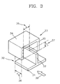
- a 3-dimensional comb structure using an electrostatic force includes at least one fixed comb finger 32 installed perpendicularly on a substrate 31, and at least one movable comb finger 35 which is meshed with the fixed comb finger 32, opposite to the fixed comb finger 32.
- the fixed comb finger 32 and the movable comb finger 35 are spaced apart by a gap s , and overlap with each other by a distance h in a perpendicular direction with respect to the substrate 31.
- a pair of comb fingers 32 and 35 are electrically connected to each other, as shown in FIG. 3, such that they are driven by an electrical field which is generated between them by a voltage provided from a power supply means 36.
- Equation 2 the capacitance of the capacitor formed at this time is expressed by the following Equation 2: wherein ⁇ 0 , s , h , and x denote the permittivity of a gap, the gap between comb fingers, the length by which a pair of comb fingers overlap each other perpendicularly with respect to a substrate, and the length by which a pair of comb fingers overlap each other in parallel to the substrate, respectively. Since the gap s exists between two comb fingers, as shown in FIG. 3, an energy U stored in the capacitor is expressed by the following Equation 3 using the capacitance given by Equation 2:
- Equation 4 A force F which is applied to the movable comb finger 32 and the fixed comb finger 35 parallel to the substrate 31, that is, in a direction indicated by arrow 39 in FIG. 3, is given by the following Equation 4:
- Equation 4 calculates the electrostatic force between the movable comb finger 32 and the fixed comb finger 35 with reference to the basic conceptual diagram showing the operational principle of a 3-dimensional comb structure according to the present invention shown in FIG. 3. It can be seen from Equation 4 that the electrostatic force F acts in a perpendicular direction to the movable comb finger 32 and the fixed comb finger 35, that is, in the direction 39 parallel to the substrate 31.
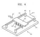
- FIG. 4 which shows an embodiment of a straight-vibrating driver using the 3-dimensional comb structure of FIG. 3, a suspension structure 42 has a plurality of movable comb fingers 43 which protrude perpendicularly thereto, and supported by a substrate via a plurality of support springs 44 and a plurality of supporters 45.
- a plurality of fixed comb fingers 46 are arranged opposite to and in mesh with the movable comb fingers 43, and supported by the substrate 41.
- This 3-dimensional comb structure is driven by an electrostatic force, as described with reference to FIG. 3.
- the vertical width of the support springs 44 is made larger than the horizontal width thereof with respect to the substrate, such that each of the support springs 44 moves with a flexible elasticity in a horizontal direction indicated by arrow 47, and is fixed without flexibility in the vertical direction. That is, when the vertical width of the support spring in FIG. 4 is h , the horizontal width thereof is b , the length thereof is L, and the rigidity thereof is K, the rigidity in an excitation direction and that in a measuring direction are expressed by the following Equation 5:
- Equation 5 the horizontal rigidity and the vertical rigidity of the support spring 44 are proportional to the cube of the horizontal width and the cube of the vertical width, respectively.
- the support spring 44 allows the suspension structure 42 to reciprocate in the directions indicated by double-headed arrow 47 according to the applied alternating current voltage while supporting the suspension structure 42.
- the plurality of supporters 45 are electrically insulated from the substrate 41.
- combs are installed on both ends of a mass body, such that the number of comb fingers can be increased in proportion to the length of the mass body.
- comb fingers protrude perpendicularly with respect to the mass body, such that the number of comb fingers can be increased in proportion to the area of the mass body. Therefore, the 3-dimensional comb structure according to the present invention can increase the number of comb fingers per unit area as compared to the existing comb structure shown in FIG. 2, so that it becomes much stronger.
- This structure is used in various actuators and inertial detection sensors.
- An acceleration detection sensor can be taken as an example of an inertia detection sensor which adopts the 3-dimensional comb structure using an electrostatic force.
- the suspension structure 42 in the comb structure of FIG. 4 is spaced from the substrate 41 by a given distance, such that it can move in the horizontal direction 47 with respect to the substrate 41.
- the suspension structure 42 moves in the direction indicated by arrow x .
- This motion is sensed as a capacitance change caused by the movable comb fingers 43 and the fixed comb fingers 46, thereby detecting the variation in acceleration.
- a gyro sensor can be taken as another example of an inertia detection sensor which adopts the 3-dimensional comb structure using an electrostatic force. While the suspension structure 42 in FIG. 4 moves in the horizontal direction 47 with respect to the substrate 41, a Coriolis force in a direction indicated by arrow z is generated when an acceleration is applied in a direction indicated by arrow y , thus vibrating the suspension structure 42 in the direction indicated by arrow z . This vibration is sensed by an appropriate sensor (not shown in FIG. 4), thereby detecting the applied acceleration.
- the 3-dimensional comb structure using an electrostatic force according to the present invention can also be used in a variety of actuators for moving a suspension structure which is an inertia body, and in various inertial sensors and magnetic flux detection sensors.
- FIG. 5 is a schematic view illustrating a rotary driving structure 50 taken as an example of still another embodiment of the 3-dimensional comb structure according to the present invention.
- a rotary suspension structure 52 has a plurality of movable comb fingers 53 which protrude perpendicularly with respect to the rotatory suspension structure 52, and is supported by a substrate 51 while maintaining a predetermined distance from the substrate 51 via a plurality of support springs 55 and a plurality of supporters 56.
- At least one fixed comb finger 54 which is installed in opposite to and mesh with the movable comb fingers 53, stands perpendicularly on the substrate 51.
- the operational principle of this comb structure is similar to that of the aforementioned comb structure.
- FIG. 6 in which the supporter is positioned at the center of a rotary mass body, is the same as that of the structure shown in FIG. 5.
- the structures shown in FIGS. 5 and 6 can be used in various actuators and sensors according to the principle described in the latter part of the description of the structure shown in FIG. 4.
- a suspension structure which is an inertia body, is separated a predetermined height from a substrate, maintaining the predetermined height from the substrate.
- a movable comb which has at least one movable comb finger, protrudes perpendicularly from the suspension structure.
- a fixed comb which has at least one fixed comb finger, protrudes perpendicularly from the substrate, in mesh with the movable comb.
- the 3-dimensional comb structure is driven by a voltage provided from a power supply unit which is connected to the movable comb and the fixed comb, so that the actuator and the inertial detection sensor both using the 3-dimensional comb structure can obtain the following effects.
- the present invention can greatly increase the number of comb fingers per unit area as compared to an existing driver.
- the present invention can reinforce an electrostatic force greater than an existing comb driver.
- the direction of an electrostatic force in the existing comb structure is the same as that of the protrusion of comb fingers, whereas the direction of an electrostatic force in the 3-dimensional comb driver according to the present invention is perpendicular to that of protrusion of comb fingers.
- the 3-dimensional comb driver according to the present invention is stronger than the existing comb driver, so that it can increase the driving displacement by which a suspension structure is driven.
- the suspension structure can be driven at an arbitrary frequency without the need to drive the suspension structure at the resonance point of the comb structure to move the comb structure. Therefore, when a sensor using the resonance such as microgyro is manufactured using the comb structure according to the present invention, a resonance frequency in the excitation direction of the structure does not need to be consistent with a resonance frequency in the sensing direction thereof.
- the comb driver according to the present invention can generate a sufficiently large force at a small amount of driving voltage, so that the comb structure according to the present invention can be driven with a lower voltage than the existing comb driver.
Landscapes
- Physics & Mathematics (AREA)
- General Physics & Mathematics (AREA)
- Engineering & Computer Science (AREA)
- Computer Hardware Design (AREA)
- Microelectronics & Electronic Packaging (AREA)
- Radar, Positioning & Navigation (AREA)
- Remote Sensing (AREA)
- Micromachines (AREA)
- Gyroscopes (AREA)
- Measurement Of Mechanical Vibrations Or Ultrasonic Waves (AREA)
- Escalators And Moving Walkways (AREA)
- Mechanical Light Control Or Optical Switches (AREA)
- Apparatus Associated With Microorganisms And Enzymes (AREA)
Abstract
Description
- The present invention relates to a 3-dimensional comb structure using an electrostatic force, and an inertia detection sensor and an actuator which uses the 3-dimensional comb structure.
- A 3-dimensional comb structure using an electrostatic force protrudes perpendicularly with respect to a flat plane surface, and has a structure such that an electrostatic force, which is generated between a pair of interlocked combs by applying a voltage thereto, is constant with respect to the relative motion between the combs.
- In many cases, electrostatic actuators are used to move micro structures. An electrostatic comb drive (U.S. Patent No. 5,025,346) is well known as an electrostatic actuator. The basic principle of the electrostatic comb drive will now be described with reference to FIG. 1.
- A pair of
combs power supply 3 is connected to each of thecombs conductive wires comb 2 is expressed by the following Equation 1:wherein ε0, t, s and V denote the permittivity of free space, the thickness of a finger in a direction perpendicular to the surface, the interval between a finger of the
comb 1 and an adjacent finger of thecomb 2, and avoltage 3 applied to a bridge between fingers, respectively. The electrostatic comb drive can be manufactured by a CMOS process such as a process for manufacturing a semiconductor RAM, and has a constant force with respect to the motion of a comb, as shown inEquation 1. - FIG. 2 disclosed in Patent No. 5,025,346 can be taken as an example of an actuator using the principle of FIG. 1, which is the principle of an existing electrostatic comb drive. This
electrostatic actuator 20 includes amass body 22 having a plurality ofmovable comb fingers 27, at least oneelastic member 23 connected to themass body 22, and a plurality of fixedcombs 25 which are meshed with themovable comb fingers 27, facing themovable comb fingers 27. Here, the plurality ofmovable comb fingers 27 are supported by asubstrate 21 viasupporters 24, and the fixedcomb fingers 25 are supported by thesubstrate 21 viafixed comb supporters 26. When a voltage is applied to the fixedcomb fingers 25 and themovable comb fingers 27 via an appropriate means (not shown), themass body 22 is moved linearly in a horizontal direction with respect to thesubstrate 21 by the electrostatic force generated byEquation 1. The electrostatic force generated in this structure is constant with respect to the distance of motion, as shown inEquation 1. However, according to this structure, themovable comb fingers 27 and the fixedcomb fingers 25 are parallel to thesubstrate 21. Also, since themovable comb fingers 27 and the fixedcomb fingers 25 are installed on both ends of the flat mass body which is parallel to thesubstrate 21, the number of combs can increase in proportion to the length of each end of the mass body. Thus, an electrostatic force is small due to the limit in the number of combs. Furthermore, the mass body must move largely to be used in acceleration sensors or gyro sensors. However, in this conventional comb structure, a small amount of electrostatic force makes it difficult to directly drive the mass body, so that the mass body can only be driven at the resonance point. - According to a first aspect of the present invention, there is provided a 3-dimensional comb structure including: a substrate; a suspension structure separated a predetermined height from the substrate, maintaining the predetermined height therefrom, such that the suspension structure can vibrate over the substrate to detect an inertial movement; at least one elastic member connected to the suspension structure, for supporting the suspension structure so that the suspension structure makes an inertial movement; a movable comb having at least one comb finger, the movable comb protruding from the suspension structure; and a fixed comb having at least one comb finger, the fixed comb fingers protruding from the substrate opposite to and in mesh with the movable comb fingers.
- The present invention provides a 3-dimensional comb structure which is strong enough to drive a large-sized structure and having fingers arranged perpendicularly over a flat plane to make it easy to control the position of the structure.
- In the present invention, preferably, an electrostatic force is generated perpendicular to the direction of protrusion of the movable comb fingers from the suspension structure, when a voltage is applied to the movable comb and the fixed comb, so that the 3-dimensional comb structure is excited parallel to the substrate. It is preferable that the movable comb is meshed with the fixed comb having a predetermined gap between a finger of the movable comb and a finger of the fixed comb.
- It is also preferable that the movable comb and the fixed comb face each other, and are arranged on the suspension structure and the substrate, respectively, in a circular symmetrical manner, such that the suspension structure is horizontal to the substrate and rotates around the center of the circular symmetry.
- According to a second aspect of the present invention, there is provided an inertia detection sensor adopting a 3-dimensional comb structure including: a substrate; a suspension structure separated a predetermined height from the substrate, maintaining the predetermined height therefrom, such that the suspension structure can vibrate over the substrate to detect an inertial movement; at least one elastic member connected to the suspension structure, for supporting the suspension structure so that the suspension structure makes an inertial movement; a movable comb having at least one comb finger, the movable comb protruding from the suspension structure; a fixed comb having at least one comb finger, the fixed comb fingers protruding from the substrate opposite to and in mesh with the movable comb fingers; and a sensing unit for detecting an acceleration by sensing a capacity change between the movable comb and the fixed comb.
- Preferably, an electrostatic force is generated perpendicular to the direction of protrusion of the movable comb fingers from the suspension structure, when a voltage is applied to the movable comb and the fixed comb, so that the 3-dimensional comb structure is excited parallel to the substrate. It is preferable that the movable comb is meshed with the fixed comb having a predetermined gap between a finger of the movable comb and a finger of the fixed comb.
- It is also preferable that the movable comb and the fixed comb face each other, and are arranged on the suspension structure and the substrate, respectively, in a circular symmetrical manner, such that the suspension structure is horizontal to the substrate and rotates around the center of the circular symmetry.
- According to a third aspect of the present invention, there is provided an actuator adopting a 3-dimensional comb structure comprising: a substrate; a suspension structure separated a predetermined height from the substrate, maintaining the predetermined height therefrom, such that the suspension structure can vibrate over the substrate to detect an inertial movement; at least one elastic member connected to the suspension structure, for supporting the suspension structure so that the suspension structure makes an inertial movement; a movable comb having at least one comb finger, the movable comb protruding from the suspension structure; a fixed comb having at least one comb finger, the fixed comb fingers protruding from the substrate opposite to and in mesh with the movable comb fingers; and a power supply for providing a voltage between the movable comb and the fixed comb to excite the suspension structure.
- Preferably, an electrostatic force is generated perpendicular to the direction of protrusion of the movable comb fingers from the suspension structure, when a voltage is applied to the movable comb and the fixed comb, so that the 3-dimensional comb structure is excited perpendicular to the direction of protrusion of the fixed comb. It is preferable that the movable comb is meshed with the fixed comb having a predetermined gap between a finger of the movable comb and a finger of the fixed comb.
- Examples of the present invention will now be described in detail with reference to the accompanying drawings, in which:
- FIG. 1 is a plan view schematically illustrating the configuration of a conventional comb structure using an electrostatic force;
- FIG. 2 is a perspective view illustrating an embodiment of an actuator employing the comb structure of FIG. 1;
- FIG. 3 is a perspective view illustrating the basic structure of a 3-dimensional comb structure which is used in an inertia detection sensor and an actuator according to the present invention;
- FIG. 4 is a perspective view illustrating an embodiment of a straight-forwarding actuator using the 3-dimensional comb structure of FIG. 3;
- FIG. 5 is a plan view illustrating an embodiment of a rotary 3-dimensional comb structure which is used in an inertia detection sensor and an actuator according to the present invention; and
- FIG. 6 is a plan view illustrating another embodiment of the rotary 3-dimensional comb structure of FIG. 5.
-
- Referring to FIG. 3, a 3-dimensional comb structure using an electrostatic force according to the present invention includes at least one fixed
comb finger 32 installed perpendicularly on asubstrate 31, and at least onemovable comb finger 35 which is meshed with the fixedcomb finger 32, opposite to the fixedcomb finger 32. The fixedcomb finger 32 and themovable comb finger 35 are spaced apart by a gap s, and overlap with each other by a distance h in a perpendicular direction with respect to thesubstrate 31. A pair ofcomb fingers - As shown in FIG. 3, when a voltage is applied from the power supply means 36, a capacitor is formed between the fixed
comb finger 32 and themovable comb finger 35, so that energies are stored by charge. The capacitance C of the capacitor formed at this time is expressed by the following Equation 2:wherein ε0, s, h, and x denote the permittivity of a gap, the gap between comb fingers, the length by which a pair of comb fingers overlap each other perpendicularly with respect to a substrate, and the length by which a pair of comb fingers overlap each other in parallel to the substrate, respectively. Since the gap s exists between two comb fingers, as shown in FIG. 3, an energy U stored in the capacitor is expressed by the following
Equation 3 using the capacitance given by Equation 2:
- A force F which is applied to the
movable comb finger 32 and the fixedcomb finger 35 parallel to thesubstrate 31, that is, in a direction indicated byarrow 39 in FIG. 3, is given by the following Equation 4:
-
Equation 4 calculates the electrostatic force between themovable comb finger 32 and the fixedcomb finger 35 with reference to the basic conceptual diagram showing the operational principle of a 3-dimensional comb structure according to the present invention shown in FIG. 3. It can be seen fromEquation 4 that the electrostatic force F acts in a perpendicular direction to themovable comb finger 32 and the fixedcomb finger 35, that is, in thedirection 39 parallel to thesubstrate 31. - An embodiment of the 3-dimensional comb structure using an electrostatic force having such a configuration will now be described with reference to FIG. 4. Referring to FIG. 4, which shows an embodiment of a straight-vibrating driver using the 3-dimensional comb structure of FIG. 3, a
suspension structure 42 has a plurality ofmovable comb fingers 43 which protrude perpendicularly thereto, and supported by a substrate via a plurality ofsupport springs 44 and a plurality ofsupporters 45. A plurality of fixedcomb fingers 46 are arranged opposite to and in mesh with themovable comb fingers 43, and supported by thesubstrate 41. This 3-dimensional comb structure is driven by an electrostatic force, as described with reference to FIG. 3. Here, the vertical width of thesupport springs 44 is made larger than the horizontal width thereof with respect to the substrate, such that each of thesupport springs 44 moves with a flexible elasticity in a horizontal direction indicated byarrow 47, and is fixed without flexibility in the vertical direction. That is, when the vertical width of the support spring in FIG. 4 is h, the horizontal width thereof is b, the length thereof is L, and the rigidity thereof is K, the rigidity in an excitation direction and that in a measuring direction are expressed by the following Equation 5:
- It can be seen from
Equation 5 that the horizontal rigidity and the vertical rigidity of thesupport spring 44 are proportional to the cube of the horizontal width and the cube of the vertical width, respectively. - When a voltage is applied from a power supply means (not shown) to the
movable comb fingers 43 and the fixedcomb fingers 46, a capacitance as given byEquation 2 is formed between themovable comb fingers 43 and the fixedcomb fingers 46. Also, the force given byEquation 4 is generated in a direction which is parallel to the substrate, thus moving thesuspension structure 42 to the right. Here, when the voltage from the power supply means (not shown) is an alternating current voltage, thesupport spring 44 allows thesuspension structure 42 to reciprocate in the directions indicated by double-headed arrow 47 according to the applied alternating current voltage while supporting thesuspension structure 42. In order to achieve this operation, it is preferable that the plurality ofsupporters 45 are electrically insulated from thesubstrate 41. - In an existing comb structure, combs are installed on both ends of a mass body, such that the number of comb fingers can be increased in proportion to the length of the mass body. On the other hand, in the 3-dimensional comb structure according to the present invention, comb fingers protrude perpendicularly with respect to the mass body, such that the number of comb fingers can be increased in proportion to the area of the mass body. Therefore, the 3-dimensional comb structure according to the present invention can increase the number of comb fingers per unit area as compared to the existing comb structure shown in FIG. 2, so that it becomes much stronger. This structure is used in various actuators and inertial detection sensors.
- An acceleration detection sensor can be taken as an example of an inertia detection sensor which adopts the 3-dimensional comb structure using an electrostatic force. The
suspension structure 42 in the comb structure of FIG. 4 is spaced from thesubstrate 41 by a given distance, such that it can move in thehorizontal direction 47 with respect to thesubstrate 41. At this time, when an acceleration in a direction indicated by arrow x is applied, thesuspension structure 42 moves in the direction indicated by arrow x. This motion is sensed as a capacitance change caused by themovable comb fingers 43 and the fixedcomb fingers 46, thereby detecting the variation in acceleration. - A gyro sensor can be taken as another example of an inertia detection sensor which adopts the 3-dimensional comb structure using an electrostatic force. While the
suspension structure 42 in FIG. 4 moves in thehorizontal direction 47 with respect to thesubstrate 41, a Coriolis force in a direction indicated by arrow z is generated when an acceleration is applied in a direction indicated by arrow y, thus vibrating thesuspension structure 42 in the direction indicated by arrow z. This vibration is sensed by an appropriate sensor (not shown in FIG. 4), thereby detecting the applied acceleration. - The 3-dimensional comb structure using an electrostatic force according to the present invention can also be used in a variety of actuators for moving a suspension structure which is an inertia body, and in various inertial sensors and magnetic flux detection sensors.
- FIG. 5 is a schematic view illustrating a
rotary driving structure 50 taken as an example of still another embodiment of the 3-dimensional comb structure according to the present invention. In this embodiment which is a structure which can apply a force to a circular structure, arotary suspension structure 52 has a plurality ofmovable comb fingers 53 which protrude perpendicularly with respect to therotatory suspension structure 52, and is supported by asubstrate 51 while maintaining a predetermined distance from thesubstrate 51 via a plurality of support springs 55 and a plurality ofsupporters 56. At least onefixed comb finger 54, which is installed in opposite to and mesh with themovable comb fingers 53, stands perpendicularly on thesubstrate 51. The operational principle of this comb structure is similar to that of the aforementioned comb structure. - When a voltage is applied from a power supply means (not shown) to the
movable comb fingers 53 and at least onefixed comb finger 54, a capacitance as given byEquation 2 is formed between the movable comb fingers and the fixed comb finger, and a force given byEquation 4 is generated parallel to the substrate, thus rotating therotary suspension structure 52. Here, when the voltage applied from the power supply means is an alternating current voltage, asupport spring 55 allows therotary suspension structure 52 to reciprocate a circular arc section having a predetermined angle according to the applied alternating current voltage, while supporting therotary suspension structure 52. In order to achieve this operation, it is preferable that thesupporters 56 are electrically insulated from thesubstrate 51 to prevent flow of current. The operational principle of FIG. 6, in which the supporter is positioned at the center of a rotary mass body, is the same as that of the structure shown in FIG. 5. The structures shown in FIGS. 5 and 6 can be used in various actuators and sensors according to the principle described in the latter part of the description of the structure shown in FIG. 4. - As described above, in a 3-dimensional comb structure according to the present invention and an inertial detection sensor and an actuator both using the 3-dimensional comb structure, a suspension structure, which is an inertia body, is separated a predetermined height from a substrate, maintaining the predetermined height from the substrate. A movable comb, which has at least one movable comb finger, protrudes perpendicularly from the suspension structure. A fixed comb, which has at least one fixed comb finger, protrudes perpendicularly from the substrate, in mesh with the movable comb. The 3-dimensional comb structure is driven by a voltage provided from a power supply unit which is connected to the movable comb and the fixed comb, so that the actuator and the inertial detection sensor both using the 3-dimensional comb structure can obtain the following effects.
- Firstly, since comb fingers are manufactured perpendicular to the suspension structure and the substrate, the present invention can greatly increase the number of comb fingers per unit area as compared to an existing driver. Thus, the present invention can reinforce an electrostatic force greater than an existing comb driver.
- Secondly, the direction of an electrostatic force in the existing comb structure is the same as that of the protrusion of comb fingers, whereas the direction of an electrostatic force in the 3-dimensional comb driver according to the present invention is perpendicular to that of protrusion of comb fingers.
- Thirdly, the 3-dimensional comb driver according to the present invention is stronger than the existing comb driver, so that it can increase the driving displacement by which a suspension structure is driven.
- Fourthly, since the comb structure according to the present invention is strong, the suspension structure can be driven at an arbitrary frequency without the need to drive the suspension structure at the resonance point of the comb structure to move the comb structure. Therefore, when a sensor using the resonance such as microgyro is manufactured using the comb structure according to the present invention, a resonance frequency in the excitation direction of the structure does not need to be consistent with a resonance frequency in the sensing direction thereof.
- Fifthly, the comb driver according to the present invention can generate a sufficiently large force at a small amount of driving voltage, so that the comb structure according to the present invention can be driven with a lower voltage than the existing comb driver.
Claims (10)
- A 3-dimensional comb structure comprising:a substrate;a suspension structure separated a predetermined height from the substrate, maintaining the predetermined height therefrom, such that the suspension structure can vibrate over the substrate;at least one elastic member connected to the suspension structure, for supporting the suspension structure so that the suspension structure makes an inertial movement;a movable comb having at least one comb finger, the movable comb protruding from the suspension structure; anda fixed comb having at least one comb finger, the fixed comb fingers protruding from the substrate opposite to and in mesh with the movable comb fingers.
- A 3-dimensional comb structure according to claim 1, wherein an electrostatic force is generated perpendicular to the direction of protrusion of the movable comb fingers from the suspension structure, when a voltage is applied to the movable comb and the fixed comb, so that the 3-dimensional comb structure is excited parallel to the substrate.
- A 3-dimensional comb structure according to claim 1 or 2, wherein the movable comb is meshed with the fixed comb having a predetermined gap between a finger of the movable comb and a finger of the fixed comb.
- A 3-dimensional comb structure according to any preceding claim, wherein the suspension structure and the movable comb are incorporated into a single body, and make horizontal vibration with respect to the substrate.
- A 3-dimensional comb structure according to any preceding claim, wherein the movable comb and the fixed comb face each other, and are arranged on the suspension structure and the substrate, respectively, in a circular symmetrical manner, such that the suspension structure is horizontal to the substrate and rotates around the center of the circular symmetry.
- A 3-dimensional comb structure according to any preceding claim, wherein the movable comb protrudes perpendicularly from the suspension structure, and the fixed comb protrudes perpendicularly from the substrate.
- A 3-dimensional comb structure according to any preceding claim, wherein the interval between the movable comb and the fixed comb is constant.
- A 3-dimensional comb structure according to any preceding claim, wherein an electrostatic force, which is generated according to a change in the relative distance between the movable comb and the fixed comb, is constant when a constant voltage is applied between the movable comb and the fixed comb.
- An inertia detection sensor comprising a 3-dimensional comb structure according to any preceding claim and a sensing unit for detecting an acceleration by sensing a capacity change between the movable comb and the fixed comb.
- An actuator comprising a 3-dimensional comb structure according to any of claims 1 to 8 and a power supply for providing a voltage between the movable comb and the fixed comb to excite the suspension structure.
Applications Claiming Priority (2)
| Application Number | Priority Date | Filing Date | Title |
|---|---|---|---|
| KR9900387 | 1999-01-11 | ||
| KR10-1999-0000387A KR100459887B1 (en) | 1999-01-11 | 1999-01-11 | Inertia detection ion sensor and actuator using 3-dimension comb structure |
Publications (3)
| Publication Number | Publication Date |
|---|---|
| EP1020984A2 true EP1020984A2 (en) | 2000-07-19 |
| EP1020984A3 EP1020984A3 (en) | 2001-11-14 |
| EP1020984B1 EP1020984B1 (en) | 2008-02-27 |
Family
ID=19570925
Family Applications (1)
| Application Number | Title | Priority Date | Filing Date |
|---|---|---|---|
| EP00300067A Expired - Lifetime EP1020984B1 (en) | 1999-01-11 | 2000-01-07 | A 3-dimensional comb structure |
Country Status (5)
| Country | Link |
|---|---|
| US (1) | US6308573B1 (en) |
| EP (1) | EP1020984B1 (en) |
| JP (1) | JP3645141B2 (en) |
| KR (1) | KR100459887B1 (en) |
| DE (1) | DE60038137T2 (en) |
Cited By (10)
| Publication number | Priority date | Publication date | Assignee | Title |
|---|---|---|---|---|
| GB2364387A (en) * | 2000-02-15 | 2002-01-23 | Toyota Motor Co Ltd | Vibrating physical quantity detector |
| EP1180493A2 (en) * | 2000-08-18 | 2002-02-20 | Samsung Electronics Co., Ltd. | Micro-actuator and manufacturing method thereof |
| EP1203976A2 (en) * | 2000-11-03 | 2002-05-08 | Samsung Electronics Co., Ltd. | Optical scanner, laser image projector adopting the optical scanner, and method of driving the laser image projector |
| EP1223664A2 (en) * | 2001-01-16 | 2002-07-17 | Agilent Technologies, Inc. (a Delaware corporation) | Actuator with a flexure arrangement to accomodate a long range of motion |
| EP1246215A1 (en) * | 2001-03-29 | 2002-10-02 | Abb Research Ltd. | Microrelay with new construction |
| EP1391882A1 (en) * | 2002-08-23 | 2004-02-25 | Hitachi Global Storage Technologies Netherlands B.V. | Electrostatic mircroactuator with electrically isolated moveable portion and associated drive circuitry |
| EP1591824A3 (en) * | 2004-04-26 | 2006-12-20 | Matsushita Electric Industrial Co., Ltd. | Microactuator |
| CN101310432B (en) * | 2005-11-18 | 2011-10-26 | 阿尔卑斯电气株式会社 | Electrostatic actuator |
| EP3358739A4 (en) * | 2015-10-02 | 2019-05-29 | The University Of Tokyo | Vibration power generation element |
| CN110573835A (en) * | 2017-04-27 | 2019-12-13 | 赛峰集团 | Resonator configured to be incorporated into an inertial angle sensor |
Families Citing this family (18)
| Publication number | Priority date | Publication date | Assignee | Title |
|---|---|---|---|---|
| AU2183700A (en) * | 1998-12-15 | 2000-07-03 | Seagate Technology Llc | Optical microswitch with rotary electrostatic microactuator |
| US6351354B1 (en) * | 1999-05-07 | 2002-02-26 | Seagate Technology Llc | Head to flexure interconnection for disc drive microactuator |
| US7079299B1 (en) * | 2000-05-31 | 2006-07-18 | The Regents Of The University Of California | Staggered torsional electrostatic combdrive and method of forming same |
| US6900575B2 (en) * | 2000-12-28 | 2005-05-31 | Cornell Research Foundation, Inc. | Multiple mechanical resonator parametric device |
| US6894420B2 (en) * | 2002-03-14 | 2005-05-17 | Memx, Inc. | Non-linear actuator suspension for microelectromechanical systems |
| EP1375416B1 (en) * | 2002-06-20 | 2007-10-24 | STMicroelectronics S.r.l. | Micro-electro-mechanical device, in particular micro-actuator for hard-disk drive, and manufacturing process thereof |
| US6556415B1 (en) * | 2002-06-28 | 2003-04-29 | Industrial Technologies Research Institute | Tunable/variable passive microelectronic components |
| JP4368739B2 (en) * | 2004-05-21 | 2009-11-18 | アルプス電気株式会社 | Electrostatic suction drive device |
| US7211924B2 (en) * | 2004-05-21 | 2007-05-01 | Alps Electric Co., Ltd. | Electrostatic attraction driving apparatus |
| US7623142B2 (en) * | 2004-09-14 | 2009-11-24 | Hewlett-Packard Development Company, L.P. | Flexure |
| JP2006149140A (en) * | 2004-11-24 | 2006-06-08 | Alps Electric Co Ltd | Electrostatic attraction driving device |
| US7583006B2 (en) * | 2005-07-26 | 2009-09-01 | Siimpel Corporation | MEMS digital linear actuator |
| JP4621577B2 (en) * | 2005-10-27 | 2011-01-26 | アルプス電気株式会社 | Electrostatic actuator and driving method thereof |
| US7832948B1 (en) | 2007-09-13 | 2010-11-16 | Tessera MEMS Technologies, Inc. | Impulse actuated MEMS devices |
| US8640541B2 (en) * | 2009-05-27 | 2014-02-04 | King Abdullah University Of Science And Technology | MEMS mass-spring-damper systems using an out-of-plane suspension scheme |
| DE102009045421B4 (en) | 2009-10-07 | 2022-11-03 | Robert Bosch Gmbh | Micromechanical structure, method for producing a micromechanical structure and use of a micromechanical structure |
| EP3178322B1 (en) | 2014-07-28 | 2021-11-03 | Sumitomo Chemical Company, Limited | Amide compound and use of same for noxious arthropod control |
| US10241129B1 (en) * | 2014-08-01 | 2019-03-26 | Faez Ba-Tis | MEMS piston-tube based capacitive accelerometer |
Citations (2)
| Publication number | Priority date | Publication date | Assignee | Title |
|---|---|---|---|---|
| US5408355A (en) * | 1991-10-30 | 1995-04-18 | Labor Dr. Hans Steinbichler | Micromechanical transducer |
| US5572057A (en) * | 1993-12-21 | 1996-11-05 | Nippondenso Co., Ltd. | Semiconductor acceleration sensor with movable electrode |
Family Cites Families (11)
| Publication number | Priority date | Publication date | Assignee | Title |
|---|---|---|---|---|
| US5640133A (en) * | 1995-06-23 | 1997-06-17 | Cornell Research Foundation, Inc. | Capacitance based tunable micromechanical resonators |
| US6000280A (en) * | 1995-07-20 | 1999-12-14 | Cornell Research Foundation, Inc. | Drive electrodes for microfabricated torsional cantilevers |
| KR100363247B1 (en) * | 1995-10-28 | 2003-02-14 | 삼성전자 주식회사 | Vibrating structure and method for controlling natural frequency of vibrating structure |
| US5591896A (en) * | 1995-11-02 | 1997-01-07 | Lin; Gang | Solid-state gas sensors |
| JP3090024B2 (en) * | 1996-01-22 | 2000-09-18 | 株式会社村田製作所 | Angular velocity sensor |
| JPH10270719A (en) * | 1997-03-26 | 1998-10-09 | Mitsubishi Materials Corp | Semiconductor inertia sensor and its production |
| KR100252009B1 (en) * | 1997-09-25 | 2000-04-15 | 윤종용 | Micro structure for oscillation and method of controlling resonant frequency and the same and microactuator and micro gyroscope using the same |
| US5959808A (en) * | 1997-12-30 | 1999-09-28 | International Business Machines Corporation | Shielded electrostatic microactuators for magnetic-head positioning such devices |
| US5982585A (en) * | 1997-12-30 | 1999-11-09 | International Business Machines Corporation | Rotary electrostatic microactuator with optimum flexure arrangement |
| KR20000038207A (en) * | 1998-12-04 | 2000-07-05 | Samsung Electronics Co Ltd | Structure having comb using electromagnetic force and actuator and inertia sensing sensor using the same |
| US6175069B1 (en) * | 1999-12-29 | 2001-01-16 | Marie Longacre | Music instruction apparatus |
-
1999
- 1999-01-11 KR KR10-1999-0000387A patent/KR100459887B1/en not_active IP Right Cessation
-
2000
- 2000-01-07 JP JP2000001504A patent/JP3645141B2/en not_active Expired - Fee Related
- 2000-01-07 EP EP00300067A patent/EP1020984B1/en not_active Expired - Lifetime
- 2000-01-07 DE DE60038137T patent/DE60038137T2/en not_active Expired - Fee Related
- 2000-01-10 US US09/479,892 patent/US6308573B1/en not_active Expired - Lifetime
Patent Citations (2)
| Publication number | Priority date | Publication date | Assignee | Title |
|---|---|---|---|---|
| US5408355A (en) * | 1991-10-30 | 1995-04-18 | Labor Dr. Hans Steinbichler | Micromechanical transducer |
| US5572057A (en) * | 1993-12-21 | 1996-11-05 | Nippondenso Co., Ltd. | Semiconductor acceleration sensor with movable electrode |
Cited By (19)
| Publication number | Priority date | Publication date | Assignee | Title |
|---|---|---|---|---|
| GB2364387B (en) * | 2000-02-15 | 2002-06-05 | Toyota Motor Co Ltd | Physical quantity detector apparatus |
| GB2364387A (en) * | 2000-02-15 | 2002-01-23 | Toyota Motor Co Ltd | Vibrating physical quantity detector |
| US6543285B2 (en) | 2000-02-15 | 2003-04-08 | Toyota Jidosha Kabushiki Kaisha | Physical quantity detector apparatus |
| EP1180493A2 (en) * | 2000-08-18 | 2002-02-20 | Samsung Electronics Co., Ltd. | Micro-actuator and manufacturing method thereof |
| US7083737B2 (en) | 2000-08-18 | 2006-08-01 | Samsung Electronics Co., Ltd. | Method for manufacturing a micro-actuator |
| EP1180493A3 (en) * | 2000-08-18 | 2003-01-08 | Samsung Electronics Co., Ltd. | Micro-actuator and manufacturing method thereof |
| US6781279B2 (en) | 2000-08-18 | 2004-08-24 | Samsung Electronics Co., Ltd. | Micro-actuator with interdigitated combs perpendicular to a base |
| EP1203976A3 (en) * | 2000-11-03 | 2004-03-24 | Samsung Electronics Co., Ltd. | Optical scanner, laser image projector adopting the optical scanner, and method of driving the laser image projector |
| EP1203976A2 (en) * | 2000-11-03 | 2002-05-08 | Samsung Electronics Co., Ltd. | Optical scanner, laser image projector adopting the optical scanner, and method of driving the laser image projector |
| EP1223664A2 (en) * | 2001-01-16 | 2002-07-17 | Agilent Technologies, Inc. (a Delaware corporation) | Actuator with a flexure arrangement to accomodate a long range of motion |
| EP1223664A3 (en) * | 2001-01-16 | 2005-03-30 | Agilent Technologies, Inc. (a Delaware corporation) | Actuator with a flexure arrangement to accomodate a long range of motion |
| EP1246215A1 (en) * | 2001-03-29 | 2002-10-02 | Abb Research Ltd. | Microrelay with new construction |
| EP1391882A1 (en) * | 2002-08-23 | 2004-02-25 | Hitachi Global Storage Technologies Netherlands B.V. | Electrostatic mircroactuator with electrically isolated moveable portion and associated drive circuitry |
| EP1591824A3 (en) * | 2004-04-26 | 2006-12-20 | Matsushita Electric Industrial Co., Ltd. | Microactuator |
| US7538471B2 (en) | 2004-04-26 | 2009-05-26 | Panasonic Corporation | Microactuator having increased rigidity with reduced mass |
| CN101310432B (en) * | 2005-11-18 | 2011-10-26 | 阿尔卑斯电气株式会社 | Electrostatic actuator |
| EP3358739A4 (en) * | 2015-10-02 | 2019-05-29 | The University Of Tokyo | Vibration power generation element |
| US10840827B2 (en) | 2015-10-02 | 2020-11-17 | The University Of Tokyo | Vibration energy harvester |
| CN110573835A (en) * | 2017-04-27 | 2019-12-13 | 赛峰集团 | Resonator configured to be incorporated into an inertial angle sensor |
Also Published As
| Publication number | Publication date |
|---|---|
| EP1020984B1 (en) | 2008-02-27 |
| JP2000205939A (en) | 2000-07-28 |
| DE60038137D1 (en) | 2008-04-10 |
| EP1020984A3 (en) | 2001-11-14 |
| KR20000050473A (en) | 2000-08-05 |
| JP3645141B2 (en) | 2005-05-11 |
| US6308573B1 (en) | 2001-10-30 |
| KR100459887B1 (en) | 2004-12-03 |
| DE60038137T2 (en) | 2009-02-26 |
Similar Documents
| Publication | Publication Date | Title |
|---|---|---|
| EP1020984A2 (en) | A 3-dimensional comb structure | |
| KR100928356B1 (en) | Rotational speed sensor | |
| US6918298B2 (en) | Horizontal and tuning fork vibratory microgyroscope | |
| JP4288071B2 (en) | Yaw rate sensor | |
| US5920012A (en) | Micromechanical inertial sensor | |
| KR101100021B1 (en) | Z-axis angular rate sensor | |
| US7191653B2 (en) | Tuning fork vibratory MEMS gyroscope | |
| JP3816996B2 (en) | Vibration structure, actuator provided with vibration structure, and control method of natural frequency of vibration structure | |
| EP0943893B1 (en) | Angular velocity sensor | |
| US8272266B2 (en) | Gyroscopes using surface electrodes | |
| KR101817496B1 (en) | Improved gyroscope structure and gyroscope | |
| JPH08327650A (en) | Rotation-rate sensor | |
| EP1774259A1 (en) | Mems gyroscope with horizontally oriented drive electrodes | |
| WO2013179647A2 (en) | Physical amount sensor | |
| US7155976B2 (en) | Rotation sensing apparatus and method for manufacturing the same | |
| WO2007145113A1 (en) | Inertial sensor | |
| US20110138931A1 (en) | Detection sensor | |
| JPH05248872A (en) | Inertia sensor | |
| WO2013094208A1 (en) | Vibration-type angular velocity sensor | |
| US11846651B2 (en) | Electrostatic actuator and physical quantity sensor | |
| JP6627663B2 (en) | Physical quantity sensor | |
| US20080106168A1 (en) | Mems comb device | |
| CN105917192A (en) | Sensor including moving masses and means for detecting relative movements of the masses | |
| KR100631218B1 (en) | Translational MEMS Gyroscope | |
| JP3873266B2 (en) | 3D angular velocity sensor |
Legal Events
| Date | Code | Title | Description |
|---|---|---|---|
| PUAI | Public reference made under article 153(3) epc to a published international application that has entered the european phase |
Free format text: ORIGINAL CODE: 0009012 |
|
| AK | Designated contracting states |
Kind code of ref document: A2 Designated state(s): CH DE GB LI SE Kind code of ref document: A2 Designated state(s): AT BE CH CY DE DK ES FI FR GB GR IE IT LI LU MC NL PT SE |
|
| AX | Request for extension of the european patent |
Free format text: AL;LT;LV;MK;RO;SI |
|
| RIN1 | Information on inventor provided before grant (corrected) |
Inventor name: CHOI, JAE-JOON, 218-1107 WOOSUNG APT. Inventor name: JEONG, HEE-MOON, 810-1604 SHINJUNG MAEUL Inventor name: LEE, KI BANG, 105-803 KEUMHO APT. Inventor name: KIM, KYU-YONG, 426-601 SHIBEOMDANJI HYUNDAI APT. Inventor name: KANG, SUNG-GYU |
|
| PUAL | Search report despatched |
Free format text: ORIGINAL CODE: 0009013 |
|
| AK | Designated contracting states |
Kind code of ref document: A3 Designated state(s): AT BE CH CY DE DK ES FI FR GB GR IE IT LI LU MC NL PT SE |
|
| AX | Request for extension of the european patent |
Free format text: AL;LT;LV;MK;RO;SI |
|
| RIC1 | Information provided on ipc code assigned before grant |
Free format text: 7H 02N 1/00 A, 7H 01H 59/00 B, 7G 01C 19/56 B, 7G 01P 15/125 B, 7G 01P 15/13 B |
|
| 17P | Request for examination filed |
Effective date: 20020320 |
|
| AKX | Designation fees paid |
Free format text: CH DE GB LI SE |
|
| GRAP | Despatch of communication of intention to grant a patent |
Free format text: ORIGINAL CODE: EPIDOSNIGR1 |
|
| GRAS | Grant fee paid |
Free format text: ORIGINAL CODE: EPIDOSNIGR3 |
|
| GRAA | (expected) grant |
Free format text: ORIGINAL CODE: 0009210 |
|
| AK | Designated contracting states |
Kind code of ref document: B1 Designated state(s): CH DE GB LI SE |
|
| REG | Reference to a national code |
Ref country code: GB Ref legal event code: FG4D |
|
| REG | Reference to a national code |
Ref country code: CH Ref legal event code: EP |
|
| REF | Corresponds to: |
Ref document number: 60038137 Country of ref document: DE Date of ref document: 20080410 Kind code of ref document: P |
|
| REG | Reference to a national code |
Ref country code: SE Ref legal event code: TRGR |
|
| REG | Reference to a national code |
Ref country code: CH Ref legal event code: NV Representative=s name: KIRKER & CIE S.A. |
|
| PLBE | No opposition filed within time limit |
Free format text: ORIGINAL CODE: 0009261 |
|
| STAA | Information on the status of an ep patent application or granted ep patent |
Free format text: STATUS: NO OPPOSITION FILED WITHIN TIME LIMIT |
|
| 26N | No opposition filed |
Effective date: 20081128 |
|
| PGFP | Annual fee paid to national office [announced via postgrant information from national office to epo] |
Ref country code: DE Payment date: 20090123 Year of fee payment: 10 |
|
| PGFP | Annual fee paid to national office [announced via postgrant information from national office to epo] |
Ref country code: GB Payment date: 20090114 Year of fee payment: 10 Ref country code: CH Payment date: 20090114 Year of fee payment: 10 |
|
| PGFP | Annual fee paid to national office [announced via postgrant information from national office to epo] |
Ref country code: SE Payment date: 20090108 Year of fee payment: 10 |
|
| REG | Reference to a national code |
Ref country code: CH Ref legal event code: PL |
|
| GBPC | Gb: european patent ceased through non-payment of renewal fee |
Effective date: 20100107 |
|
| EUG | Se: european patent has lapsed | ||
| PG25 | Lapsed in a contracting state [announced via postgrant information from national office to epo] |
Ref country code: CH Free format text: LAPSE BECAUSE OF NON-PAYMENT OF DUE FEES Effective date: 20100131 Ref country code: LI Free format text: LAPSE BECAUSE OF NON-PAYMENT OF DUE FEES Effective date: 20100131 |
|
| PG25 | Lapsed in a contracting state [announced via postgrant information from national office to epo] |
Ref country code: DE Free format text: LAPSE BECAUSE OF NON-PAYMENT OF DUE FEES Effective date: 20100803 |
|
| PG25 | Lapsed in a contracting state [announced via postgrant information from national office to epo] |
Ref country code: GB Free format text: LAPSE BECAUSE OF NON-PAYMENT OF DUE FEES Effective date: 20100107 |
|
| PG25 | Lapsed in a contracting state [announced via postgrant information from national office to epo] |
Ref country code: SE Free format text: LAPSE BECAUSE OF NON-PAYMENT OF DUE FEES Effective date: 20100108 |