EP1020830A2 - Security Display unit - Google Patents
Security Display unit Download PDFInfo
- Publication number
- EP1020830A2 EP1020830A2 EP99310196A EP99310196A EP1020830A2 EP 1020830 A2 EP1020830 A2 EP 1020830A2 EP 99310196 A EP99310196 A EP 99310196A EP 99310196 A EP99310196 A EP 99310196A EP 1020830 A2 EP1020830 A2 EP 1020830A2
- Authority
- EP
- European Patent Office
- Prior art keywords
- display unit
- unit according
- signal
- goods
- adulterating
- Prior art date
- Legal status (The legal status is an assumption and is not a legal conclusion. Google has not performed a legal analysis and makes no representation as to the accuracy of the status listed.)
- Granted
Links
Images


Classifications
-
- E—FIXED CONSTRUCTIONS
- E05—LOCKS; KEYS; WINDOW OR DOOR FITTINGS; SAFES
- E05G—SAFES OR STRONG-ROOMS FOR VALUABLES; BANK PROTECTION DEVICES; SAFETY TRANSACTION PARTITIONS
- E05G1/00—Safes or strong-rooms for valuables
- E05G1/14—Safes or strong-rooms for valuables with means for masking or destroying the valuables, e.g. in case of theft
-
- A—HUMAN NECESSITIES
- A47—FURNITURE; DOMESTIC ARTICLES OR APPLIANCES; COFFEE MILLS; SPICE MILLS; SUCTION CLEANERS IN GENERAL
- A47F—SPECIAL FURNITURE, FITTINGS, OR ACCESSORIES FOR SHOPS, STOREHOUSES, BARS, RESTAURANTS OR THE LIKE; PAYING COUNTERS
- A47F3/00—Show cases or show cabinets
- A47F3/002—Devices for protection against sunlight or theft
-
- G—PHYSICS
- G08—SIGNALLING
- G08B—SIGNALLING OR CALLING SYSTEMS; ORDER TELEGRAPHS; ALARM SYSTEMS
- G08B15/00—Identifying, scaring or incapacitating burglars, thieves or intruders, e.g. by explosives
- G08B15/02—Identifying, scaring or incapacitating burglars, thieves or intruders, e.g. by explosives with smoke, gas, or coloured or odorous powder or liquid
Definitions
- This invention concerns display units for use with relatively high value but easily damaged goods, and in particular to such a display unit which is protected by a mechanism which detects any unauthorised activity and causes devaluing damage to the goods.
- Security means for valuable goods such as banknotes, credit cards and documents, wherein the goods are defaced or marked with a dye or the like in the event of attempted thefts, are known in the art. Examples of such security devices are described in US 5 156 272, US 4 722 435, US 3 730 110, GB 1 446 711, GB 1 138 104 and WO 90/09504. However, none of these documents teaches the application of such technology to a display unit for such goods such as that described in the present application. Further, the goods may easily be accidentally damaged due to a false alarm.
- a display unit for high value goods comprising a container for visible display and security means for deterring unauthorised removal of the goods, characterised in that the container itself is relatively weak and unarmoured and in that the security means comprise a plurality of detectors arranged to detect different types of unauthorised actions applied to the container, means for adulterating the goods by applying thereto an adulterating agent when triggered to do so by activation of a detector, and a unit to control the actuation of the adulteration step on input from one or more of the detectors.
- the display unit is capable of distinguishing between authorised activity (for example, cleaning of the display unit or its immediate environment, where the display unit is accidentally disturbed) and an attempted theft.
- a warning signal may be provided, in order to avoid further accidental disturbance resulting in actuation of the adulterating step.
- the display unit of the invention is for use with tobacco products, but is equally applicable to pharmaceutical products and other packaged high value goods.
- the adulterating agent may take any form known in the art, provided it is capable of adulterating the goods sufficiently so as to render them unsaleable through their obviously stolen appearance.
- the goods may be adulterated by applying a colouring or marking agent, a highly viscous substance which sticks to the goods, or a substance with an unpleasant odour.
- the adulterating agent is some form of colouring or marking agent, typically a staining liquid or powder, which is capable of penetrating the packaging of the goods, for example the outer plastic film and cardboard packaging of cigarette packages.
- Any appropriate marking agent can be used, provided it has the penetrating ability required for the packaging of the goods in question.
- fluorescent inks used in other security devices for example bank note containers
- an additive is added to the adulterating agent.
- Such an additive may typically be invisible to the naked eye but visible to tracing means, e.g. an ultraviolet lamp.
- tracing means e.g. an ultraviolet lamp.
- a typical example is the security ink disclosed in SE-B-464 132, although such inks need to undergo a minor modification to make them thinner and more penetrating. Such a security ink adheres strongly to the skin and makes it much easier for the police to identify the thief.
- the marking agent does not need to be a complex, expensive chemical agent: a simple edible colouring agent such as caramel or a vegetable dye can be used, as once it has penetrated the folds of the cellulose film package, it is virtually impossible to remove without repackaging the goods.
- the display unit is further provided with clear warning means to deter a theft attempt.
- the display unit can be constructed to have an attractive design and can be made from relatively weak materials.
- the container for visible display is relatively weak and unarmoured; in other words, if the container was made of such materials and was not equipped with security means, it would be insufficient to protect the goods from theft. Examples of possible materials include plastic, aluminium, copper and steel.
- the display unit may be made by any suitable means known in the art, such as moulding and extruding, provided that the unit so produced meets the requirements set out above.
- the display unit may further be provided with internally lit display signs.
- the means for applying the adulterating agent take any form known in the art.
- the means for applying the adulterating agent take the form of pressurised spray containers arranged to be activated electrically or mechanically by the detector system.
- a pressurised container may be punctured, releasing the adulterating agent contained therein.
- an aerosol container activated by the release of a compressed spring such as that disclosed in US 3 730 110, could be used.
- Further possibilities include the use of an explosive device, detonation of which releases the adulterating agent.
- a canister of liquid ink is provided with a gas generator. When activated, the canister becomes pressurised and sprays a marking liquid over the goods, thus staining the packages.
- Examples of such canisters are disclosed in international patent publications WO 83/02975 and WO 92/07159 to Stenild, the contents of which are incorporated herein by reference thereto.
- the display unit is also provided with one or more detectors arranged to detect different types of unauthorised activity. Various types of detectors may be used.
- detectors may be provided to detect tampering with the device by cutting or drilling. Preferably, this may be done by providing with a plurality of detectors at different locations on the display unit, in order to detect unauthorised activity at different locations thereon. For example, when the unit is closed on its front face by a shutter, detectors may be provided in both the upper and the lower half thereof, or alternatively in both the left-hand and the right-hand half. The detectors would sense movement of both halves of the shutter and send an input to the control unit to actuate the adulterating means.
- the display unit is wall-mounted and means may be provided to detect any attempted removal of the unit from its mounting.
- detectors may be, for example, optical beam-detection apparatus, magnetic contacts or microswitches.
- detectors could monitor the removal of goods from the display unit (typically passive IR beam-detection apparatus).
- the device may further be fitted with a lock and a detector may sense any attempt to break or otherwise weaken the locking mechanism.
- means may be provided to sense the breaking of glass.
- a plurality of glass sheets may be provided, each equipped with a glass break detector capable of providing an input to the control unit.
- the sheets are made of tempered glass. Examples of suitable glass break detectors are those available from Alarmtech AB, Sweden.
- means may be provided to detect tampering with the internal circuitry of the display unit (in an attempt to deactivate the adulterating means).
- each is connected independently to the control unit, and a current flows through the circuit.
- Means may be provided to sense the breaking of this current; in the event of this occurring, the control unit will send an output to the remaining means to apply the adulterating agent.
- one or more detectors may be provided to sense vibrations such as drilling, mechanical shock or explosions.
- the vibration detectors may be adapted to detect vibrations of different frequency, amplitude and duration.
- a signal from a single vibration sensor may be detected by several channels so that vibrations within differing ranges of frequency, amplitude and duration (hereinafter 'signature vibrations') may be detected in a single detector.
- the term 'vibration sensor' refers to the actual means for sensing vibration. Any device capable of generating an electrical signal when displaced by mechanical vibrations may be used as the vibration sensor. Examples of suitable materials include a piezoceramic crystal, a microphone, optionally in conjunction with a speaker, a geophone (consisting of a weight moving in a coil), a hydrophone, or an arrangement of optical fibres in conjunction with one or more lasers, controlled by processing means. A piezoceramic crystal is preferred.
- the term 'vibration detector' refers to the whole detector, including the sensor and any processing means/ circuitry to which it is connected.
- 'channel' means for detecting a specific range of frequency, amplitude and duration levels (signature ranges), so that only such signature ranges will be detected and further processed by the detector.
- signature ranges The range of signatures with respect to frequency and/or amplitude levels capable of being detected by each channel may or may not overlap.
- the frequency, amplitude and duration of the signature capable of being detected by each channel may vary depending on the likely means by which theft is attempted and the surrounding conditions.
- the unit may be equipped to detect drilling, in which case the channel may be adapted to detect vibrations of relatively high frequency and long duration, but low amplitude.
- the signature vibration detectable by such a channel is of amplitude corresponding to an acceleration of 0.001 g to 0.5 g , preferably 0.005 g to 0.1 g , and of frequency of 1 kHz to 20 kHz, preferably 3 kHz to 10 kHz.
- the detector may be capable of detecting mechanical shocks.
- the channel may detect vibrations of intermediate amplitude, but relatively low frequency and short duration.
- the signature vibration detectable by such a channel is of frequency of from 0.1 kHz to 10 kHz, preferably from 0.3 kHz to 8 kHz, and amplitude corresponding to an acceleration of between 2 g and 50 g , preferably 5 g to 20 g .
- the detector may detect more powerful mechanical shocks, such as explosions, in which case the channel may detect low-frequency and very high amplitude vibrations.
- the channel may detect low-frequency and very high amplitude vibrations.
- signature vibrations of amplitude corresponding to an acceleration of over 200 g , preferably over 600 g , and of a frequency of from 0.1 kHz to 10 kHz, preferably from 0.3 kHz to 8 kHz.
- the vibration detector may be further provided with means to control its sensitivity, so that environmental noise will be ignored and will not actuate the adulterating step.
- the sensitivity of the unit may be set by testing the unit at differing levels of background noise and ascertaining whether such a level is sufficient to trigger the vibration detector.
- the vibration detector may be capable of transmitting at least three different types of signal to the control unit, said signals hereinafter described as a pulse signal, a warning signal and an alarm signal.
- the three types of signal may be differentiated from one another by any means known in the art, for example by voltage, current or duration.
- a pulse signal may have a duration of less than 30 ms, a warning signal from 30 to 700 ms, and an alarm signal over 700 ms.
- the control unit may be equipped with means to read and differentiate such signals and take the necessary action, the means for doing so being readily apparent to those skilled in the art.
- the vibration detectors may be provided with memory; incoming signals into the detectors may be stored/integrated in the memory. When the signal stored in the memory reaches a pre-programmed value, the vibration detector sends an alarm signal to the control unit to actuate the adulteration step. In this way, a continuous low-amplitude vibration such as drilling, or repeated mechanical shocks over a short space of time, may be detected and the adulteration step actuated accordingly.
- the signal stored in the memory will decay with time once the vibrations have ceased, so that repeated minor shocks or vibrations over the course of a long interval will not actuate the adulterating step.
- means may further be provided to reset the signal stored in the memory to zero.
- the time duration necessary for the signal to decay to zero will vary depending on the channel detecting the vibrations and the environmental conditions. For example, a signal from the drilling detector may take from 10 seconds to 2 minutes, preferably 20 to 40 seconds, to decay.
- the detector tuned to detect vibrations of such a frequency and amplitude may automatically send an alarm signal to the control unit to actuate the adulterating step.
- the vibration detector may further be programmed to provide a warning signal to the control unit when the signal stored in the memory reaches a preset value, typically a value different to that necessary to actuate the adulterating step. On input from such a signal, the display unit issues a warning signal, for example a flash or beep. In this way the display unit may provide a warning signal before actuating the adulterating step.
- a preset value typically a value different to that necessary to actuate the adulterating step.
- the detector When repeated mechanical shocks are applied to the system within a certain time period, the detector will send an alarm signal to the control unit, so that the control unit will activate the adulterating step.
- the display unit may be programmed so as to vary the time period, force and number of mechanical shocks necessary to actuate the adulterating step.
- the device is provided with means for inhibiting the adulteration step in the event of a fault.
- the control unit which senses a fault in the device and may further provide a visible and/or audible warning when the user attempts to arm the device. For example, when the device is closed by shutters, the control unit senses a fault when the shutter is pulled down. If no fault is present, the user is informed by an audible signal and the system is armed. If, however, a fault is present, a different signal is issued and the control unit will not actuate the adulterating step.
- the control unit may typically test for faults several times per second.
- the control unit may be further provided with memory so that each event experienced by the display unit (for example, attempted thefts, services, accidental disturbances, faults) may be recorded.
- the memory is preferably able to record events for a typical time interval between services (about a year).
- the control unit may further be connected to output means such as a screen or printer, so that a service engineer or the like may easily be able to obtain a statement of all events that have taken place.
- the display unit may further be provided with means to detect tampering with the power supply.
- the unit 10 comprises a generally rectangular enclosure provided at the front with a roller shutter 12 at the bottom; the roller shutter 12 is provided with a lock mechanism 14 coupled with a magnetic control switch and/or light sensor. A door sensor 16 is also provided.
- the unit is provided at the back with a wall switch 18 (see Fig. 3) arranged to be actuated if the unit is removed from its fixing on the wall.
- the unit is provided with a series of racks 20 each provided with a dedicated ink pack 22, arranged to spray ink, when actuated, over the contents of the neighbouring rack 20.
- a vibration detector 30 is also provided.
- the various sensors and switches are powered by power supply included in control unit 24, described in more detail below in relation to Fig. 5.
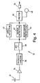
- Fig. 4 illustrates the vibration detector 30 in more detail.
- a piezoceramic crystal 32 is connected to an amplifier 34, which in turn is connected to a potentiometer 36 and a band pass filter 38.
- the band pass filter is further connected to a channel 40 for detecting drilling, channel 42 for detecting mechanical shocks, and channel 44 for detecting explosions, the channels 40, 42, 44 in parallel with one another.
- Channels 40 and 42 are provided with memory.
- the channels are further connected to a driver 46 capable of providing an output to LED 48 and terminal 50, which is capable of providing an output to the control unit.
- Vibrations are received by crystal 32 and converted therein to electrical signals, which are amplified by amplifier 34.
- Potentiometer 36 ensures that only signals of sufficient amplitude pass through to band pass filter 38, so that environmental noise does not trigger the detectors.
- Band pass filter 38 filters out unwanted frequencies so that only signals corresponding to vibrations detectable by detector channels 40, 42, 44 will reach said channels. Further filters may be provided in channels 40, 42, 44.
- vibrations meeting the necessary signature credentials (typically frequency 3 kHz to 10 kHz and amplitude corresponding to an acceleration of 0.005 g to 0.1 g ) pass through band pass filter 38 and are transmitted to channel 40.
- Signals meeting the signature credentials are stored in memory which stores a certain number of samples by means of a shift register or the like. Each time an incoming signal is stored, a pulse signal is issued by channel 40. The control unit recognises this signal but takes no action until a pre-set value is reached.
- channel 40 sends an alarm signal via driver 46 and terminal 50 to the control unit.
- the control unit reads this signal and sends a signal to the adulterating means to actuate the adulterating step.
- Mechanical shock vibrations meeting the "shock" signature criteria (a typical frequency of 0.3 kHz to 8 kHz and of amplitude corresponding to an acceleration of 2 g to 50 g ) also pass through band pass filter 38 and are transmitted to channel 42.
- a signal meeting the shock signature criteria is stored in memory similar to that described above in relation to channel 40, and a warning signal is sent via driver 46 and terminal 50 to the control unit, which recognises this signal and actuates audible and/or visible means to provide a warning.
- Memory allows the time interval between mechanical shocks to be recorded. In the event of several shocks in a short space of time, an alarm signal is sent via driver 46 and terminal 50 to the control unit, which reads such a signal and actuates the adulterating step.
- vibrations of very high amplitude typically corresponding to an acceleration of over 600 g
- vibrations of very high amplitude typically corresponding to an acceleration of over 600 g
- a typical frequency typically from 0.3 kHz to 8 kHz
- Fig. 5 illustrates the control unit 24 in more detail.
- Central control unit 70 is connected to lock 14, door sensor 16 and wall sensor 18.
- Vibration detector 30 is also connected to central control unit 70 via timing control 72 which measures the duration of the signal emitted by vibration detector 72 and sends an appropriate signal to central control unit 70.
- Central control unit 70 is further connected to adulteration control unit 74, which is independently connected to means 76a to 76e for applying the adulterating agent.
- adulteration control unit 74 On receipt of an alarm signal from the central control unit 70, adulteration control unit 74 sends a high-current signal to any or all of means 76a to 76e to apply the agent and adulterate the goods.
- a low-current signal (insufficient to actuate the adulterating means) passes between unit 74 and means 76a to 76e; in the event of tampering with any of means 76a to 76e or their connection with the adulteration control unit 74, the current is broken, a high-current signal is sent to the other means for applying the adulterating agent.
- Central control unit 70 is further connected to power control unit 78 which receives electrical power from mains power supply 80 and/or back-up battery 82. In the event of tampering with the power supply 80 and/or its connection with power control unit 78, a signal may be sent to the central control unit 70, which issues warning and/or alarm signals as the user deems appropriate; until mains power is restored, battery 82 provides back-up.
- the unit is further provided with output control 84, which is connected to warning buzzer 86, alarm buzzer 88, and display 90.
- event memory 92 which is capable of recording each event experienced by the display unit (for example, attempted thefts, services, accidental disturbances, or faults). This may further be connected to event printer 94, so that a service engineer or the like may easily be able to obtain a statement of all events that have taken place.
Abstract
Description
- This invention concerns display units for use with relatively high value but easily damaged goods, and in particular to such a display unit which is protected by a mechanism which detects any unauthorised activity and causes devaluing damage to the goods.
- There are many types of goods sold in shops which are relatively highly priced, but easily portable, thus making them very vulnerable to robbery. A particular example is cigarettes and other tobacco products, especially in countries where the taxation level is very high. Products of this type are generally sold in relatively small packages, which are generally wrapped in card or paperboard containers, generally with an outer clear plastic film, typically a cellulose ester.
- When goods of this kind are stolen from shops, the loss to the shopkeeper is not merely the value of the stock, but includes, as a major part, damage to the premises and to the storage equipment. Conventional solutions to the problem include secure storage units for use when the shop is closed. This is inconvenient as the stock has to be transferred from the day time display unit into the secure store for the night and then set out on display again the following day.
- An alternative solution to the problem involves the use of highly secure display devices themselves. Here, the essential idea is to protect the display unit from being broken into, by making it of a robust construction, e.g. tough sheet steel, and providing it with secure locks. This kind of system is very expensive and tends to be unsightly, or at least unattractive to the customer. The only other possibility has been to protect the shop or display premises by fitting burglar alarms, armoured doors, etc. However, these deterrents do not always deter and it is unfortunately possible to break into premises (for example by ram-raiding with a motor vehicle), steal the goods and escape before a guard or the police arrive.
- Security means for valuable goods such as banknotes, credit cards and documents, wherein the goods are defaced or marked with a dye or the like in the event of attempted thefts, are known in the art. Examples of such security devices are described in US 5 156 272, US 4 722 435, US 3 730 110, GB 1 446 711, GB 1 138 104 and WO 90/09504. However, none of these documents teaches the application of such technology to a display unit for such goods such as that described in the present application. Further, the goods may easily be accidentally damaged due to a false alarm.
- It is therefore an object of the present invention to provide a display unit for goods such as cigarettes which is capable of deterring unauthorised activity, while being attractive to the customer and available at lower cost.
- It is a further object of the present invention to provide a display unit capable of distinguishing between authorised activity and attempted theft.
- According to the invention there is provided a display unit for high value goods comprising a container for visible display and security means for deterring unauthorised removal of the goods, characterised in that the container itself is relatively weak and unarmoured and in that the security means comprise a plurality of detectors arranged to detect different types of unauthorised actions applied to the container, means for adulterating the goods by applying thereto an adulterating agent when triggered to do so by activation of a detector, and a unit to control the actuation of the adulteration step on input from one or more of the detectors.
- Preferably, the display unit is capable of distinguishing between authorised activity (for example, cleaning of the display unit or its immediate environment, where the display unit is accidentally disturbed) and an attempted theft. A warning signal may be provided, in order to avoid further accidental disturbance resulting in actuation of the adulterating step.
- In particular, the display unit of the invention is for use with tobacco products, but is equally applicable to pharmaceutical products and other packaged high value goods.
- The adulterating agent may take any form known in the art, provided it is capable of adulterating the goods sufficiently so as to render them unsaleable through their obviously stolen appearance. For example, the goods may be adulterated by applying a colouring or marking agent, a highly viscous substance which sticks to the goods, or a substance with an unpleasant odour. Preferably the adulterating agent is some form of colouring or marking agent, typically a staining liquid or powder, which is capable of penetrating the packaging of the goods, for example the outer plastic film and cardboard packaging of cigarette packages. Any appropriate marking agent can be used, provided it has the penetrating ability required for the packaging of the goods in question. Typically, fluorescent inks used in other security devices (for example bank note containers) can be used. Preferably, an additive is added to the adulterating agent. Such an additive may typically be invisible to the naked eye but visible to tracing means, e.g. an ultraviolet lamp. A typical example is the security ink disclosed in SE-B-464 132, although such inks need to undergo a minor modification to make them thinner and more penetrating. Such a security ink adheres strongly to the skin and makes it much easier for the police to identify the thief.
- The marking agent does not need to be a complex, expensive chemical agent: a simple edible colouring agent such as caramel or a vegetable dye can be used, as once it has penetrated the folds of the cellulose film package, it is virtually impossible to remove without repackaging the goods.
- Preferably, the display unit is further provided with clear warning means to deter a theft attempt.
- The display unit can be constructed to have an attractive design and can be made from relatively weak materials. The container for visible display is relatively weak and unarmoured; in other words, if the container was made of such materials and was not equipped with security means, it would be insufficient to protect the goods from theft. Examples of possible materials include plastic, aluminium, copper and steel. The display unit may be made by any suitable means known in the art, such as moulding and extruding, provided that the unit so produced meets the requirements set out above. The display unit may further be provided with internally lit display signs.
- Inside the display unit, arranged at appropriate positions, there are provided one or more means for applying the adulterating agent. Such means may take any form known in the art. Typically, the means for applying the adulterating agent take the form of pressurised spray containers arranged to be activated electrically or mechanically by the detector system. For example, a pressurised container may be punctured, releasing the adulterating agent contained therein. Alternatively, an aerosol container activated by the release of a compressed spring, such as that disclosed in US 3 730 110, could be used. Further possibilities include the use of an explosive device, detonation of which releases the adulterating agent.
- In a particularly preferred embodiment, a canister of liquid ink is provided with a gas generator. When activated, the canister becomes pressurised and sprays a marking liquid over the goods, thus staining the packages. Examples of such canisters are disclosed in international patent publications WO 83/02975 and WO 92/07159 to Stenild, the contents of which are incorporated herein by reference thereto.
- The display unit is also provided with one or more detectors arranged to detect different types of unauthorised activity. Various types of detectors may be used.
- In one embodiment, detectors may be provided to detect tampering with the device by cutting or drilling. Preferably, this may be done by providing with a plurality of detectors at different locations on the display unit, in order to detect unauthorised activity at different locations thereon. For example, when the unit is closed on its front face by a shutter, detectors may be provided in both the upper and the lower half thereof, or alternatively in both the left-hand and the right-hand half. The detectors would sense movement of both halves of the shutter and send an input to the control unit to actuate the adulterating means.
- In another embodiment, the display unit is wall-mounted and means may be provided to detect any attempted removal of the unit from its mounting. Such detectors may be, for example, optical beam-detection apparatus, magnetic contacts or microswitches.
- In a further embodiment, detectors could monitor the removal of goods from the display unit (typically passive IR beam-detection apparatus).
- In a still further embodiment, the device may further be fitted with a lock and a detector may sense any attempt to break or otherwise weaken the locking mechanism.
- In a yet further embodiment, means may be provided to sense the breaking of glass. A plurality of glass sheets may be provided, each equipped with a glass break detector capable of providing an input to the control unit. Preferably, the sheets are made of tempered glass. Examples of suitable glass break detectors are those available from Alarmtech AB, Sweden.
- In a still further embodiment, means may be provided to detect tampering with the internal circuitry of the display unit (in an attempt to deactivate the adulterating means). Typically, when a plurality of means for applying the adulterating agent are provided, each is connected independently to the control unit, and a current flows through the circuit. Means may be provided to sense the breaking of this current; in the event of this occurring, the control unit will send an output to the remaining means to apply the adulterating agent.
- In a preferred embodiment, one or more detectors may be provided to sense vibrations such as drilling, mechanical shock or explosions. The vibration detectors may be adapted to detect vibrations of different frequency, amplitude and duration. Preferably, a signal from a single vibration sensor may be detected by several channels so that vibrations within differing ranges of frequency, amplitude and duration (hereinafter 'signature vibrations') may be detected in a single detector.
- It should be noted for the sake of clarity that the term 'vibration sensor' refers to the actual means for sensing vibration. Any device capable of generating an electrical signal when displaced by mechanical vibrations may be used as the vibration sensor. Examples of suitable materials include a piezoceramic crystal, a microphone, optionally in conjunction with a speaker, a geophone (consisting of a weight moving in a coil), a hydrophone, or an arrangement of optical fibres in conjunction with one or more lasers, controlled by processing means. A piezoceramic crystal is preferred. The term 'vibration detector' refers to the whole detector, including the sensor and any processing means/ circuitry to which it is connected.
- By 'channel' is meant means for detecting a specific range of frequency, amplitude and duration levels (signature ranges), so that only such signature ranges will be detected and further processed by the detector. The range of signatures with respect to frequency and/or amplitude levels capable of being detected by each channel may or may not overlap.
- The frequency, amplitude and duration of the signature capable of being detected by each channel may vary depending on the likely means by which theft is attempted and the surrounding conditions.
- For example, the unit may be equipped to detect drilling, in which case the channel may be adapted to detect vibrations of relatively high frequency and long duration, but low amplitude. Typically the signature vibration detectable by such a channel is of amplitude corresponding to an acceleration of 0.001g to 0.5g, preferably 0.005g to 0.1g, and of frequency of 1 kHz to 20 kHz, preferably 3 kHz to 10 kHz.
- Alternatively, the detector may be capable of detecting mechanical shocks. In order to do this, the channel may detect vibrations of intermediate amplitude, but relatively low frequency and short duration. Typically the signature vibration detectable by such a channel is of frequency of from 0.1 kHz to 10 kHz, preferably from 0.3 kHz to 8 kHz, and amplitude corresponding to an acceleration of between 2g and 50g, preferably 5g to 20g.
- As a further alternative, the detector may detect more powerful mechanical shocks, such as explosions, in which case the channel may detect low-frequency and very high amplitude vibrations. Typically such a detector would detect signature vibrations of amplitude corresponding to an acceleration of over 200g, preferably over 600g, and of a frequency of from 0.1 kHz to 10 kHz, preferably from 0.3 kHz to 8 kHz.
- The vibration detector may be further provided with means to control its sensitivity, so that environmental noise will be ignored and will not actuate the adulterating step. Typically, the sensitivity of the unit may be set by testing the unit at differing levels of background noise and ascertaining whether such a level is sufficient to trigger the vibration detector.
- In an especially preferred embodiment, the vibration detector may be capable of transmitting at least three different types of signal to the control unit, said signals hereinafter described as a pulse signal, a warning signal and an alarm signal. The three types of signal may be differentiated from one another by any means known in the art, for example by voltage, current or duration. For example, a pulse signal may have a duration of less than 30 ms, a warning signal from 30 to 700 ms, and an alarm signal over 700 ms.
- The control unit may be equipped with means to read and differentiate such signals and take the necessary action, the means for doing so being readily apparent to those skilled in the art.
- In a particularly preferred embodiment, the vibration detectors may be provided with memory; incoming signals into the detectors may be stored/integrated in the memory. When the signal stored in the memory reaches a pre-programmed value, the vibration detector sends an alarm signal to the control unit to actuate the adulteration step. In this way, a continuous low-amplitude vibration such as drilling, or repeated mechanical shocks over a short space of time, may be detected and the adulteration step actuated accordingly.
- Typically, the signal stored in the memory will decay with time once the vibrations have ceased, so that repeated minor shocks or vibrations over the course of a long interval will not actuate the adulterating step. In addition, means may further be provided to reset the signal stored in the memory to zero. The time duration necessary for the signal to decay to zero will vary depending on the channel detecting the vibrations and the environmental conditions. For example, a signal from the drilling detector may take from 10 seconds to 2 minutes, preferably 20 to 40 seconds, to decay.
- In the event of a more powerful mechanical shock, such as an explosion, the detector tuned to detect vibrations of such a frequency and amplitude may automatically send an alarm signal to the control unit to actuate the adulterating step.
- The vibration detector may further be programmed to provide a warning signal to the control unit when the signal stored in the memory reaches a preset value, typically a value different to that necessary to actuate the adulterating step. On input from such a signal, the display unit issues a warning signal, for example a flash or beep. In this way the display unit may provide a warning signal before actuating the adulterating step.
- When repeated mechanical shocks are applied to the system within a certain time period, the detector will send an alarm signal to the control unit, so that the control unit will activate the adulterating step. The display unit may be programmed so as to vary the time period, force and number of mechanical shocks necessary to actuate the adulterating step.
- In a further embodiment, the device is provided with means for inhibiting the adulteration step in the event of a fault. Typically, this may be done by the control unit, which senses a fault in the device and may further provide a visible and/or audible warning when the user attempts to arm the device. For example, when the device is closed by shutters, the control unit senses a fault when the shutter is pulled down. If no fault is present, the user is informed by an audible signal and the system is armed. If, however, a fault is present, a different signal is issued and the control unit will not actuate the adulterating step. The control unit may typically test for faults several times per second.
- The control unit may be further provided with memory so that each event experienced by the display unit (for example, attempted thefts, services, accidental disturbances, faults) may be recorded. The memory is preferably able to record events for a typical time interval between services (about a year). The control unit may further be connected to output means such as a screen or printer, so that a service engineer or the like may easily be able to obtain a statement of all events that have taken place.
- The display unit may further be provided with means to detect tampering with the power supply.
- A particular embodiment will now be described with reference to the accompanying drawings in which:
- Figure 1 represents a front view of the display unit in the closed position;
- Figure 2 is a front view of the inside of the unit;
- Figure 3 represents a side view of the unit;
- Figure 4 is a schematic diagram showing the vibration detector in more detail; and
- Figure 5 is a schematic diagram showing the control unit in more detail.
-
- Referring first to Fig. 1, the
unit 10 comprises a generally rectangular enclosure provided at the front with aroller shutter 12 at the bottom; theroller shutter 12 is provided with alock mechanism 14 coupled with a magnetic control switch and/or light sensor. Adoor sensor 16 is also provided. The unit is provided at the back with a wall switch 18 (see Fig. 3) arranged to be actuated if the unit is removed from its fixing on the wall. - Internally, the unit is provided with a series of
racks 20 each provided with adedicated ink pack 22, arranged to spray ink, when actuated, over the contents of the neighbouringrack 20. Avibration detector 30 is also provided. The various sensors and switches are powered by power supply included incontrol unit 24, described in more detail below in relation to Fig. 5. - Fig. 4 illustrates the
vibration detector 30 in more detail. Apiezoceramic crystal 32 is connected to anamplifier 34, which in turn is connected to apotentiometer 36 and aband pass filter 38. - The band pass filter is further connected to a
channel 40 for detecting drilling,channel 42 for detecting mechanical shocks, andchannel 44 for detecting explosions, thechannels Channels driver 46 capable of providing an output toLED 48 andterminal 50, which is capable of providing an output to the control unit. - The vibration detector will now be described in use, with reference to the following, non-limiting example.
- Vibrations are received by
crystal 32 and converted therein to electrical signals, which are amplified byamplifier 34.Potentiometer 36 ensures that only signals of sufficient amplitude pass through to bandpass filter 38, so that environmental noise does not trigger the detectors.Band pass filter 38 filters out unwanted frequencies so that only signals corresponding to vibrations detectable bydetector channels channels - In the event of tampering with the display unit by drilling, vibrations meeting the necessary signature credentials (typically frequency 3 kHz to 10 kHz and amplitude corresponding to an acceleration of 0.005g to 0.1g) pass through
band pass filter 38 and are transmitted to channel 40. Signals meeting the signature credentials are stored in memory which stores a certain number of samples by means of a shift register or the like. Each time an incoming signal is stored, a pulse signal is issued bychannel 40. The control unit recognises this signal but takes no action until a pre-set value is reached. - When the vibration received has continued for sufficient duration so that the signal in the memory reaches a value pre-set by the user,
channel 40 sends an alarm signal viadriver 46 and terminal 50 to the control unit. The control unit reads this signal and sends a signal to the adulterating means to actuate the adulterating step. - Mechanical shock vibrations meeting the "shock" signature criteria (a typical frequency of 0.3 kHz to 8 kHz and of amplitude corresponding to an acceleration of 2g to 50g) also pass through
band pass filter 38 and are transmitted to channel 42. A signal meeting the shock signature criteria is stored in memory similar to that described above in relation tochannel 40, and a warning signal is sent viadriver 46 and terminal 50 to the control unit, which recognises this signal and actuates audible and/or visible means to provide a warning. - Memory allows the time interval between mechanical shocks to be recorded. In the event of several shocks in a short space of time, an alarm signal is sent via
driver 46 and terminal 50 to the control unit, which reads such a signal and actuates the adulterating step. - In the event of an explosion, vibrations of very high amplitude (typically corresponding to an acceleration of over 600g), and of a typical frequency from 0.3 kHz to 8 kHz, pass through
band pass filter 40 and are transmitted to channel 44. This issues an alarm signal viadriver 46 and terminal 50 to the control unit, directing it to actuate the adulterating step. - Fig. 5 illustrates the
control unit 24 in more detail.Central control unit 70 is connected to lock 14,door sensor 16 andwall sensor 18. -
Vibration detector 30 is also connected tocentral control unit 70 viatiming control 72 which measures the duration of the signal emitted byvibration detector 72 and sends an appropriate signal tocentral control unit 70. -
Central control unit 70 is further connected toadulteration control unit 74, which is independently connected tomeans 76a to 76e for applying the adulterating agent. On receipt of an alarm signal from thecentral control unit 70,adulteration control unit 74 sends a high-current signal to any or all ofmeans 76a to 76e to apply the agent and adulterate the goods. A low-current signal (insufficient to actuate the adulterating means) passes betweenunit 74 and means 76a to 76e; in the event of tampering with any ofmeans 76a to 76e or their connection with theadulteration control unit 74, the current is broken, a high-current signal is sent to the other means for applying the adulterating agent. -
Central control unit 70 is further connected topower control unit 78 which receives electrical power frommains power supply 80 and/or back-upbattery 82. In the event of tampering with thepower supply 80 and/or its connection withpower control unit 78, a signal may be sent to thecentral control unit 70, which issues warning and/or alarm signals as the user deems appropriate; until mains power is restored,battery 82 provides back-up. - The unit is further provided with
output control 84, which is connected to warningbuzzer 86,alarm buzzer 88, anddisplay 90. Also provided isevent memory 92 which is capable of recording each event experienced by the display unit (for example, attempted thefts, services, accidental disturbances, or faults). This may further be connected toevent printer 94, so that a service engineer or the like may easily be able to obtain a statement of all events that have taken place.
Claims (18)
- A display unit for high value goods comprising a container for visible display and security means for deterring unauthorised removal of the goods, characterised in that the container itself is relatively weak and unarmoured and in that the security means comprise a plurality of detectors arranged to detect different types of unauthorised actions applied to the container, means for adulterating the goods by applying thereto an adulterating agent when triggered to do so by activation of a detector, and a unit to control the actuation of the adulteration step on input from one or more of the detectors.
- A display unit according to claim 1, which is capable of distinguishing between authorised activity and an attempted theft.
- A display unit according to claim 1 or claim 2, which is capable of providing a warning signal.
- A display unit according to any one of the preceding claims, provided with means for detecting vibration.
- A display unit according to claim 4, wherein the vibration detector is adapted to detect vibrations of different amplitude, frequency and duration.
- A display unit according to claim 5, wherein a signal from a single vibration sensor may be detected by several channels so that vibrations within differing ranges of frequency, amplitude and duration may be detected in a single vibration detector.
- A display unit according to any one of claims 4 to 6, wherein the vibration detector is provided with memory.
- A display unit according to any one of claims 4 to 7, wherein the vibration detector is capable of providing at least a pulse signal, a warning signal and an alarm signal to the control unit.
- A display unit according to claim 8, wherein the vibration detector provides an alarm signal when the signal in the memory reaches a pre-set value.
- A display unit according to claim 8, wherein the vibration detector provides a warning signal when the signal in the memory reaches a pre-set value.
- A display unit according to any one of the preceding claims, provided with a plurality of glass sheets, each sheet being provided with a glass break detector capable of providing an input to the control unit.
- A display unit according to any one of the preceding claims, wherein the detectors are positioned at different locations thereon in order to detect unauthorised entry at different locations.
- A display unit according to any one of the preceding claims, in which the adulterating agent is a marking or staining liquid or powder.
- A display unit according to claim 13, in which an additive is added to the adulterating agent, said additive being invisible to the naked eye but visible to tracing means.
- A display unit according to any one of the preceding claims, which the means for adulterating the goods comprises a canister of liquid ink coupled to one or more gas generators.
- A display unit according to any one of the preceding claims, further provided with means for informing the user and inhibiting the adulteration step in the event of a fault when the user attempts to arm the unit.
- A display unit according to any one of the preceding claims, provided with means to detect tampering with the internal circuitry thereof.
- A display unit according to any one of the preceding claims, in which the high value goods are tobacco products.
Applications Claiming Priority (2)
| Application Number | Priority Date | Filing Date | Title |
|---|---|---|---|
| GB9828033A GB2344811A (en) | 1998-12-18 | 1998-12-18 | Security display unit |
| GB9828033 | 1998-12-18 |
Publications (3)
| Publication Number | Publication Date |
|---|---|
| EP1020830A2 true EP1020830A2 (en) | 2000-07-19 |
| EP1020830A3 EP1020830A3 (en) | 2001-04-18 |
| EP1020830B1 EP1020830B1 (en) | 2003-04-09 |
Family
ID=10844582
Family Applications (1)
| Application Number | Title | Priority Date | Filing Date |
|---|---|---|---|
| EP99310196A Expired - Lifetime EP1020830B1 (en) | 1998-12-18 | 1999-12-16 | Security Display unit |
Country Status (6)
| Country | Link |
|---|---|
| EP (1) | EP1020830B1 (en) |
| AT (1) | ATE236558T1 (en) |
| DE (1) | DE69906678T2 (en) |
| DK (1) | DK1020830T3 (en) |
| GB (1) | GB2344811A (en) |
| NO (1) | NO316253B1 (en) |
Cited By (1)
| Publication number | Priority date | Publication date | Assignee | Title |
|---|---|---|---|---|
| CN113812813A (en) * | 2021-08-04 | 2021-12-21 | 王绍 | High show cupboard for jewelry of security |
Families Citing this family (1)
| Publication number | Priority date | Publication date | Assignee | Title |
|---|---|---|---|---|
| IT201900021783A1 (en) | 2019-11-21 | 2021-05-21 | Protettiva Srl | SAFETY SYSTEM WITH FOGGEN DEVICE |
Citations (3)
| Publication number | Priority date | Publication date | Assignee | Title |
|---|---|---|---|---|
| WO1990009504A1 (en) * | 1989-02-16 | 1990-08-23 | Bitcom Europe, Naamloze Vennootschap | Electronically protected holder for valuable documents |
| EP0629984A1 (en) * | 1993-06-01 | 1994-12-21 | Ici Americas Inc. | Anti-theft system for jewellery |
| US5481246A (en) * | 1992-03-12 | 1996-01-02 | Verres Industries Sa | Alarm device having a pick-up formed as a condenser with piezoelectric dielectric |
Family Cites Families (6)
| Publication number | Priority date | Publication date | Assignee | Title |
|---|---|---|---|---|
| GB1138104A (en) * | 1967-05-31 | 1968-12-27 | Keith Stanley Warren | Improved security container |
| US3730110A (en) * | 1971-05-14 | 1973-05-01 | W Peters | Money spray apparatus for theft identification |
| GB1446711A (en) * | 1972-10-10 | 1976-08-18 | Mcdonald J | Burglar detection device |
| EP0190778A1 (en) * | 1985-01-18 | 1986-08-13 | Marc Mareels | Seat assembly with vanity mirror |
| BE903236A (en) * | 1985-09-13 | 1985-12-31 | S C Securonic | Antitheft device for displayed valuables - uses tilting display table with chute beneath and electronic vibration activated trigger |
| FR2665283B1 (en) * | 1990-07-26 | 1992-11-13 | Fichet Bauche | DEVICE FOR DOCUMENTATION OF VALUE DOCUMENTS AND CASSETTES FOR AUTOMATIC DISTRIBUTOR OF BANKNOTES EQUIPPED WITH SUCH DEVICE. |
-
1998
- 1998-12-18 GB GB9828033A patent/GB2344811A/en not_active Withdrawn
-
1999
- 1999-12-16 AT AT99310196T patent/ATE236558T1/en not_active IP Right Cessation
- 1999-12-16 EP EP99310196A patent/EP1020830B1/en not_active Expired - Lifetime
- 1999-12-16 DE DE69906678T patent/DE69906678T2/en not_active Expired - Lifetime
- 1999-12-16 DK DK99310196T patent/DK1020830T3/en active
- 1999-12-17 NO NO19996298A patent/NO316253B1/en not_active IP Right Cessation
Patent Citations (3)
| Publication number | Priority date | Publication date | Assignee | Title |
|---|---|---|---|---|
| WO1990009504A1 (en) * | 1989-02-16 | 1990-08-23 | Bitcom Europe, Naamloze Vennootschap | Electronically protected holder for valuable documents |
| US5481246A (en) * | 1992-03-12 | 1996-01-02 | Verres Industries Sa | Alarm device having a pick-up formed as a condenser with piezoelectric dielectric |
| EP0629984A1 (en) * | 1993-06-01 | 1994-12-21 | Ici Americas Inc. | Anti-theft system for jewellery |
Cited By (2)
| Publication number | Priority date | Publication date | Assignee | Title |
|---|---|---|---|---|
| CN113812813A (en) * | 2021-08-04 | 2021-12-21 | 王绍 | High show cupboard for jewelry of security |
| CN113812813B (en) * | 2021-08-04 | 2023-04-14 | 浙江名旗展示科技股份有限公司 | High show cupboard for jewelry of security |
Also Published As
| Publication number | Publication date |
|---|---|
| EP1020830A3 (en) | 2001-04-18 |
| NO316253B1 (en) | 2004-01-05 |
| ATE236558T1 (en) | 2003-04-15 |
| DK1020830T3 (en) | 2003-06-23 |
| GB2344811A (en) | 2000-06-21 |
| NO996298L (en) | 2000-06-19 |
| NO996298D0 (en) | 1999-12-17 |
| GB9828033D0 (en) | 1999-02-10 |
| DE69906678T2 (en) | 2003-12-18 |
| EP1020830B1 (en) | 2003-04-09 |
| DE69906678D1 (en) | 2003-05-15 |
Similar Documents
| Publication | Publication Date | Title |
|---|---|---|
| US5952920A (en) | Currency anti-theft device | |
| CA1278064C (en) | Alarm tag | |
| EP1886286B1 (en) | A method and a device for detecting intrusion into or tampering with the contents of an enclosure. | |
| US8284062B2 (en) | Theft deterrent device | |
| WO2006071702A2 (en) | Electronic security device and system for articles of merchandise | |
| US9406208B2 (en) | Mobile cash transport system with tampering triggered ink deployment | |
| AU627189B2 (en) | A security system | |
| WO2009100857A1 (en) | Device for securing goods | |
| EP1020830B1 (en) | Security Display unit | |
| JP2004538395A (en) | Safety devices for valuable documents | |
| US5745965A (en) | Ampul and an ampul-fitted theft-deterrent device | |
| US5406896A (en) | Security box for installation in a safe | |
| US5734325A (en) | Alarm device | |
| AU769526B2 (en) | Security systems for inhibiting theft of goods from retail stores | |
| AU2008100802B4 (en) | Detection of hydrocarbon gases | |
| JP2003155873A (en) | Burglar-proof device for stationary safe and valuables | |
| EP0629984A1 (en) | Anti-theft system for jewellery | |
| JPH11251085A (en) | Safekeeping device equipped with charged state displaying means for magnetically recorded article or the like | |
| HU225394B1 (en) | Alarming seal system and method for protecting goods |
Legal Events
| Date | Code | Title | Description |
|---|---|---|---|
| PUAI | Public reference made under article 153(3) epc to a published international application that has entered the european phase |
Free format text: ORIGINAL CODE: 0009012 |
|
| AK | Designated contracting states |
Kind code of ref document: A2 Designated state(s): AT BE CH CY DE DK ES FI FR GB GR IE IT LI LU MC NL PT SE |
|
| AX | Request for extension of the european patent |
Free format text: AL;LT;LV;MK;RO;SI |
|
| PUAL | Search report despatched |
Free format text: ORIGINAL CODE: 0009013 |
|
| RIN1 | Information on inventor provided before grant (corrected) |
Inventor name: ECKERSTRAND, SUNE Inventor name: MC TURK, DAVID |
|
| RIC1 | Information provided on ipc code assigned before grant |
Free format text: 7A 47F 3/00 A, 7G 08B 13/14 B |
|
| AK | Designated contracting states |
Kind code of ref document: A3 Designated state(s): AT BE CH CY DE DK ES FI FR GB GR IE IT LI LU MC NL PT SE |
|
| AX | Request for extension of the european patent |
Free format text: AL;LT;LV;MK;RO;SI |
|
| 17P | Request for examination filed |
Effective date: 20011018 |
|
| AKX | Designation fees paid |
Free format text: AT BE CH CY DE DK ES FI FR GB GR IE IT LI LU MC NL PT SE |
|
| 17Q | First examination report despatched |
Effective date: 20020610 |
|
| GRAH | Despatch of communication of intention to grant a patent |
Free format text: ORIGINAL CODE: EPIDOS IGRA |
|
| GRAH | Despatch of communication of intention to grant a patent |
Free format text: ORIGINAL CODE: EPIDOS IGRA |
|
| GRAA | (expected) grant |
Free format text: ORIGINAL CODE: 0009210 |
|
| AK | Designated contracting states |
Designated state(s): AT BE CH CY DE DK ES FI FR GB GR IE IT LI LU MC NL PT SE |
|
| PG25 | Lapsed in a contracting state [announced via postgrant information from national office to epo] |
Ref country code: NL Free format text: LAPSE BECAUSE OF FAILURE TO SUBMIT A TRANSLATION OF THE DESCRIPTION OR TO PAY THE FEE WITHIN THE PRESCRIBED TIME-LIMIT Effective date: 20030409 Ref country code: LI Free format text: LAPSE BECAUSE OF FAILURE TO SUBMIT A TRANSLATION OF THE DESCRIPTION OR TO PAY THE FEE WITHIN THE PRESCRIBED TIME-LIMIT Effective date: 20030409 Ref country code: FI Free format text: LAPSE BECAUSE OF FAILURE TO SUBMIT A TRANSLATION OF THE DESCRIPTION OR TO PAY THE FEE WITHIN THE PRESCRIBED TIME-LIMIT Effective date: 20030409 Ref country code: CH Free format text: LAPSE BECAUSE OF FAILURE TO SUBMIT A TRANSLATION OF THE DESCRIPTION OR TO PAY THE FEE WITHIN THE PRESCRIBED TIME-LIMIT Effective date: 20030409 Ref country code: BE Free format text: LAPSE BECAUSE OF FAILURE TO SUBMIT A TRANSLATION OF THE DESCRIPTION OR TO PAY THE FEE WITHIN THE PRESCRIBED TIME-LIMIT Effective date: 20030409 Ref country code: AT Free format text: LAPSE BECAUSE OF FAILURE TO SUBMIT A TRANSLATION OF THE DESCRIPTION OR TO PAY THE FEE WITHIN THE PRESCRIBED TIME-LIMIT Effective date: 20030409 |
|
| REG | Reference to a national code |
Ref country code: GB Ref legal event code: FG4D |
|
| REG | Reference to a national code |
Ref country code: CH Ref legal event code: EP |
|
| REG | Reference to a national code |
Ref country code: IE Ref legal event code: FG4D |
|
| REG | Reference to a national code |
Ref country code: SE Ref legal event code: TRGR |
|
| REG | Reference to a national code |
Ref country code: DK Ref legal event code: T3 |
|
| PG25 | Lapsed in a contracting state [announced via postgrant information from national office to epo] |
Ref country code: PT Free format text: LAPSE BECAUSE OF FAILURE TO SUBMIT A TRANSLATION OF THE DESCRIPTION OR TO PAY THE FEE WITHIN THE PRESCRIBED TIME-LIMIT Effective date: 20030709 Ref country code: GR Free format text: LAPSE BECAUSE OF FAILURE TO SUBMIT A TRANSLATION OF THE DESCRIPTION OR TO PAY THE FEE WITHIN THE PRESCRIBED TIME-LIMIT Effective date: 20030709 |
|
| NLV1 | Nl: lapsed or annulled due to failure to fulfill the requirements of art. 29p and 29m of the patents act | ||
| REG | Reference to a national code |
Ref country code: CH Ref legal event code: PL |
|
| PG25 | Lapsed in a contracting state [announced via postgrant information from national office to epo] |
Ref country code: ES Free format text: LAPSE BECAUSE OF FAILURE TO SUBMIT A TRANSLATION OF THE DESCRIPTION OR TO PAY THE FEE WITHIN THE PRESCRIBED TIME-LIMIT Effective date: 20031030 |
|
| ET | Fr: translation filed | ||
| PG25 | Lapsed in a contracting state [announced via postgrant information from national office to epo] |
Ref country code: LU Free format text: LAPSE BECAUSE OF NON-PAYMENT OF DUE FEES Effective date: 20031216 Ref country code: CY Free format text: LAPSE BECAUSE OF FAILURE TO SUBMIT A TRANSLATION OF THE DESCRIPTION OR TO PAY THE FEE WITHIN THE PRESCRIBED TIME-LIMIT Effective date: 20031216 |
|
| PG25 | Lapsed in a contracting state [announced via postgrant information from national office to epo] |
Ref country code: MC Free format text: LAPSE BECAUSE OF NON-PAYMENT OF DUE FEES Effective date: 20031231 |
|
| PLBE | No opposition filed within time limit |
Free format text: ORIGINAL CODE: 0009261 |
|
| STAA | Information on the status of an ep patent application or granted ep patent |
Free format text: STATUS: NO OPPOSITION FILED WITHIN TIME LIMIT |
|
| 26N | No opposition filed |
Effective date: 20040112 |
|
| PG25 | Lapsed in a contracting state [announced via postgrant information from national office to epo] |
Ref country code: FR Free format text: LAPSE BECAUSE OF NON-PAYMENT OF DUE FEES Effective date: 20060831 |
|
| REG | Reference to a national code |
Ref country code: FR Ref legal event code: ST Effective date: 20060831 |
|
| REG | Reference to a national code |
Ref country code: FR Ref legal event code: D3 |
|
| PGFP | Annual fee paid to national office [announced via postgrant information from national office to epo] |
Ref country code: IE Payment date: 20141222 Year of fee payment: 16 Ref country code: GB Payment date: 20141219 Year of fee payment: 16 Ref country code: DE Payment date: 20141211 Year of fee payment: 16 Ref country code: DK Payment date: 20141219 Year of fee payment: 16 Ref country code: SE Payment date: 20141219 Year of fee payment: 16 |
|
| PGFP | Annual fee paid to national office [announced via postgrant information from national office to epo] |
Ref country code: FR Payment date: 20141219 Year of fee payment: 16 |
|
| PGFP | Annual fee paid to national office [announced via postgrant information from national office to epo] |
Ref country code: IT Payment date: 20141223 Year of fee payment: 16 |
|
| REG | Reference to a national code |
Ref country code: DE Ref legal event code: R119 Ref document number: 69906678 Country of ref document: DE |
|
| REG | Reference to a national code |
Ref country code: DK Ref legal event code: EBP Effective date: 20151231 |
|
| REG | Reference to a national code |
Ref country code: SE Ref legal event code: EUG |
|
| GBPC | Gb: european patent ceased through non-payment of renewal fee |
Effective date: 20151216 |
|
| PG25 | Lapsed in a contracting state [announced via postgrant information from national office to epo] |
Ref country code: SE Free format text: LAPSE BECAUSE OF NON-PAYMENT OF DUE FEES Effective date: 20151217 |
|
| REG | Reference to a national code |
Ref country code: IE Ref legal event code: MM4A |
|
| REG | Reference to a national code |
Ref country code: FR Ref legal event code: ST Effective date: 20160831 |
|
| PG25 | Lapsed in a contracting state [announced via postgrant information from national office to epo] |
Ref country code: IE Free format text: LAPSE BECAUSE OF NON-PAYMENT OF DUE FEES Effective date: 20151216 Ref country code: DE Free format text: LAPSE BECAUSE OF NON-PAYMENT OF DUE FEES Effective date: 20160701 Ref country code: GB Free format text: LAPSE BECAUSE OF NON-PAYMENT OF DUE FEES Effective date: 20151216 |
|
| PG25 | Lapsed in a contracting state [announced via postgrant information from national office to epo] |
Ref country code: FR Free format text: LAPSE BECAUSE OF NON-PAYMENT OF DUE FEES Effective date: 20151231 |
|
| PG25 | Lapsed in a contracting state [announced via postgrant information from national office to epo] |
Ref country code: IT Free format text: LAPSE BECAUSE OF NON-PAYMENT OF DUE FEES Effective date: 20151216 |
|
| PG25 | Lapsed in a contracting state [announced via postgrant information from national office to epo] |
Ref country code: DK Free format text: LAPSE BECAUSE OF NON-PAYMENT OF DUE FEES Effective date: 20151231 |