EP1020729A2 - Fault detection for power lines - Google Patents
Fault detection for power lines Download PDFInfo
- Publication number
- EP1020729A2 EP1020729A2 EP00300150A EP00300150A EP1020729A2 EP 1020729 A2 EP1020729 A2 EP 1020729A2 EP 00300150 A EP00300150 A EP 00300150A EP 00300150 A EP00300150 A EP 00300150A EP 1020729 A2 EP1020729 A2 EP 1020729A2
- Authority
- EP
- European Patent Office
- Prior art keywords
- line
- fault
- voltage
- current
- point
- Prior art date
- Legal status (The legal status is an assumption and is not a legal conclusion. Google has not performed a legal analysis and makes no representation as to the accuracy of the status listed.)
- Granted
Links
Images



Classifications
-
- H—ELECTRICITY
- H02—GENERATION; CONVERSION OR DISTRIBUTION OF ELECTRIC POWER
- H02H—EMERGENCY PROTECTIVE CIRCUIT ARRANGEMENTS
- H02H3/00—Emergency protective circuit arrangements for automatic disconnection directly responsive to an undesired change from normal electric working condition with or without subsequent reconnection ; integrated protection
- H02H3/40—Emergency protective circuit arrangements for automatic disconnection directly responsive to an undesired change from normal electric working condition with or without subsequent reconnection ; integrated protection responsive to ratio of voltage and current
-
- G—PHYSICS
- G01—MEASURING; TESTING
- G01R—MEASURING ELECTRIC VARIABLES; MEASURING MAGNETIC VARIABLES
- G01R31/00—Arrangements for testing electric properties; Arrangements for locating electric faults; Arrangements for electrical testing characterised by what is being tested not provided for elsewhere
- G01R31/08—Locating faults in cables, transmission lines, or networks
-
- H—ELECTRICITY
- H02—GENERATION; CONVERSION OR DISTRIBUTION OF ELECTRIC POWER
- H02H—EMERGENCY PROTECTIVE CIRCUIT ARRANGEMENTS
- H02H3/00—Emergency protective circuit arrangements for automatic disconnection directly responsive to an undesired change from normal electric working condition with or without subsequent reconnection ; integrated protection
- H02H3/44—Emergency protective circuit arrangements for automatic disconnection directly responsive to an undesired change from normal electric working condition with or without subsequent reconnection ; integrated protection responsive to the rate of change of electrical quantities
Definitions
- the invention relates to a fault-detection apparatus for detecting the presence of a fault in an electrical power line, and in particular, but not exclusively, a multi-phase underground-cable power line and a composite line including an underground-cable power line.
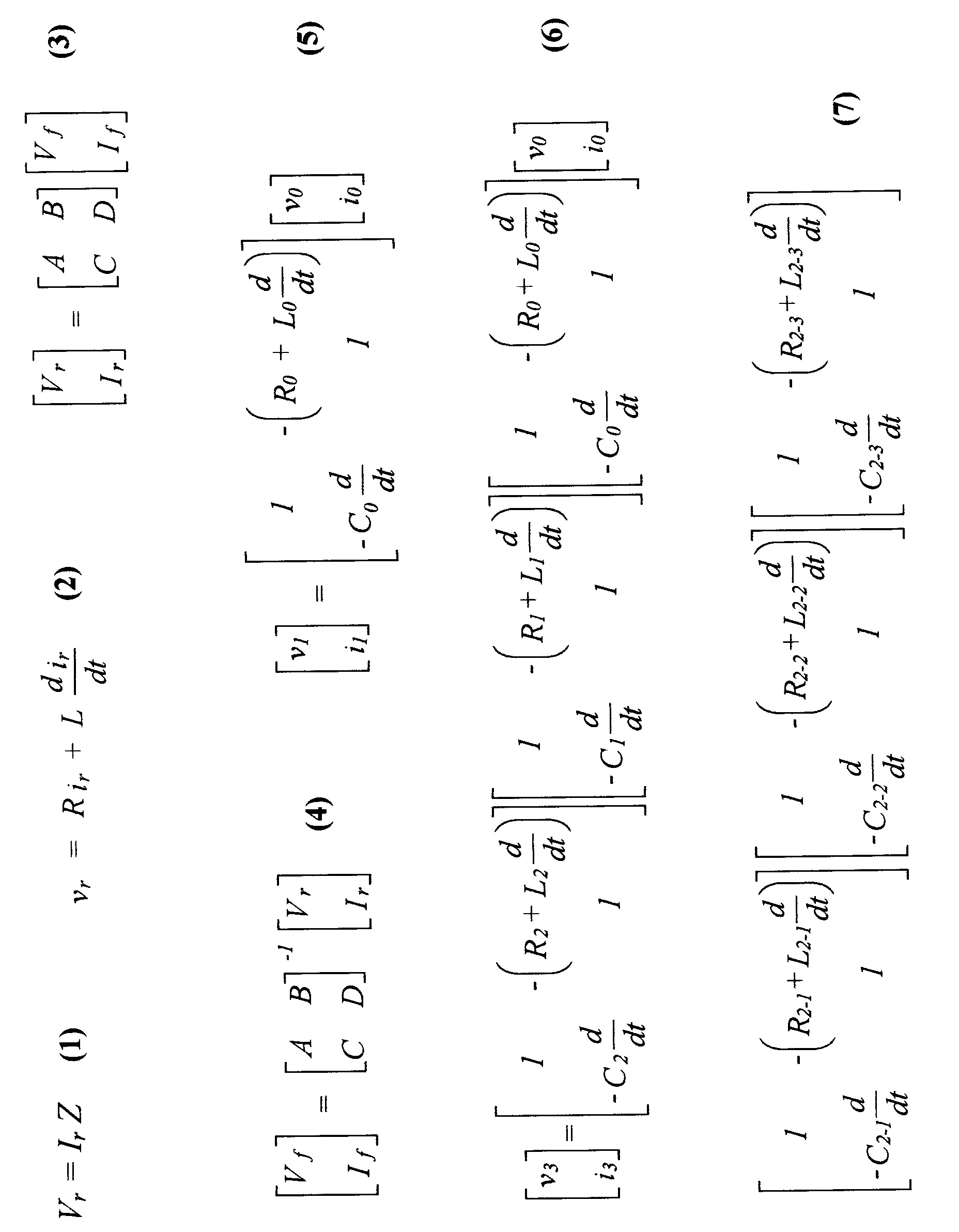
- FIG. 1 shows this scenario, in which a line 10 is considered to have a lumped impedance Z , consisting of an inductive reactance X L associated with an inductive component L , and a resistance R L and is monitored in terms of voltage V r and current I r at one end of the line. The other end of the line may be connected to a load which may be another AC power connection.
- equation (2) rather than the phase equation (1) removes the need for the relay input signals ⁇ r and i r to be at a specified frequency.
- equation (2) could be equally valid when applied to a 50Hz or 60Hz system, so that R and L could in principle be solved over a range of discrete time-signal frequencies of the relay inputs ⁇ r and i r .
- Equation (2) The value of shunt capacitance present in overhead lines is sufficiently low to be neglected at power-system frequency so that equation (2) can be used to determine the values of R and L .
- the presence of capacitance causes high-frequency travelling waves to be generated when a fault occurs and these can cause errors in the calculation of R and L . It is therefore necessary to remove the travelling-wave frequencies from the signals ⁇ r and i r before calculating R and L using equation (2). Since these frequencies are relatively high with respect to the power-system frequency, they can be removed by short-window digital filters without causing the relay operating time to be extended beyond one power-frequency cycle.
- relay equipment for an electrical power line characterised by fault-detection means comprising:
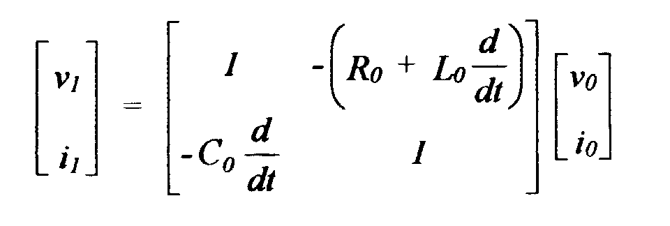
- the calculating means may calculate said intermediate-point voltage and current values using a value of a derivative of said second signal with respect to time, and preferably employing the matrix relationship: where ⁇ 1 , i 1 are said voltage and current at said intermediate point, ⁇ 0 , i 0 are said voltage and current at said first end of the line, R 0 and L 0 are said series parameters of the line and C 0 is a shunt parameter of the line.
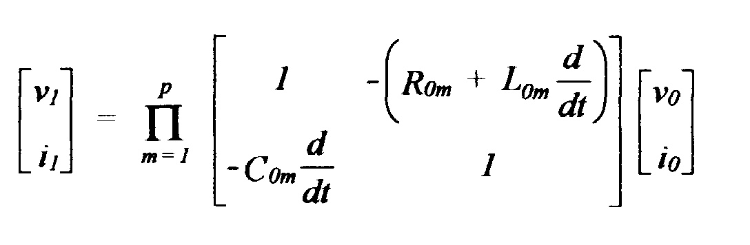
- the calculating means may be arranged to model said line as a plurality p of line-portions in series having respective series and shunt parameters, said matrix relationship being:
- Corresponding parameters of said line-portions may have substantially the same value.
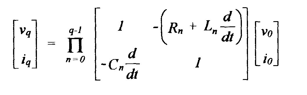
- the line may be composed of a plurality q of sections in series having respective series and shunt parameters, each of said plurality q of sections being composed of a plurality p of line-portions in series having respective series and shunt parameters, said matrix relationship being:
- At least the shunt parameters of said sections may not all be of substantially the same value.
- the sections may correspond to respective distinct forms of line including at least one overhead line section and at least one cable section.
- Each of said line or line-portions is preferably modelled by said calculating means as a ⁇ -network, though a ⁇ -network may also be employed.
- the fault-location determining means may comprise means for detecting whether said voltage at said intermediate point is zero, positive or negative relative to a reference quantity, a zero result indicating that there is a fault at said intermediate point, a positive result indicating that there is a fault between said point and one end of said line and a negative result indicating that there is a fault between said point and the other end of said line.
- the reference quantity may be the current associated with said intermediate point.
- the calculating means may comprise means for calculating from said calculated voltage and current values a value of a complex impedance between said first end and said intermediate point, and said fault-location determining means may comprise means for evaluating a sign of said complex impedance.
- a negative result may indicate that there is a fault between said intermediate point and said first end of said line and a positive result indicate that there is a fault between said intermediate point and said second end of said line.
- the intermediate point will usually lie approximately 80% of the way along said line from said first end of the line.
- the signal-deriving means may be adapted to derive said first and second signals both before and after the occurrence of a fault on said line
- said calculating means may be adapted to calculate from said pre-fault and post-fault first and second signals and from said parameters and from a value of a source impedance of said second end of said line a change in a value of voltage and current associated with said intermediate point and to calculate from said change a value of a complex impedance existing between said intermediate point and a reference point
- said fault-location determining means may be adapted to determine a sign of an imaginary part of said complex impedance and to infer from said sign a position of said fault relative to said intermediate point.
- a method of determining if a fault on a power line lies within a particular zone of said line comprises the steps of:
- the inference of said fault position may follow the rule that a negative sign indicates a fault between one of said ends and said intermediate point of said line, a positive sign indicates a fault between the other of said ends and said intermediate point of said line and a zero imaginary part indicates a fault at said intermediate point itself.
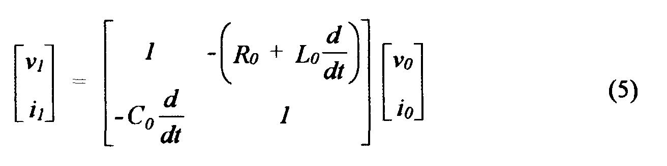
- the step of calculating the complex impedance may comprises a calculation of the voltage and current at said intermediate point using the equation: where ⁇ 0 , i 0 are the voltage and current at said first end of the line, ⁇ 1 , i 1 are the voltage and current at said intermediate point and R 0 , L 0 are series parameters and C 0 is a shunt parameter of said line.
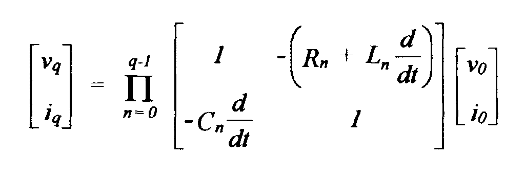
- the line may be divided into a plurality q of sections and said step of calculating the complex impedance may comprise a calculation of a voltage and current at said intermediate point using the equation: where ⁇ 0 , i 0 are the voltage and current at said first end of the line, ⁇ q , i q are the voltage and current at said intermediate point and R n , L n are series parameters and C n is a shunt parameter of respective said sections of the line.
- the line or each of said sections may be conceptually subdivided into p line-portions having respective line parameters, and said step of calculating the complex impedance may comprise a calculation of a voltage and current at said intermediate point using the equation:
- the intermediate point may lie approximately 80% of the way along the line from said first end thereof.
- the present invention takes into account the significant level of shunt capacitance which exists in cable circuits and employs the following relationship between the relaying voltage and current signals: where A , B , C and D represent the constants of the circuit up to the fault point and V f and I f represent the voltage between the faulted point on the line and a reference point, which is normally earth but may alternatively be another phase, and the current through the fault branch, respectively. Constants A , B , C and D would normally be hyperbolically derived for maximum accuracy.
- equation (3) can be recast as:
- this shows a "gamma” ( ⁇ ) circuit model of a section of line or cable to be monitored, but a “pi” ( ⁇ ) model could equally well be used.
- the voltage and current values, ⁇ 1 , i 1 at the right hand side of the section are calculated using a knowledge of the voltage and current values, ⁇ 0 , i 0 at the left hand side of the section, by the equation: where R 0 , C 0 and L 0 , are the resistance, capacitance and inductance values of the circuit section.
- the differential form of this equation allows the calculation to be made over a range of frequencies and not be restricted to solely the power-system frequency.
- the invention caters also for composite forms of line involving different parameters; an example is where a line takes the form of an overhead stretch of line in one location, continues as a cable section in another location and then becomes overhead again in a third location, and so on. This is shown in Figure 3. Under these conditions the calculation of the right hand-side voltage and current signals is achieved using: In order to achieve the correct bandwidth of operation and to retain accuracy by more closely approximating a hyperbolic circuit form, a preferred embodiment of the invention divides each circuit section into several cascaded matrices of the form used in equations (5) and (6).
- the first matrix on the right hand side of equation (6) can be expressed as (assuming the first overhead line section to be notionally divided into three subsections): This situation is illustrated in Figure 4, in which the second overhead line portion (line 2) is represented as being composed of three subsections in series, each having the parameter designations indicated.
- the voltage and current ⁇ 3 , i 3 correspond to a point on the line which is somewhat short of the right hand end of the line.
- the line is usually a section of line under the supervision of relaying equipment 100 at the end 22 of the line section.
- Relay 100 incorporates the fault-detection means of the present invention, implemented as microprocessor-based computing equipment programmed with the algorithms described herein. Further sections of line may be connected to the end 20 and these may be monitored by other relays. Thus, while the end of the relevant line section is shown as 20, the calculations performed in the relay 100 relate to a point 21 on the line. This is the "reach point" and is typically around 80% of the total line-section length.
- the reach-point voltage calculated by this method contains a considerably smaller proportion of travelling-wave frequencies than would be achieved by using a series R-L model.
- a small degree of filtering then allows phasor techniques to be used to determined the positive/negative nature of the reach-point voltage.
- a convenient reference phasor for this purpose is the reach-point current.
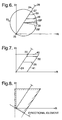
- the impedance Z (cf. Figure 1) to the fault is represented by a line 24 situated in the complex R-X plane and having its origin at a point 25 corresponding to the relaying point 22.
- the impedance equals zero at the relaying point, which is to be expected, and increases to a maximum at a point 26 corresponding to the end 20 of the line section, passing on its way though a value 27 corresponding to the reach-point value.
- Z will be somewhere along the line 24.
- the total impedance value will be displaced from the line 24, taking a value along the line 28, for example, for a fault midway between the relaying point and the reach point and having pure resistance and negligible infeed from the remote end of the line section.
- Other lines 29, 30 relate to similar faults at locations nearer the reach point.
- a suitable characteristic is a quadrilateral locus (see Figure 7) having as its essential elements a straight upper side 40 passing through the reach-point impedance value 27 and a right hand side 41 approximately parallel to the line 24.
- the relay For faults occurring close to the relay, the voltage input will be close to zero. Under these circumstances, the relay is unable to differentiate between faults in the protected zone, for which the relay must operate, and faults behind the relay location, where the relay is required to block. To overcome these difficulties the relay is provided with an estimate of the phase of the pre-fault voltage signal so that the direction of the fault can be ascertained; this is referred to as "polarisation".
- Polarisation can be achieved by using the voltages from phases not involved in the fault - so-called "sound (i.e., good) phase polarisation" - which are vectorially manipulated to give an approximation to the faulted-phase pre-fault voltage.
- memory polarisation where samples of the pre-fault voltage signal are stored in memory, can be used.
- the combination of measured and polarised signals is formed into a directional element as shown in the lower line of the quadrilateral of Figure 8.
- the signals employed for the directional element will be based on the signals at the relay point close to the busbar (i.e. measured signals) and not the reach-point values calculated by means of, for example, equation (8).
- any infeed at the remote end of the line section introduces phase shifts which can adversely affect the accuracy of the reach-point voltage and current calculations.
- the effect of a change in load can be to trip the relay (i.e. signal a fault) when a fault that has occurred lies in another zone, not the zone protected by the relay in question.
- a resistive fault lying outside the protected zone and involving no infeed is shown as line 50, whereas the same fault involving a transfer of power in one direction is shown as line 51 and in the other direction as line 52.
- line 52 passes through the quadrilateral characteristic 53 the relay in question will signal a fault in its zone.
- the present invention approaches this problem by incorporating in a preferred embodiment an improved reach-point directional element which will now be described.
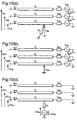
- Figure 10a represents a three-phase line under conditions of a fault between phase ⁇ and earth
- Figure 10b represents the same three-phase line as it appears just before the fault
- Figure 10c corresponds to the same line in its "superimposed" state, i.e. highlighting those quantities that have changed during the occurrence of the fault.
- the impedance in the fault path is shown as impedance Z f and the superposition circuit (Fig. 10(c)) is energised by an emf - V sfa which is the pre-fault voltage at the fault point.
- the fault point is assumed to be the reach point which is situated, as mentioned earlier, so that approximately 80% of the line impedance lies between the reach point and the relaying end and 20% lies between the reach point and the remote end of the line. Included with the 20% line impedance is the source impedance of the remote source which appears in Figure 10 as impedances Z sa , Z sb , Z sc .
- Figure 11 shows the superimposed state, the various superimposed voltage and current parameters having " ⁇ " designations.
- the reach point superimposed voltage and current values can be similarly calculated using the faulted and pre-fault values from the calculation of equation (6), (7) or (8), as appropriate.
- the unknown quantities in Figure 11 are Z f , Z sq and ⁇ I aa .
- Z s and Z m are the self and mutual impedances of the circuit section between the reach point and the remote end and including the assumed value of the remote source impedance. Since high-resistance earth faults are only likely where the reach point is on an overhead line rather than cable, the discrete time calculation of ⁇ I aa can be made by representing Z s , Z m as series resistance and inductance elements only, i.e. by using models of the form of equation (2) rather than equation (6) or (8).
- Z f is calculated by substitution of the value derived for ⁇ I aa from equation (14) into equation (13).
- equation (14) the quantities ⁇ I fb , ⁇ I fc , ⁇ V fa , ⁇ V fb and ⁇ V fc are all known from the reach-point calculation.
- equation (14) could be solved for Z s and Z m (the impedance to the right of the fault in Figure 11).
- the accuracy of the relaying process can be improved by using calculated values of Z s and Z m rather than the assumed values described earlier.
Landscapes
- Physics & Mathematics (AREA)
- General Physics & Mathematics (AREA)
- Locating Faults (AREA)
- Emergency Protection Circuit Devices (AREA)
- Communication Control (AREA)
- Investigating Or Analysing Materials By Optical Means (AREA)
- Testing Of Short-Circuits, Discontinuities, Leakage, Or Incorrect Line Connections (AREA)
- Application Of Or Painting With Fluid Materials (AREA)
- Power Steering Mechanism (AREA)
- Testing Or Measuring Of Semiconductors Or The Like (AREA)
Abstract
Description









| Fault Position | Re{Zf } | Im{Zf } | Remarks |
| In-zone | Pos. or Neg. | Negative | - |
| Reach point | Pos. or zero | Zero | Re{Zf } = true fault resistance |
| Out-of-zone | Positive | Positive | - |

Claims (23)
- Relay equipment (100, Fig. 3) for an electrical power line, characterised by fault-detection means comprising;a signal-deriving means for deriving first and second signals representative of a voltage and current, respectively, at a first end of said line;a calculating means for calculating from said first and second signals and from defined values of series and shunt parameters of said line a value of voltage and current associated with a point along said line intermediate said first end and a second end of said line, anda fault-location determining means for determining from said calculated voltage and current values whether a fault lies between said first end and said intermediate point.
- Relay equipment as claimed in Claim 1, wherein said calculating means calculates said intermediate-point voltage and current values using a value of a derivative of said second signal with respect to time.
- Relay equipment as claimed in Claim 2, wherein said calculating means performs said calculation on the basis of the matrix relationship:where ν1, i 1 are said voltage and current at said intermediate point, ν0, i 0 are said voltage and current at said first end of the line, R 0 and L 0 are said series parameters of the line and C 0 is a shunt parameter of the line.
- Relay equipment as claimed in Claim 3, wherein said calculating means is arranged to model said line as a plurality p of line-portions in series having respective series and shunt parameters, said matrix relationship being:
- Relay equipment as claimed in Claim 4, wherein corresponding parameters of said line-portions have substantially the same value.
- Relay equipment as claimed in Claim 4 or Claim 5, wherein said line is modelled as a plurality q of sections in series having respective series and shunt parameters, each of said plurality q of sections being composed of a plurality p of line-portions in series having respective series and shunt parameters, said matrix relationship being:

- Relay equipment as claimed in Claim 6, wherein at least the shunt parameters of said sections are not all of substantially the same value.
- Relay equipment as claimed in Claim 7, wherein said sections correspond to respective distinct forms of line including at least one overhead line section and at least one cable section.
- Relay equipment as claimed in any one of the preceding claims, wherein each said line or line-portion is modelled by said calculating means as a Γ-network.
- Relay equipment as claimed in any one of claims 1 to 9, wherein each said line or line-portion is modelled by said calculating means as a π-network.
- Relay equipment as claimed in any one of the preceding claims, wherein said fault-location determining means comprises means for detecting whether said voltage at said intermediate point is zero, positive or negative relative to a reference quantity, a zero result indicating that there is a fault at said intermediate point, a positive result indicating that there is a fault between said point and one end of said line and a negative result indicating that there is a fault between said point and the other end of said line.
- Relay equipment as claimed in Claim 11, wherein said reference quantity is the current associated with said intermediate point.
- Relay equipment as claimed in any one of Claims 1 to 10, wherein said calculating means comprises means for calculating from said calculated voltage and current values a value of a complex impedance between said first end and said intermediate point, and said fault-location determining means comprises means for evaluating a sign of said complex impedance.
- Relay equipment as claimed in Claim 13, wherein said calculating means is adapted to calculate said value of a complex impedance by means of the equation:
- Relay equipment as claimed in any one of Claims 11 to 14, wherein a negative result indicates that there is a fault between said intermediate point and said first end of said line and a positive result indicates that there is a fault between said intermediate point and said second end of said line.
- Relay equipment as claimed in any one of Claims 4 to 15, wherein said intermediate point lies approximately 80% of the way along said line from said first end of the line.
- Relay equipment as claimed in Claim 1, wherein said signal-deriving means is adapted to derive said first and second signals both before and after the occurrence of a fault on said line, said calculating means is adapted to calculate from said pre-fault and post-fault first and second signals and from said parameters and from a value of a source impedance of said second end of said line a change in a value of voltage and current associated with said intermediate point and to calculate from said change a value of a complex impedance existing between said intermediate point and a reference point, and wherein said fault-location determining means is adapted to determine a sign of an imaginary part of said complex impedance and to infer from said sign a position of said fault relative to said intermediate point.
- Method of determining if a fault on a power line lies within a particular zone of said line, characterised by the steps ofmeasuring a voltage and current at a first end of said line before and after the occurrence of a fault;calculating the complex impedance between a point on said line intermediate said first end and a second end of the line and a reference point, said complex fault impedance calculation utilizing the measured voltage and current values and values relating to parameters of the line and to a source impedance at said second end of the line;determining a sign of an imaginary part of said complex impedance, andinferring from said sign a position of said fault relative to said intermediate point on said line.
- Method as claimed in Claim 18, wherein said inference of said fault position follows the rule that a negative sign indicates a fault between one of said ends and said intermediate point of said line, a positive sign indicates a fault between the other of said ends and said intermediate point of said line and a zero imaginary part indicates a fault at said intermediate point itself.
- Method as claimed in Claim 18 or Claim 19, wherein said step of calculating the complex impedance comprises a calculation of the voltage and current at said intermediate point using the equation:where ν 0 , i0 are the voltage and current at said first end of the line, ν 1 , i1 are the voltage and current at said intermediate point and R0 , L0 are series parameters and C0 is a shunt parameter of said line.

- Method as claimed in Claim 18 or Claim 19, wherein said line is divided into a plurality q of sections and said step of calculating the complex impedance comprises a calculation of a voltage and current at said intermediate point using the equation:where ν 0 , i0 are the voltage and current at said first end of the line, ν q , iq are the voltage and current at said intermediate point and Rn , Ln are series parameters and Cn is a shunt parameter of respective said sections of the line.
- Method as claimed in Claim 20 or Claim 21, wherein said line or each of said sections is conceptually subdivided into p line-portions having respective line parameters, and said step of calculating the complex impedance comprises a calculation of a voltage and current at said intermediate point using the equation:

- Method as claimed in any one of Claims 18 to 22, wherein said intermediate point lies approximately 80% of the way along the line from said first end thereof.
Applications Claiming Priority (2)
| Application Number | Priority Date | Filing Date | Title |
|---|---|---|---|
| GB9900665 | 1999-01-13 | ||
| GB9900665A GB2345810B (en) | 1999-01-13 | 1999-01-13 | Fault-detection apparatus |
Publications (3)
| Publication Number | Publication Date |
|---|---|
| EP1020729A2 true EP1020729A2 (en) | 2000-07-19 |
| EP1020729A3 EP1020729A3 (en) | 2001-07-18 |
| EP1020729B1 EP1020729B1 (en) | 2007-09-05 |
Family
ID=10845893
Family Applications (1)
| Application Number | Title | Priority Date | Filing Date |
|---|---|---|---|
| EP00300150A Expired - Lifetime EP1020729B1 (en) | 1999-01-13 | 2000-01-11 | Fault detection for power lines |
Country Status (7)
| Country | Link |
|---|---|
| US (1) | US6601001B1 (en) |
| EP (1) | EP1020729B1 (en) |
| CN (1) | CN100360949C (en) |
| AT (1) | ATE372521T1 (en) |
| CA (1) | CA2295342C (en) |
| DE (1) | DE60036239T2 (en) |
| GB (1) | GB2345810B (en) |
Cited By (5)
| Publication number | Priority date | Publication date | Assignee | Title |
|---|---|---|---|---|
| EP1172660A3 (en) * | 2000-07-11 | 2005-12-21 | Abb Ab | Method and device for fault location in distribution networks |
| WO2016007217A1 (en) * | 2014-07-11 | 2016-01-14 | Abb Inc. | Decision support system for outage management and automated crew dispatch |
| WO2017072612A1 (en) * | 2015-10-30 | 2017-05-04 | Abb Schweiz Ag | Method and system for protection in a mixed line |
| WO2017177424A1 (en) | 2016-04-14 | 2017-10-19 | Abb Schweiz Ag | Method, system and apparatus for fault detection in line protection for power transmission system |
| US10359462B2 (en) | 2012-10-24 | 2019-07-23 | Wirescan As | Method and system for monitoring a condition of electrical cables |
Families Citing this family (43)
| Publication number | Priority date | Publication date | Assignee | Title |
|---|---|---|---|---|
| GB2375242A (en) * | 2001-05-03 | 2002-11-06 | Alstom | Protecting a section of an electrical power line |
| US6957117B2 (en) * | 2001-10-09 | 2005-10-18 | Public Service Electric And Gas Company | Portable protective air gap tool and method |
| US6988042B2 (en) * | 2003-11-25 | 2006-01-17 | Myongji University | Method for detecting line-to-line fault location in power network |
| US7142993B2 (en) * | 2004-10-13 | 2006-11-28 | Hewlett-Packard Development Company, L.P. | Determining a difference between a level of power to be supplied and an estimate |
| US7461925B2 (en) * | 2005-03-04 | 2008-12-09 | Hewlett-Packard Development Company, L.P. | Adjusting power |
| JP2006335954A (en) * | 2005-06-03 | 2006-12-14 | Sumika Bayer Urethane Kk | Blocked polyisocyanate composition and one-component coating composition |
| US7734430B2 (en) * | 2006-01-27 | 2010-06-08 | Hewlett-Packard Development Company, L.P. | Determining power |
| US8022709B2 (en) * | 2006-09-19 | 2011-09-20 | Abb Technology Ag | Method and apparatus for determining circular characteristic |
| CN101150248B (en) * | 2006-09-21 | 2010-05-26 | 田忠孝 | Method for adjusting over-deviation of failure voltage signal |
| US7793117B2 (en) * | 2006-10-12 | 2010-09-07 | Hewlett-Packard Development Company, L.P. | Method, apparatus and system for determining power supply to a load |
| CA2585820A1 (en) | 2007-04-18 | 2008-10-18 | Hydro-Quebec | Localizing faults on an electrical network using distributed voltage measurement |
| US8080769B2 (en) * | 2008-01-10 | 2011-12-20 | Hewlett-Packard Development Company, L.P. | Characterization of AC mains circuit parameters |
| US9257827B2 (en) | 2009-09-18 | 2016-02-09 | Schweitzer Engineering Laboratories, Inc. | Electrical power system phase and ground protection using an adaptive quadrilateral characteristic |
| CA2774517C (en) * | 2009-09-18 | 2015-01-27 | Schweitzer Engineering Laboratories, Inc. | Electrical power system phase and ground protection using an adaptive quadrilateral characteristic |
| WO2011156400A1 (en) * | 2010-06-07 | 2011-12-15 | Abb Research Ltd. | Systems and methods for characterizing fault-clearing devices |
| WO2012003888A1 (en) * | 2010-07-09 | 2012-01-12 | Siemens Aktiengesellschaft | Fast distance protection for energy supply networks |
| GB201120477D0 (en) * | 2011-11-28 | 2012-01-11 | Univ Nottingham | Fault location in power distribution systems |
| US9178350B2 (en) | 2011-11-30 | 2015-11-03 | General Electric Company | Electric distribution system protection |
| US9229036B2 (en) | 2012-01-03 | 2016-01-05 | Sentient Energy, Inc. | Energy harvest split core design elements for ease of installation, high performance, and long term reliability |
| US9182429B2 (en) | 2012-01-04 | 2015-11-10 | Sentient Energy, Inc. | Distribution line clamp force using DC bias on coil |
| CN104466788B (en) * | 2013-09-23 | 2018-05-08 | 国家电网公司 | The detection method and device of distribution overhead line |
| JP6161527B2 (en) * | 2013-12-10 | 2017-07-12 | 三菱電機株式会社 | Transmission line protection relay |
| CN104375057A (en) * | 2014-11-07 | 2015-02-25 | 国网上海市电力公司 | Automatic underground power line fault positioning and warning system |
| US9954354B2 (en) | 2015-01-06 | 2018-04-24 | Sentient Energy, Inc. | Methods and apparatus for mitigation of damage of power line assets from traveling electrical arcs |
| US9941684B2 (en) | 2015-05-12 | 2018-04-10 | Schweitzer Engineering Laboratories, Inc. | Phase and ground protection using tilt-limited adaptive quadrilateral characteristic |
| CN105044553B (en) * | 2015-06-25 | 2018-02-09 | 邵珠真 | Underground power cable fault location device |
| US9984818B2 (en) | 2015-12-04 | 2018-05-29 | Sentient Energy, Inc. | Current harvesting transformer with protection from high currents |
| US10634733B2 (en) | 2016-11-18 | 2020-04-28 | Sentient Energy, Inc. | Overhead power line sensor |
| NO20161993A1 (en) | 2016-12-15 | 2018-04-09 | Wirescan As | Method for measuring an impedance of an electric cable, a coupler arrangement and uses thereof |
| EP3571516B1 (en) * | 2017-01-22 | 2021-12-08 | Hitachi Energy Switzerland AG | Method and control system for fault direction detection |
| EP3639045B1 (en) * | 2017-06-15 | 2023-08-16 | Hitachi Energy Switzerland AG | Method, system and apparatus for fault detection |
| US10677834B2 (en) | 2018-09-14 | 2020-06-09 | Schweitzer Engineering Laboratories, Inc. | Distance protection of electric power delivery systems using time domain and frequency domain |
| US11041915B2 (en) | 2018-09-18 | 2021-06-22 | Sentient Technology Holdings, LLC | Disturbance detecting current sensor |
| US11476674B2 (en) | 2018-09-18 | 2022-10-18 | Sentient Technology Holdings, LLC | Systems and methods to maximize power from multiple power line energy harvesting devices |
| US10641815B2 (en) | 2018-09-27 | 2020-05-05 | Schweitzer Engineering Laboratories, Inc. | Secure distance protection of electric power delivery systems under transient conditions |
| US12050241B2 (en) | 2018-10-15 | 2024-07-30 | Sentient Technology Holdings, Llc. | Power line sensors with automatic phase identification |
| US11125832B2 (en) | 2018-12-13 | 2021-09-21 | Sentient Technology Holdings, LLC | Multi-phase simulation environment |
| US11609590B2 (en) | 2019-02-04 | 2023-03-21 | Sentient Technology Holdings, LLC | Power supply for electric utility underground equipment |
| US11735907B2 (en) | 2021-02-03 | 2023-08-22 | Schweitzer Engineering Laboratories, Inc. | Traveling wave overcurrent protection for electric power delivery systems |
| AU2023438724A1 (en) * | 2023-03-22 | 2025-09-11 | Hitachi Energy Ltd | A method of detecting a fault in a transmission line in an ac power transmission system |
| EP4618340A1 (en) * | 2024-03-11 | 2025-09-17 | Hitachi Energy Ltd | Distance protection for symmetrical three phase faults reach point voltage calculation |
| CN119757970B (en) * | 2024-12-26 | 2025-10-14 | 江苏征途电气科技有限公司 | A distribution network fault line selection perception measurement and control method and system |
| CN120490727B (en) * | 2025-06-10 | 2026-03-17 | 上海君世电气科技有限公司 | A method for monitoring partial discharge of power cable joints |
Family Cites Families (35)
| Publication number | Priority date | Publication date | Assignee | Title |
|---|---|---|---|---|
| GB1570491A (en) * | 1975-11-14 | 1980-07-02 | Gen Electric Co Ltd | Protective relay arrangements |
| CH613570A5 (en) * | 1976-03-25 | 1979-09-28 | Bbc Brown Boveri & Cie | |
| FR2418560A1 (en) * | 1978-02-23 | 1979-09-21 | Enertec | DETECTION OF THE POSITION OF A FAULT ON AN ELECTRICAL LINE |
| JPS5830554B2 (en) * | 1978-11-13 | 1983-06-29 | 東京電力株式会社 | Fault point location method for power line fault detection and power line protection |
| ZA827802B (en) * | 1981-10-27 | 1983-09-28 | Univ Nottingham | Determining location of faults in power transmission lines |
| US4617636A (en) * | 1982-03-03 | 1986-10-14 | National Research Development Corporation | Protection of electrical power supply systems |
| US4453191A (en) * | 1982-07-29 | 1984-06-05 | General Electric Company | Overvoltage directional relay |
| SE433405B (en) * | 1982-09-14 | 1984-05-21 | Asea Ab | PROCEDURE AND DEVICE FOR LOCATING A FAILURE ON A THREE-PHASE POWER CORD |
| US4528611A (en) * | 1983-02-22 | 1985-07-09 | Westinghouse Electric Corp. | Relay for pilot protection of electrical power lines |
| US4484245A (en) * | 1983-06-17 | 1984-11-20 | Westinghouse Electric Corp. | Directional comparison blocking protective relay system |
| JPS60180424A (en) * | 1984-02-28 | 1985-09-14 | 三菱電機株式会社 | Shorting distance relay |
| SE442920B (en) * | 1984-06-15 | 1986-02-03 | Asea Ab | METHOD AND DEVICE FOR DETECTION AND LOCATION OF A FAILURE ON A POWER CORD |
| US4766549A (en) * | 1984-11-30 | 1988-08-23 | Electric Power Research Institute, Inc. | Single-ended transmission line fault locator |
| US4706156A (en) * | 1985-04-17 | 1987-11-10 | The General Electric Company, P.L.C. | Protection apparatus |
| JPH0812222B2 (en) * | 1985-11-08 | 1996-02-07 | 株式会社東芝 | Digital fault locator |
| SE452534B (en) * | 1986-04-08 | 1987-11-30 | Asea Ab | PROCEDURE AND DEVICE FOR RESTRICTIONS AND DIRECT DISPLACEMENT IN CONNECTION WITH PROTECTION OF A POWER PIPE |
| US4725914A (en) * | 1986-12-16 | 1988-02-16 | Westinghouse Electric Corp. | Protective relay system for performing selective-pole trip determination |
| GB8727490D0 (en) * | 1987-11-24 | 1987-12-23 | Nat Res Dev | Detecting faults in transmission circuits |
| SE460804B (en) * | 1988-03-25 | 1989-11-20 | Asea Brown Boveri | PROCEDURE AND DEVICE FOR MISCELLANEOUS FAULTY ON A POWER CORD |
| GB2222688B (en) * | 1988-09-09 | 1992-12-23 | Gen Electric Co Plc | Equipment for and methods of locating the position of a fault on a power transmission line |
| EP0459522B1 (en) * | 1990-05-31 | 1995-12-20 | Nissin Electric Company, Limited | Fault location method for a parallel two-circuit transmission line with N terminals |
| SE466366B (en) * | 1990-06-29 | 1992-02-03 | Asea Brown Boveri | PROCEDURE AND DEVICE MAKES COMMON LOCATION IN THE MULTI-TERMINAL |
| JP3356484B2 (en) * | 1992-06-30 | 2002-12-16 | 株式会社東芝 | Accident point location device |
| US5455776A (en) * | 1993-09-08 | 1995-10-03 | Abb Power T & D Company Inc. | Automatic fault location system |
| GB2286088B (en) * | 1994-01-26 | 1997-09-24 | Gec Alsthom Ltd | A method of locating the position of a fault on a power transmission line |
| DE4402348C1 (en) * | 1994-01-27 | 1995-12-07 | Jungheinrich Ag | Circuit arrangement for a battery charger |
| CA2184091A1 (en) * | 1994-02-28 | 1995-09-08 | Damir Novosel | One-terminal data fault location system |
| GB2288930B (en) * | 1994-04-25 | 1998-01-21 | Gec Alsthom Ltd | Methods and apparatus for identifying faulted phases on an electric power transmission line |
| DE4441334C1 (en) * | 1994-11-08 | 1996-07-11 | Siemens Ag | Method for determining the location of a fault in a predetermined monitoring area of a multi-phase electrical power transmission line system |
| DE19605022A1 (en) * | 1996-01-31 | 1997-08-07 | Siemens Ag | Method for detecting an error on a line section to be monitored of an electrical transmission line according to the distance protection principle |
| US5839093A (en) * | 1996-12-31 | 1998-11-17 | Abb Transmit Oy | System for locating faults and estimating fault resistance in distribution networks with tapped loads |
| US5796258A (en) * | 1997-01-30 | 1998-08-18 | Abb Power T&D Company, Inc. | Adaptive quadrilateral characteristic distance relay |
| US5773980A (en) * | 1997-01-30 | 1998-06-30 | Abb Power T&D Company, Inc. | One-terminal fault location system that corrects for fault resistance effects |
| US5838525A (en) * | 1997-04-15 | 1998-11-17 | Abb Power T&D Company, Inc. | High speed single-pole trip logic for use in protective relaying |
| CN1195775A (en) * | 1997-12-23 | 1998-10-14 | 浙江大学 | Method and device for distinguishing transmission line fault direction |
-
1999
- 1999-01-13 GB GB9900665A patent/GB2345810B/en not_active Expired - Fee Related
-
2000
- 2000-01-11 DE DE60036239T patent/DE60036239T2/en not_active Expired - Lifetime
- 2000-01-11 AT AT00300150T patent/ATE372521T1/en not_active IP Right Cessation
- 2000-01-11 EP EP00300150A patent/EP1020729B1/en not_active Expired - Lifetime
- 2000-01-12 CA CA002295342A patent/CA2295342C/en not_active Expired - Fee Related
- 2000-01-13 CN CNB001009788A patent/CN100360949C/en not_active Expired - Fee Related
- 2000-01-13 US US09/482,835 patent/US6601001B1/en not_active Expired - Fee Related
Cited By (9)
| Publication number | Priority date | Publication date | Assignee | Title |
|---|---|---|---|---|
| EP1172660A3 (en) * | 2000-07-11 | 2005-12-21 | Abb Ab | Method and device for fault location in distribution networks |
| US10359462B2 (en) | 2012-10-24 | 2019-07-23 | Wirescan As | Method and system for monitoring a condition of electrical cables |
| WO2016007217A1 (en) * | 2014-07-11 | 2016-01-14 | Abb Inc. | Decision support system for outage management and automated crew dispatch |
| US9874593B2 (en) | 2014-07-11 | 2018-01-23 | Abb Inc. | Decision support system for outage management and automated crew dispatch |
| WO2017072612A1 (en) * | 2015-10-30 | 2017-05-04 | Abb Schweiz Ag | Method and system for protection in a mixed line |
| US11114843B2 (en) | 2015-10-30 | 2021-09-07 | Abb Power Grids Switzerland Ag | Method and system for protection in a mixed line |
| WO2017177424A1 (en) | 2016-04-14 | 2017-10-19 | Abb Schweiz Ag | Method, system and apparatus for fault detection in line protection for power transmission system |
| EP3443368A4 (en) * | 2016-04-14 | 2020-01-22 | ABB Schweiz AG | LINE PROTECTION FAULT DETECTION METHOD, SYSTEM AND APPARATUS FOR ELECTRICAL TRANSMISSION SYSTEM |
| US11652347B2 (en) | 2016-04-14 | 2023-05-16 | Hitachi Energy Switzerland Ltd | Method, system and apparatus for fault detection in line protection for power transmission system |
Also Published As
| Publication number | Publication date |
|---|---|
| ATE372521T1 (en) | 2007-09-15 |
| DE60036239D1 (en) | 2007-10-18 |
| GB2345810B (en) | 2003-07-23 |
| DE60036239T2 (en) | 2008-06-05 |
| GB9900665D0 (en) | 1999-03-03 |
| CN1261672A (en) | 2000-08-02 |
| CA2295342A1 (en) | 2000-07-13 |
| US6601001B1 (en) | 2003-07-29 |
| EP1020729B1 (en) | 2007-09-05 |
| GB2345810A (en) | 2000-07-19 |
| CN100360949C (en) | 2008-01-09 |
| EP1020729A3 (en) | 2001-07-18 |
| CA2295342C (en) | 2009-12-22 |
Similar Documents
| Publication | Publication Date | Title |
|---|---|---|
| EP1020729B1 (en) | Fault detection for power lines | |
| US11022655B2 (en) | Method and control system for faulted phase detection | |
| US7180300B2 (en) | System and method of locating ground fault in electrical power distribution system | |
| EP1992954B1 (en) | Method for determining location of phase-to-earth fault | |
| RU2491563C2 (en) | Technique and device for detection of phase-to-ground fault | |
| JP6711844B2 (en) | Fault position detection and distance protection device and related method | |
| EP2686691B1 (en) | A method for detecting earth faults | |
| US7514933B2 (en) | System and method for determining location of phase-to-earth fault | |
| WO1995024014A2 (en) | One-terminal data fault location system | |
| US6584417B1 (en) | Method and directional element for fault direction determination in a capacitance-compensated line | |
| EP0876620B1 (en) | Method of detecting and locating a high-resistance earth fault in an electric power network | |
| Chowdhury et al. | Power system fault detection and state estimation using Kalman filter with hypothesis testing | |
| WO1998029752A1 (en) | System for locating faults and estimating fault resistance in distribution networks with tapped loads | |
| US9461458B2 (en) | Method of distance protection of parallel transmission line | |
| CN102484365A (en) | Methods of Fault Phase Selection and Fault Type Determination | |
| WO1998029752A9 (en) | System for locating faults and estimating fault resistance in distribution networks with tapped loads | |
| EP3639337B1 (en) | Method and control system for fault direction detection | |
| US4261038A (en) | Protection of electrical power supply systems | |
| US5764044A (en) | Process for producing time dependent waveforms of positive and negative symmetrical sequence components of a power system's voltages or currents | |
| EP3799240B1 (en) | Systems and methods to improve distance protection in transmission lines | |
| US5325061A (en) | Computationally-efficient distance relay for power transmission lines | |
| EP2070170B1 (en) | Method and apparatus for determining circular characteristic | |
| RU2073876C1 (en) | Method for detecting ground fault in power transmission line | |
| EP4412018A1 (en) | A method of detecting a fault in a protected line in a power transmission system | |
| AU705490B2 (en) | Apparatus and process for producing time dependent waveforms of a power systems currents |
Legal Events
| Date | Code | Title | Description |
|---|---|---|---|
| PUAI | Public reference made under article 153(3) epc to a published international application that has entered the european phase |
Free format text: ORIGINAL CODE: 0009012 |
|
| AK | Designated contracting states |
Kind code of ref document: A2 Designated state(s): AT BE CH CY DE DK ES FI FR GB GR IE IT LI LU MC NL PT SE |
|
| AX | Request for extension of the european patent |
Free format text: AL;LT;LV;MK;RO;SI |
|
| PUAL | Search report despatched |
Free format text: ORIGINAL CODE: 0009013 |
|
| AK | Designated contracting states |
Kind code of ref document: A3 Designated state(s): AT BE CH CY DE DK ES FI FR GB GR IE IT LI LU MC NL PT SE |
|
| AX | Request for extension of the european patent |
Free format text: AL;LT;LV;MK;RO;SI |
|
| 17P | Request for examination filed |
Effective date: 20010716 |
|
| AKX | Designation fees paid |
Free format text: AT BE CH CY DE DK ES FI FR GB GR IE IT LI LU MC NL PT SE |
|
| RAP1 | Party data changed (applicant data changed or rights of an application transferred) |
Owner name: ALSTOM UK |
|
| RAP1 | Party data changed (applicant data changed or rights of an application transferred) |
Owner name: AREVA T&D UK LTD. |
|
| 17Q | First examination report despatched |
Effective date: 20060912 |
|
| GRAP | Despatch of communication of intention to grant a patent |
Free format text: ORIGINAL CODE: EPIDOSNIGR1 |
|
| GRAS | Grant fee paid |
Free format text: ORIGINAL CODE: EPIDOSNIGR3 |
|
| GRAA | (expected) grant |
Free format text: ORIGINAL CODE: 0009210 |
|
| AK | Designated contracting states |
Kind code of ref document: B1 Designated state(s): AT BE CH CY DE DK ES FI FR GB GR IE IT LI LU MC NL PT SE |
|
| REG | Reference to a national code |
Ref country code: GB Ref legal event code: FG4D |
|
| REG | Reference to a national code |
Ref country code: CH Ref legal event code: EP |
|
| REF | Corresponds to: |
Ref document number: 60036239 Country of ref document: DE Date of ref document: 20071018 Kind code of ref document: P |
|
| REG | Reference to a national code |
Ref country code: IE Ref legal event code: FG4D |
|
| REG | Reference to a national code |
Ref country code: SE Ref legal event code: TRGR |
|
| REG | Reference to a national code |
Ref country code: CH Ref legal event code: NV Representative=s name: BOVARD AG PATENTANWAELTE |
|
| PG25 | Lapsed in a contracting state [announced via postgrant information from national office to epo] |
Ref country code: FI Free format text: LAPSE BECAUSE OF FAILURE TO SUBMIT A TRANSLATION OF THE DESCRIPTION OR TO PAY THE FEE WITHIN THE PRESCRIBED TIME-LIMIT Effective date: 20070905 Ref country code: ES Free format text: LAPSE BECAUSE OF FAILURE TO SUBMIT A TRANSLATION OF THE DESCRIPTION OR TO PAY THE FEE WITHIN THE PRESCRIBED TIME-LIMIT Effective date: 20071216 |
|
| PG25 | Lapsed in a contracting state [announced via postgrant information from national office to epo] |
Ref country code: AT Free format text: LAPSE BECAUSE OF FAILURE TO SUBMIT A TRANSLATION OF THE DESCRIPTION OR TO PAY THE FEE WITHIN THE PRESCRIBED TIME-LIMIT Effective date: 20070905 |
|
| NLV1 | Nl: lapsed or annulled due to failure to fulfill the requirements of art. 29p and 29m of the patents act | ||
| PG25 | Lapsed in a contracting state [announced via postgrant information from national office to epo] |
Ref country code: BE Free format text: LAPSE BECAUSE OF FAILURE TO SUBMIT A TRANSLATION OF THE DESCRIPTION OR TO PAY THE FEE WITHIN THE PRESCRIBED TIME-LIMIT Effective date: 20070905 |
|
| PG25 | Lapsed in a contracting state [announced via postgrant information from national office to epo] |
Ref country code: NL Free format text: LAPSE BECAUSE OF FAILURE TO SUBMIT A TRANSLATION OF THE DESCRIPTION OR TO PAY THE FEE WITHIN THE PRESCRIBED TIME-LIMIT Effective date: 20070905 Ref country code: GR Free format text: LAPSE BECAUSE OF FAILURE TO SUBMIT A TRANSLATION OF THE DESCRIPTION OR TO PAY THE FEE WITHIN THE PRESCRIBED TIME-LIMIT Effective date: 20071206 |
|
| EN | Fr: translation not filed | ||
| ET | Fr: translation filed | ||
| REG | Reference to a national code |
Ref country code: FR Ref legal event code: EERR Free format text: CORRECTION DE BOPI 08/18 - BREVETS EUROPEENS DONT LA TRADUCTION N A PAS ETE REMISE A L INPI. IL Y A LIEU DE SUPPRIMER : LA MENTION DE LA NON-REMISE. LA REMISE DE LA TRADUCTION EST PUBLIEE DANS LE PRESENT BOPI. |
|
| PG25 | Lapsed in a contracting state [announced via postgrant information from national office to epo] |
Ref country code: PT Free format text: LAPSE BECAUSE OF FAILURE TO SUBMIT A TRANSLATION OF THE DESCRIPTION OR TO PAY THE FEE WITHIN THE PRESCRIBED TIME-LIMIT Effective date: 20080206 |
|
| PLBE | No opposition filed within time limit |
Free format text: ORIGINAL CODE: 0009261 |
|
| STAA | Information on the status of an ep patent application or granted ep patent |
Free format text: STATUS: NO OPPOSITION FILED WITHIN TIME LIMIT |
|
| PG25 | Lapsed in a contracting state [announced via postgrant information from national office to epo] |
Ref country code: DK Free format text: LAPSE BECAUSE OF FAILURE TO SUBMIT A TRANSLATION OF THE DESCRIPTION OR TO PAY THE FEE WITHIN THE PRESCRIBED TIME-LIMIT Effective date: 20070905 |
|
| 26N | No opposition filed |
Effective date: 20080606 |
|
| PG25 | Lapsed in a contracting state [announced via postgrant information from national office to epo] |
Ref country code: MC Free format text: LAPSE BECAUSE OF NON-PAYMENT OF DUE FEES Effective date: 20080131 |
|
| GBPC | Gb: european patent ceased through non-payment of renewal fee |
Effective date: 20080111 |
|
| PG25 | Lapsed in a contracting state [announced via postgrant information from national office to epo] |
Ref country code: GB Free format text: LAPSE BECAUSE OF NON-PAYMENT OF DUE FEES Effective date: 20080111 |
|
| PG25 | Lapsed in a contracting state [announced via postgrant information from national office to epo] |
Ref country code: IE Free format text: LAPSE BECAUSE OF NON-PAYMENT OF DUE FEES Effective date: 20080111 |
|
| PG25 | Lapsed in a contracting state [announced via postgrant information from national office to epo] |
Ref country code: CY Free format text: LAPSE BECAUSE OF FAILURE TO SUBMIT A TRANSLATION OF THE DESCRIPTION OR TO PAY THE FEE WITHIN THE PRESCRIBED TIME-LIMIT Effective date: 20070905 |
|
| PG25 | Lapsed in a contracting state [announced via postgrant information from national office to epo] |
Ref country code: LU Free format text: LAPSE BECAUSE OF NON-PAYMENT OF DUE FEES Effective date: 20080111 |
|
| PG25 | Lapsed in a contracting state [announced via postgrant information from national office to epo] |
Ref country code: IT Free format text: LAPSE BECAUSE OF NON-PAYMENT OF DUE FEES Effective date: 20080131 |
|
| REG | Reference to a national code |
Ref country code: CH Ref legal event code: PFA Owner name: AREVA T&D UK LTD. Free format text: AREVA T&D UK LTD.#ST LEONARDS AVENUE#STAFFORD ST 17 4LX (GB) -TRANSFER TO- AREVA T&D UK LTD.#ST LEONARDS AVENUE#STAFFORD ST 17 4LX (GB) |
|
| PGFP | Annual fee paid to national office [announced via postgrant information from national office to epo] |
Ref country code: CH Payment date: 20110124 Year of fee payment: 12 Ref country code: DE Payment date: 20110121 Year of fee payment: 12 Ref country code: SE Payment date: 20110113 Year of fee payment: 12 Ref country code: FR Payment date: 20110202 Year of fee payment: 12 |
|
| REG | Reference to a national code |
Ref country code: CH Ref legal event code: PL |
|
| REG | Reference to a national code |
Ref country code: SE Ref legal event code: EUG |
|
| REG | Reference to a national code |
Ref country code: FR Ref legal event code: ST Effective date: 20120928 |
|
| PG25 | Lapsed in a contracting state [announced via postgrant information from national office to epo] |
Ref country code: SE Free format text: LAPSE BECAUSE OF NON-PAYMENT OF DUE FEES Effective date: 20120112 Ref country code: LI Free format text: LAPSE BECAUSE OF NON-PAYMENT OF DUE FEES Effective date: 20120131 Ref country code: CH Free format text: LAPSE BECAUSE OF NON-PAYMENT OF DUE FEES Effective date: 20120131 Ref country code: DE Free format text: LAPSE BECAUSE OF NON-PAYMENT OF DUE FEES Effective date: 20120801 |
|
| REG | Reference to a national code |
Ref country code: DE Ref legal event code: R119 Ref document number: 60036239 Country of ref document: DE Effective date: 20120801 |
|
| PG25 | Lapsed in a contracting state [announced via postgrant information from national office to epo] |
Ref country code: FR Free format text: LAPSE BECAUSE OF NON-PAYMENT OF DUE FEES Effective date: 20120131 |