EP1020661A2 - Method and apparatus for polishing external-tooth gears - Google Patents
Method and apparatus for polishing external-tooth gears Download PDFInfo
- Publication number
- EP1020661A2 EP1020661A2 EP00100747A EP00100747A EP1020661A2 EP 1020661 A2 EP1020661 A2 EP 1020661A2 EP 00100747 A EP00100747 A EP 00100747A EP 00100747 A EP00100747 A EP 00100747A EP 1020661 A2 EP1020661 A2 EP 1020661A2
- Authority
- EP
- European Patent Office
- Prior art keywords
- tooth
- external
- tooth gear
- polishing
- gear
- Prior art date
- Legal status (The legal status is an assumption and is not a legal conclusion. Google has not performed a legal analysis and makes no representation as to the accuracy of the status listed.)
- Granted
Links
Images


Classifications
-
- B—PERFORMING OPERATIONS; TRANSPORTING
- B24—GRINDING; POLISHING
- B24B—MACHINES, DEVICES, OR PROCESSES FOR GRINDING OR POLISHING; DRESSING OR CONDITIONING OF ABRADING SURFACES; FEEDING OF GRINDING, POLISHING, OR LAPPING AGENTS
- B24B3/00—Sharpening cutting edges, e.g. of tools; Accessories therefor, e.g. for holding the tools
- B24B3/34—Sharpening cutting edges, e.g. of tools; Accessories therefor, e.g. for holding the tools of turning or planing tools or tool bits, e.g. gear cutters
-
- B—PERFORMING OPERATIONS; TRANSPORTING
- B24—GRINDING; POLISHING
- B24B—MACHINES, DEVICES, OR PROCESSES FOR GRINDING OR POLISHING; DRESSING OR CONDITIONING OF ABRADING SURFACES; FEEDING OF GRINDING, POLISHING, OR LAPPING AGENTS
- B24B1/00—Processes of grinding or polishing; Use of auxiliary equipment in connection with such processes
- B24B1/04—Processes of grinding or polishing; Use of auxiliary equipment in connection with such processes subjecting the grinding or polishing tools, the abrading or polishing medium or work to vibration, e.g. grinding with ultrasonic frequency
-
- B—PERFORMING OPERATIONS; TRANSPORTING
- B24—GRINDING; POLISHING
- B24B—MACHINES, DEVICES, OR PROCESSES FOR GRINDING OR POLISHING; DRESSING OR CONDITIONING OF ABRADING SURFACES; FEEDING OF GRINDING, POLISHING, OR LAPPING AGENTS
- B24B21/00—Machines or devices using grinding or polishing belts; Accessories therefor
- B24B21/004—Machines or devices using grinding or polishing belts; Accessories therefor using abrasive rolled strips
-
- B—PERFORMING OPERATIONS; TRANSPORTING
- B24—GRINDING; POLISHING
- B24B—MACHINES, DEVICES, OR PROCESSES FOR GRINDING OR POLISHING; DRESSING OR CONDITIONING OF ABRADING SURFACES; FEEDING OF GRINDING, POLISHING, OR LAPPING AGENTS
- B24B35/00—Machines or devices designed for superfinishing surfaces on work, i.e. by means of abrading blocks reciprocating with high frequency
-
- F—MECHANICAL ENGINEERING; LIGHTING; HEATING; WEAPONS; BLASTING
- F16—ENGINEERING ELEMENTS AND UNITS; GENERAL MEASURES FOR PRODUCING AND MAINTAINING EFFECTIVE FUNCTIONING OF MACHINES OR INSTALLATIONS; THERMAL INSULATION IN GENERAL
- F16H—GEARING
- F16H55/00—Elements with teeth or friction surfaces for conveying motion; Worms, pulleys or sheaves for gearing mechanisms
- F16H55/02—Toothed members; Worms
- F16H55/06—Use of materials; Use of treatments of toothed members or worms to affect their intrinsic material properties
Definitions
- the present invention relates to a method and an apparatus for polishing an external-tooth gear which is inscribed and meshed with an internal-tooth gear inside the internal-tooth gear, and in particular to a method and an apparatus suitable for polishing tooth surfaces of the external-tooth gear used for gearing such that the center of the internal-tooth gear lies inside the periphery of external-tooth gear.
- an inscribed meshing planetary gear construction comprising: a first shaft; an eccentric body which is rotated by the rotation of the first shaft; a plurality of external-tooth gears which are attached eccentrically rotatably to the eccentric bodies through bearings; an internal-tooth gear with which the external-tooth gears are inscribed and meshed through internal teeth composed of outer pins; and an second shaft which is connected to the external-tooth gears through inner pins for extracting only the rotational component of the external-tooth gears.
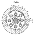
- FIGs. 7 and 8 An example of the prior art of this construction is illustrated in Figs. 7 and 8. This example applies above-described construction to a "speed reduction gear" by using the first shaft as an input shaft and using the second shaft as an output shaft and at the same time by fixing the internal-tooth gear.
- Eccentric bodies 3a and 3b are fitted to the input shaft 1 with a predetermined phase difference (180 degree in this case).
- the eccentric bodies 3a and 3b (center: O2) are decentered respectively relative to the input shaft 1 (center: O1) by an eccentricity e.
- Two external-tooth gears 5a and 5b are attached to each of these eccentric bodies 3a and 3b in plural rows through bearings 4a and 4b.
- a plurality of inner-roller holes 6a and 6b are provided in the external-tooth gears 5a and 5b. In these inner-roller holes 6a and 6b, inner pins 7 and inner rollers 8 are fitted.
- a main object of providing two external-tooth gears is to increase a transmission capacity, maintain a strength and retain a rotation balance.
- External teeth 9 such as trochoid teeth or arcuate teeth are provided on the outer circumferences of the external-tooth gears 5a and 5b.
- the external teeth 9 are inscribed and meshed with the internal-tooth gear 20 fixed to a casing 12.
- the internal-tooth gear 20 consists of a pin retaining ring 10 and outer pins 11.
- the pin retaining ring 10 has a plurality of semicircular pin retaining holes 13 disposed along the inner circumference of the inner-tooth gear in an axial direction thereof.
- the outer pins 11 are fitted to the pin retaining holes 13 so as to easily rotate with a play and which form arcuate tooth profiles at the parts where the outer pins project from the pin retaining holes 13.
- the inner pins 7 passing through the external-tooth gears 5a and 5b are fixed securely to or fitted into a flange part around the output shaft 2.
- the difference between their numbers of teeth is 1.
- the external-tooth gears 5a and 5b are displaced (rotates) by one tooth relative to the internal-tooth gear 20 fixed to the casing 12 every time the input shaft 1 is rotated once. This means that one revolution of the input shaft 1 is decelerated to a revolution of -1/N of the external-tooth gear 5a and 5b.
- this inscribed meshing planetary gear construction is applied to various speed reduction gears or increasing gears.
- the first shaft is used as an input shaft and the second shaft is used as an output shaft, with the internal-tooth gear fixed.
- a reduction gear can also be constructed by using the first shaft as an input shaft and the internal-tooth gear as an output shaft, as well as by fixing the second shaft.
- a "speed increase gear” can also be constructed by reversing these input shaft and output shaft in such a construction.
- this mechanism in order to downsize an inscribed meshing planetary gear mechanism of this type and provide it with a high load carrying capacity, this mechanism must be manufactured so that, among components having meshing parts and sliding parts, the internal-tooth gear 20 has a high strength property, and the external-tooth gears 5a and 5b, outer pins 11, inner rollers 8, inner pins 7, bearings 4a and 4b, and eccentric bodies 3a and 3b have a high strength property as well as a high hardness. Therefore, above-described components are usually made of metallic materials having such properties.
- Japanese Patent Application No.Sho 60-271649 Japanese Patent Publication No.Hei 2-36825; Japanese Patent No. 16237157 proposes contact surfaces which are formed with irregular surfaces in the tooth trace direction of grinding marks on tooth profiles and in the direction perpendicular to the tooth trace direction of grinding marks (the tooth profile direction), and which are covered with conversion coatings of less thicknesses than the heights of the irregularities. These are aimed to provide construction of contact surfaces such as to allow the clearances between contact surfaces in transmission mechanism to be narrowed and at the same time allow lubricating oil to be retained for a long period of time, and to provide a method for producing such contact surfaces.
- the present invention resolves the above-described problems by a method for polishing external-tooth gear, wherein teeth of the external-tooth gear and a film polishing member are made to slide relative to each other in the tooth profile direction (the direction in which teeth are aligned, i.e., the circumferential direction of external-tooth gear), while the film polishing member is pressed against tooth surfaces of the external-tooth gear by backing up with a pressing member.
- the external-tooth gear of oscillatory inscribed meshing construction of this type provides smooth tooth profiles such as arcuate tooth profiles or trochoid tooth profiles.
- smooth tooth profiles such as arcuate tooth profiles or trochoid tooth profiles.
- Reduction of surface roughness also allows the realization of fluid lubrication between contact surfaces. This, in turn, enables the gap between teeth to be narrowed without a threat of seizure, and further enables wobbling noises as well as angular backlash to be reduced.
- the press polishing in the tooth profile direction using the film polishing member may be executed after teeth of the external-tooth gear have been polished in the tooth trace direction with a formed grindstone. This permits a more efficient polishing.
- teeth of the external-tooth gear may be vibrated relative to the film polishing member in the tooth trace direction. This leads to a further improvement in surface roughness.
- the pressing surface of pressing member may be formed into a convex curved surface having a smaller curvature than that of the concave curved surface of a tooth profile of the external-tooth gear, and the film polishing member may be pressed against tooth surfaces of the external-tooth gear through that convex curved surface. This allows an efficient polishing of tooth surfaces, especially those of valley parts of teeth.
- teeth of the external-tooth gear to be polished may be made to slide relative to the film polishing member in the tooth profile direction.
- a tooth profile of the external-tooth gear of this type is, including tooth bottom part, formed of smooth curve such as an arcuate tooth profile or a trochoid tooth profile, rotation of the teeth permits the tooth surfaces along tooth profile curves to be polished with reliability in the tooth profile direction.
- polyester films coated with a particulate abrasives such as aluminum oxide, silicon carbide and diamond.
- an apparatus for polishing external-tooth gear comprising: a film polishing member for polishing tooth surfaces of the external-tooth gear; a pressing mechanism which has a pressing member capable of advancing and retreating relative to the center of axis of the external-tooth gear in the radial direction, and which presses the film polishing member against tooth surfaces of the gear with a predetermined pressure through the pressing member; and a polishing drive mechanism for making slide teeth of the gear relative to the film polishing member in the tooth profile direction.
- a pneumatic cylinder mechanism As means for pressing the film polishing member against tooth surfaces with a predetermined pressure, for example, a pneumatic cylinder mechanism may be used.
- a film advance unit for advancing (pulling) long lengths of film polishing member in the longitudinal direction, and a gear rotation unit for supporting and rotating an external-tooth gear as work may be utilized.
- a minute reciprocative rotational drive can be easily achieved in both the directions of tooth trace and tooth profile, and thereby a polishing effect by reciprocating sliding can be more enhanced.
- an oscillation mechanism for oscillating teeth of the external-tooth gear relative to the film polishing member in the tooth trace direction can enhance a polishing effect even further.
- FIG. 1 shows a schematic block diagram of a polishing apparatus for executing the polishing method in accordance with the present invention
- FIG. 2 shows the critical portion in FIG. 1 in an enlarged form.
- work to be polished is an external-tooth gear W of the same kind as external-tooth gears 5a and 5b of the inscribed meshing planetary gear mechanism shown in FIGS. 7 and 8.
- This external-tooth gear W has trochoid tooth profiles on the periphery thereof, and is supported on a horizontal driving shaft 101.
- the driving shaft 101 is adapted to be reciprocatively rotated in the tooth profile direction (the circumferential direction of the external-tooth gear W: see FIG. 2) while supporting the external-tooth gear W, and simultaneously to be minutely vibrated (oscillated) in the tooth trace direction (the axial direction of the external-tooth gear W: see FIG. 2).
- referential numeral 102 denotes a rotational driving unit (polishing drive mechanism) for rotating the driving shaft
- 103 denotes an oscillation unit for minutely vibrating the driving shaft.
- a film polishing member 110 for polishing tooth surfaces of the external-tooth gear W is laid on the periphery of the external-tooth gear W supported on the driving shaft 101 so that the film polishing member 110 covers approximately a half of the periphery of the external-tooth gear W.
- the film polishing member 110 is, as its cross section is shown in FIG. 3, one composed of a polyester film 110a of which surface is coated with abrasive particles (fine particulate abrasives) 110d such as aluminum oxide, silicon carbide and diamond using thermosetting adhesives 110b and 110c.
- abrasive particles 110d such as aluminum oxide, silicon carbide and diamond using thermosetting adhesives 110b and 110c.
- the side on which parts of the abrasive particles 110d are exposed is the polishing side.
- shoes 120 as pressing members in the pressing mechanism for pressing the film polishing member 110 against tooth surfaces of the external-tooth gear W.
- the shoes 120 are supported on arms 131 of a constant-pressure pressing unit 130 incorporating a pneumatic cylinder mechanism and the like, and serve as a backing up member for pressing the film polishing member 110 against tooth surfaces of the external-tooth gear W with a constant pressure P.
- each of these shoes 120 is formed into a convex curved surface having a smaller curvature than that of the concave curved surface of a trochoid tooth profile (a curved surface having a curvature R to such an extent as to follow tooth surfaces of the external-tooth gear W as the gear is rotated), so that the convex surface is capable of polishing valley parts of teeth reliably and efficiently by pressing the film polishing member 110 against tooth surfaces.
- a polishing control unit for controlling the rotational driving unit 102 and the oscillation unit 103, a film advance unit for advancing (pulling) the film polishing member 110 and a control unit for the constant-pressure pressing unit 130 (any of these not shown).
- the process of tooth finish consists of two steps; a first step is to perform a grinding operation by means of a grindstone, and a second step is to carry out a polishing operation using the above-described polishing apparatus.
- teeth is ground by rotating a grindstone 201 formed into a tooth profile while keeping the grindstone in intimate contact with the tooth profile of the external-tooth gear W, and simultaneously by moving the external-tooth gear W in the tooth trace direction (the direction perpendicular to the plane of the figure).
- This step is a basis for the tooth finish process, and the pitch accuracy and tooth profile accuracy are secured in this step. At this time, roughness and waviness remains in the tooth profile direction of tooth surfaces, as illustrated in FIG. 5.
- the film polishing member 110 is placed so as to surround the outer periphery of the external-tooth gear W, and then the film polishing member 110 is pressed against tooth surfaces of the external-tooth gear W with a constant pressure P using shoes 120 by actuating the constant-pressure pressing unit 130.
- the external-tooth gear W is rotated intermittently or continuously in the clockwise and counter-clockwise directions (the external-tooth gear and the film polishing member are made to slide relative to each other). Consequently, tooth surfaces are polished in the tooth profile direction by the film polishing member 110. At this time, provision of a minute vibration (oscillation) for the external-tooth gear W in the trace direction promotes the polishing effect on tooth surfaces.
- FIG. 6 shows data after the second step.
- the second step eliminates the waviness and roughness in the tooth profile direction, which were present in the first step.
- the film polishing member 110 is advanced (pulled) by a predetermined amount at the stage where a polishing has been carried out for a predetermined time period, at the stage where the external-tooth gear W has been polished by a predetermined angle, or at the stage where a predetermined number of teeth have been polished, so as to polish the gear with new surfaces of the film polishing member.
- the present polishing apparatus may be constructed, for example, so that the film polishing member 110 is advanced (pulled) while the external-tooth gear W is oscillating only in the tooth trace direction.
- the invention relates to a method for polishing a tooth gear (W), characterized in that teeth of said gear (W) and a polishing member (110) are made to slide relative to each other.
Landscapes
- Engineering & Computer Science (AREA)
- Mechanical Engineering (AREA)
- General Engineering & Computer Science (AREA)
- Physics & Mathematics (AREA)
- Electromagnetism (AREA)
- Thermal Sciences (AREA)
- Retarders (AREA)
- Finish Polishing, Edge Sharpening, And Grinding By Specific Grinding Devices (AREA)
- Gear Processing (AREA)
- Gears, Cams (AREA)
Abstract
Description
Claims (8)
- A method for polishing an external-tooth gear (W), characterized in that teeth of said external-tooth gear (W) and a film polishing member (110) are made to slide relative to each other in the tooth profile direction while said film polishing member (110) is pressed against tooth surfaces of said external-tooth gear (W) by backing up with a pressing member (120), so that said tooth surfaces is press-polished.
- The method for polishing an external-tooth gear (W) according to claim 1, wherein the press-polishing in the tooth profile direction using said film polishing member (110) is executed after said external-tooth gear (W) has been polished in the tooth trace direction with a formed grindstone (201).
- The method for polishing an external-tooth gear (W) according to claim 1 or claim 2, wherein the teeth of said external-tooth gear (W) are further oscillated relative to said film polishing member (110) in the tooth trace direction, when the press-polishing in the tooth profile direction using said film polishing member (110) is executed.
- The method for polishing an external-tooth gear (W) according to any one of claims 1 to 3, wherein a pressing surface of said pressing member (120) is formed into a convex curved surface having a smaller curvature than that of a concave curved surface of a tooth profile of said external-tooth gear (W), and wherein said film polishing member (110) is pressed against the tooth surfaces of said external-tooth gear (W) through said convex curved surface.
- The method for polishing an external-tooth gear (W) according to any one of claims 1 to 4, wherein said film polishing member (110) is made capable of advancing and retreating in a radial direction relative to a center of axis of the external-tooth gear (W) and wherein said external-tooth gear (W) is rotated about the center of axis thereof, so that teeth of the external-tooth gear (W) to be polished is made to slide relative to the film polishing member (110) in the tooth profile direction.
- An apparatus for polishing an external-tooth gear (W), comprising:a film polishing member (110) for polishing tooth surfaces of said external-tooth gear (W);a pressing mechanism (120,131,130) for pressing said film polishing member (110) against the tooth surfaces with a predetermined pressure, said pressing mechanism (120,131,130) having a pressing member (120) capable of advancing and retreating relative to a center of axis of said external-tooth gear (W) in a radial direction; anda polishing driving mechanism (101,102,103) for making slide teeth of said external-tooth gear (W) and said film polishing member (110) relative to each other in a tooth profile direction.
- The apparatus for polishing an external-tooth gear (W) according to claim 6, further comprising:an oscillation mechanism (103) for making teeth of said external-tooth gear (W) oscillate relative to said film polishing member (110)in a tooth trace direction.
- A method for polishing a tooth gear (W), characterized in that teeth of said gear (W) and a polishing member (110) are made to slide relative to each other.
Applications Claiming Priority (2)
| Application Number | Priority Date | Filing Date | Title |
|---|---|---|---|
| JP802199 | 1999-01-14 | ||
| JP00802199A JP4172865B2 (en) | 1999-01-14 | 1999-01-14 | External gear polishing method and polishing apparatus |
Publications (3)
| Publication Number | Publication Date |
|---|---|
| EP1020661A2 true EP1020661A2 (en) | 2000-07-19 |
| EP1020661A3 EP1020661A3 (en) | 2002-01-30 |
| EP1020661B1 EP1020661B1 (en) | 2005-03-30 |
Family
ID=11681694
Family Applications (1)
| Application Number | Title | Priority Date | Filing Date |
|---|---|---|---|
| EP00100747A Expired - Lifetime EP1020661B1 (en) | 1999-01-14 | 2000-01-14 | Method and apparatus for polishing external-tooth gears |
Country Status (7)
| Country | Link |
|---|---|
| US (1) | US6174223B1 (en) |
| EP (1) | EP1020661B1 (en) |
| JP (1) | JP4172865B2 (en) |
| KR (1) | KR100415734B1 (en) |
| CN (1) | CN1144640C (en) |
| DE (1) | DE60018998T2 (en) |
| TW (1) | TW449512B (en) |
Cited By (1)
| Publication number | Priority date | Publication date | Assignee | Title |
|---|---|---|---|---|
| CN112404605A (en) * | 2020-11-27 | 2021-02-26 | 刘高敬 | Gear grinding device for machining |
Families Citing this family (18)
| Publication number | Priority date | Publication date | Assignee | Title |
|---|---|---|---|---|
| AU763202B2 (en) * | 1997-12-05 | 2003-07-17 | Universal Entertainment Corporation | Game machine informing prize mode information in a series of flow of game |
| EP1447171B1 (en) | 2003-02-12 | 2006-07-12 | Nissan Motor Co., Ltd. | Surface finishing apparatus and method |
| CN100411790C (en) * | 2005-06-22 | 2008-08-20 | 全宏齿轮工业股份有限公司 | Gear break-in device |
| DE102007036000B4 (en) * | 2007-07-30 | 2015-12-31 | Jahnel-Kestermann Getriebewerke Gmbh & Co. Kg | Tooth flank polishing tool |
| US20100242283A1 (en) * | 2009-03-30 | 2010-09-30 | Gm Global Technology Operations, Inc. | Method for finishing a gear surface |
| EP2647459B1 (en) * | 2012-04-02 | 2017-03-01 | Klingelnberg AG | Device and method for processing bevelled wheels using an eccentrically moved grinding tool |
| US9029805B2 (en) * | 2013-02-25 | 2015-05-12 | American Axle & Manufacturing, Inc. | Method for inspecting contact between mating gears |
| CN103240467B (en) * | 2013-05-27 | 2015-05-06 | 四川省内江庆隆机床有限公司 | Gear aligning device for lapping machine and gear aligning method |
| CN105196010B (en) * | 2015-09-01 | 2018-03-27 | 河北科技师范学院 | Roller oscillating tooth gear reductor centre wheel work flank profil method for processing surface and device |
| CN106112134B (en) * | 2016-08-23 | 2017-12-22 | 无锡市东赫金属制品有限公司 | A kind of automobile gear sander with fine adjustment function |
| CN108381397B (en) * | 2018-03-03 | 2021-03-02 | 北京工业大学 | Contact pressure detection system for abrasive belt polishing machine |
| CN108869638A (en) * | 2018-06-01 | 2018-11-23 | 安徽尚豪齿轮科技有限公司 | A kind of height applied to knife sharpener, which subtracts, compares gear set |
| CN108655930A (en) * | 2018-06-11 | 2018-10-16 | 江苏省溧水弹簧厂(普通合伙) | A kind of leaf spring surface processing device |
| CN111761444B (en) * | 2020-07-02 | 2021-08-17 | 浙江三欢齿轮有限公司 | Grinding machine for gear machining |
| CN113275667B (en) * | 2021-05-19 | 2022-07-29 | 湖北博英精工科技股份有限公司 | Gear grinding device |
| CN115194618A (en) * | 2022-09-19 | 2022-10-18 | 江苏珀然股份有限公司 | Hub grinding device |
| CN117381074B (en) * | 2023-10-26 | 2025-11-11 | 珠海飞马传动机械有限公司 | Improved cycloidal gear paired gear grinding tool |
| CN117943626A (en) * | 2024-02-02 | 2024-04-30 | 华南理工大学 | A high-efficiency cycloid gear grinding and polishing device |
Family Cites Families (6)
| Publication number | Priority date | Publication date | Assignee | Title |
|---|---|---|---|---|
| DE2556170C3 (en) * | 1975-12-13 | 1980-02-07 | Jahnel Getriebebau Gmbh, 4630 Bochum | Grinding or polishing device for a gear |
| CH667029A5 (en) * | 1985-07-01 | 1988-09-15 | Reishauer Ag | METHOD FOR CONTROLLING TOOL INPUT WHEN MACHINING STARTS ON A GEAR MACHINE. |
| JPS62132068A (en) * | 1985-12-04 | 1987-06-15 | Sumitomo Heavy Ind Ltd | Contact face of transmission mechanism and its manufacture |
| US4920703A (en) * | 1986-06-04 | 1990-05-01 | Koganei Seiki Seisakusho | Method and apparatus for finishing a tooth surface of a gear |
| JPH0624682B2 (en) * | 1987-12-26 | 1994-04-06 | 株式会社日進製作所 | Super finishing machine using wrapping film |
| JP3073179B2 (en) * | 1997-07-10 | 2000-08-07 | 株式会社松田精機 | Super finishing device using film abrasive |
-
1999
- 1999-01-14 JP JP00802199A patent/JP4172865B2/en not_active Expired - Lifetime
-
2000
- 2000-01-11 US US09/481,569 patent/US6174223B1/en not_active Expired - Lifetime
- 2000-01-13 KR KR10-2000-0001481A patent/KR100415734B1/en not_active Expired - Fee Related
- 2000-01-13 TW TW089100494A patent/TW449512B/en not_active IP Right Cessation
- 2000-01-14 EP EP00100747A patent/EP1020661B1/en not_active Expired - Lifetime
- 2000-01-14 DE DE60018998T patent/DE60018998T2/en not_active Expired - Fee Related
- 2000-01-14 CN CNB001045083A patent/CN1144640C/en not_active Expired - Lifetime
Cited By (2)
| Publication number | Priority date | Publication date | Assignee | Title |
|---|---|---|---|---|
| CN112404605A (en) * | 2020-11-27 | 2021-02-26 | 刘高敬 | Gear grinding device for machining |
| CN112404605B (en) * | 2020-11-27 | 2022-03-22 | 临沂元泰机械有限公司 | Gear grinding device for machining |
Also Published As
| Publication number | Publication date |
|---|---|
| EP1020661B1 (en) | 2005-03-30 |
| US6174223B1 (en) | 2001-01-16 |
| KR100415734B1 (en) | 2004-01-31 |
| EP1020661A3 (en) | 2002-01-30 |
| DE60018998T2 (en) | 2006-02-09 |
| TW449512B (en) | 2001-08-11 |
| JP4172865B2 (en) | 2008-10-29 |
| KR20000053476A (en) | 2000-08-25 |
| JP2000205377A (en) | 2000-07-25 |
| DE60018998D1 (en) | 2005-05-04 |
| CN1267578A (en) | 2000-09-27 |
| CN1144640C (en) | 2004-04-07 |
Similar Documents
| Publication | Publication Date | Title |
|---|---|---|
| US6174223B1 (en) | Method and apparatus for polishing external-tooth gears | |
| US20030070297A1 (en) | Method for fabricating external-tooth gears | |
| US6170156B1 (en) | Gear tooth smoothing and shaping process | |
| KR100389247B1 (en) | Traction drive rotary assembly and process for producing rolling element thereof | |
| US5683323A (en) | Ball-rolling type torque transmission device | |
| CN1157274C (en) | Method for manufacturing pin retaining ring for internal gear, internally meshing planetary gear structure, and hydraulic motor-pump | |
| JPH0446244A (en) | Conical rolling equal tooth thickness bevel gear device and machining method thereof | |
| JP3067794B2 (en) | Oil pump | |
| EP0981420B1 (en) | Polishing head for plate materials in granite, hard stone or ceramic with abrasive segments having continuous oscillating tangential motion | |
| JP3557355B2 (en) | Method of manufacturing pin retaining ring for internal gear of internal meshing gear mechanism | |
| EP1332823A1 (en) | Gear, and method and device for finishing tooth face of gear | |
| KR20070021684A (en) | External Gear and Processing Method of Planetary Gear Reducer with Cycloidal Teeth | |
| JPH0451676B2 (en) | ||
| JP4278816B2 (en) | Reduction method of angular backlash of swinging intermeshing planetary gear transmission | |
| JP2785079B2 (en) | Inner meshing planetary gear device and method of forming outer pin hole contact surface for contacting outer pin of the inner meshing planetary gear device | |
| JP2010032025A (en) | Planetary roller screw device | |
| JPH0236825B2 (en) | ||
| JP4149603B2 (en) | External gear polishing method and polishing apparatus | |
| JPH11315908A (en) | Gear pair and Coriolis motion gear device | |
| JP2001289180A (en) | Gear pump or gear motor | |
| JP2000130357A (en) | Manufacture of roller holding ring for hydraulic pressure motor pump | |
| KR100225137B1 (en) | Manufacturing method of inner roller and outer roller of inner gear planetary gear structure | |
| JP2025165894A (en) | gearbox | |
| US6524087B1 (en) | Hydrostatic planetary rotation machine having an orbiting rotary valve | |
| JPH033075B2 (en) |
Legal Events
| Date | Code | Title | Description |
|---|---|---|---|
| PUAI | Public reference made under article 153(3) epc to a published international application that has entered the european phase |
Free format text: ORIGINAL CODE: 0009012 |
|
| AK | Designated contracting states |
Kind code of ref document: A2 Designated state(s): DE FR GB IT Kind code of ref document: A2 Designated state(s): AT BE CH CY DE DK ES FI FR GB GR IE IT LI LU MC NL PT SE |
|
| AX | Request for extension of the european patent |
Free format text: AL;LT;LV;MK;RO;SI |
|
| PUAL | Search report despatched |
Free format text: ORIGINAL CODE: 0009013 |
|
| AK | Designated contracting states |
Kind code of ref document: A3 Designated state(s): AT BE CH CY DE DK ES FI FR GB GR IE IT LI LU MC NL PT SE |
|
| AX | Request for extension of the european patent |
Free format text: AL;LT;LV;MK;RO;SI |
|
| RIC1 | Information provided on ipc code assigned before grant |
Free format text: 7F 16H 55/02 A, 7F 16H 55/06 B, 7B 24B 21/16 B |
|
| 17P | Request for examination filed |
Effective date: 20020705 |
|
| AKX | Designation fees paid |
Free format text: DE FR GB IT |
|
| 17Q | First examination report despatched |
Effective date: 20030414 |
|
| GRAP | Despatch of communication of intention to grant a patent |
Free format text: ORIGINAL CODE: EPIDOSNIGR1 |
|
| GRAS | Grant fee paid |
Free format text: ORIGINAL CODE: EPIDOSNIGR3 |
|
| GRAA | (expected) grant |
Free format text: ORIGINAL CODE: 0009210 |
|
| AK | Designated contracting states |
Kind code of ref document: B1 Designated state(s): DE FR GB IT |
|
| REG | Reference to a national code |
Ref country code: GB Ref legal event code: FG4D |
|
| REF | Corresponds to: |
Ref document number: 60018998 Country of ref document: DE Date of ref document: 20050504 Kind code of ref document: P |
|
| REG | Reference to a national code |
Ref country code: IE Ref legal event code: FG4D |
|
| PLBE | No opposition filed within time limit |
Free format text: ORIGINAL CODE: 0009261 |
|
| STAA | Information on the status of an ep patent application or granted ep patent |
Free format text: STATUS: NO OPPOSITION FILED WITHIN TIME LIMIT |
|
| 26N | No opposition filed |
Effective date: 20060102 |
|
| ET | Fr: translation filed | ||
| PGFP | Annual fee paid to national office [announced via postgrant information from national office to epo] |
Ref country code: GB Payment date: 20070110 Year of fee payment: 8 |
|
| PGFP | Annual fee paid to national office [announced via postgrant information from national office to epo] |
Ref country code: IT Payment date: 20070529 Year of fee payment: 8 |
|
| PGFP | Annual fee paid to national office [announced via postgrant information from national office to epo] |
Ref country code: FR Payment date: 20070109 Year of fee payment: 8 |
|
| GBPC | Gb: european patent ceased through non-payment of renewal fee |
Effective date: 20080114 |
|
| REG | Reference to a national code |
Ref country code: FR Ref legal event code: ST Effective date: 20081029 |
|
| PG25 | Lapsed in a contracting state [announced via postgrant information from national office to epo] |
Ref country code: GB Free format text: LAPSE BECAUSE OF NON-PAYMENT OF DUE FEES Effective date: 20080114 |
|
| PG25 | Lapsed in a contracting state [announced via postgrant information from national office to epo] |
Ref country code: FR Free format text: LAPSE BECAUSE OF NON-PAYMENT OF DUE FEES Effective date: 20080131 |
|
| PGFP | Annual fee paid to national office [announced via postgrant information from national office to epo] |
Ref country code: DE Payment date: 20090108 Year of fee payment: 10 |
|
| PG25 | Lapsed in a contracting state [announced via postgrant information from national office to epo] |
Ref country code: IT Free format text: LAPSE BECAUSE OF NON-PAYMENT OF DUE FEES Effective date: 20080114 |
|
| PG25 | Lapsed in a contracting state [announced via postgrant information from national office to epo] |
Ref country code: DE Free format text: LAPSE BECAUSE OF NON-PAYMENT OF DUE FEES Effective date: 20100803 |