EP1020624A2 - Exhaust gas temperature estimation - Google Patents
Exhaust gas temperature estimation Download PDFInfo
- Publication number
- EP1020624A2 EP1020624A2 EP00300247A EP00300247A EP1020624A2 EP 1020624 A2 EP1020624 A2 EP 1020624A2 EP 00300247 A EP00300247 A EP 00300247A EP 00300247 A EP00300247 A EP 00300247A EP 1020624 A2 EP1020624 A2 EP 1020624A2
- Authority
- EP
- European Patent Office
- Prior art keywords
- egr
- exhaust gas
- gas temperature
- temperature
- egr valve
- Prior art date
- Legal status (The legal status is an assumption and is not a legal conclusion. Google has not performed a legal analysis and makes no representation as to the accuracy of the status listed.)
- Granted
Links
- 238000002485 combustion reaction Methods 0.000 claims abstract description 13
- 239000002826 coolant Substances 0.000 claims description 8
- 238000000034 method Methods 0.000 claims 5
- 239000007789 gas Substances 0.000 description 51
- 239000003570 air Substances 0.000 description 12
- 230000006870 function Effects 0.000 description 5
- CURLTUGMZLYLDI-UHFFFAOYSA-N Carbon dioxide Chemical compound O=C=O CURLTUGMZLYLDI-UHFFFAOYSA-N 0.000 description 2
- 239000012080 ambient air Substances 0.000 description 2
- QVGXLLKOCUKJST-UHFFFAOYSA-N atomic oxygen Chemical compound [O] QVGXLLKOCUKJST-UHFFFAOYSA-N 0.000 description 2
- 239000000446 fuel Substances 0.000 description 2
- 239000000203 mixture Substances 0.000 description 2
- 229910052760 oxygen Inorganic materials 0.000 description 2
- 239000001301 oxygen Substances 0.000 description 2
- 229910002092 carbon dioxide Inorganic materials 0.000 description 1
- 239000001569 carbon dioxide Substances 0.000 description 1
- 238000011217 control strategy Methods 0.000 description 1
- 238000001816 cooling Methods 0.000 description 1
- 238000013500 data storage Methods 0.000 description 1
- 230000003247 decreasing effect Effects 0.000 description 1
- 238000010586 diagram Methods 0.000 description 1
- 230000000694 effects Effects 0.000 description 1
- 239000000126 substance Substances 0.000 description 1
- 238000011144 upstream manufacturing Methods 0.000 description 1
Images

Classifications
-
- F—MECHANICAL ENGINEERING; LIGHTING; HEATING; WEAPONS; BLASTING
- F02—COMBUSTION ENGINES; HOT-GAS OR COMBUSTION-PRODUCT ENGINE PLANTS
- F02D—CONTROLLING COMBUSTION ENGINES
- F02D41/00—Electrical control of supply of combustible mixture or its constituents
- F02D41/0025—Controlling engines characterised by use of non-liquid fuels, pluralities of fuels, or non-fuel substances added to the combustible mixtures
- F02D41/0047—Controlling exhaust gas recirculation [EGR]
- F02D41/0065—Specific aspects of external EGR control
- F02D41/0072—Estimating, calculating or determining the EGR rate, amount or flow
-
- F—MECHANICAL ENGINEERING; LIGHTING; HEATING; WEAPONS; BLASTING
- F02—COMBUSTION ENGINES; HOT-GAS OR COMBUSTION-PRODUCT ENGINE PLANTS
- F02D—CONTROLLING COMBUSTION ENGINES
- F02D41/00—Electrical control of supply of combustible mixture or its constituents
- F02D41/0025—Controlling engines characterised by use of non-liquid fuels, pluralities of fuels, or non-fuel substances added to the combustible mixtures
- F02D41/0047—Controlling exhaust gas recirculation [EGR]
- F02D41/0065—Specific aspects of external EGR control
- F02D2041/0067—Determining the EGR temperature
- F02D2041/007—Determining the EGR temperature by estimation
-
- Y—GENERAL TAGGING OF NEW TECHNOLOGICAL DEVELOPMENTS; GENERAL TAGGING OF CROSS-SECTIONAL TECHNOLOGIES SPANNING OVER SEVERAL SECTIONS OF THE IPC; TECHNICAL SUBJECTS COVERED BY FORMER USPC CROSS-REFERENCE ART COLLECTIONS [XRACs] AND DIGESTS
- Y02—TECHNOLOGIES OR APPLICATIONS FOR MITIGATION OR ADAPTATION AGAINST CLIMATE CHANGE
- Y02T—CLIMATE CHANGE MITIGATION TECHNOLOGIES RELATED TO TRANSPORTATION
- Y02T10/00—Road transport of goods or passengers
- Y02T10/10—Internal combustion engine [ICE] based vehicles
- Y02T10/40—Engine management systems
Definitions
- the present invention relates to an exhaust gas recirculation system of an internal combustion engine.
- Internal combustion engines typically include an exhaust gas recirculation (EGR) system to recirculate a controlled portion of the engine exhaust gas into an engine intake manifold in order to provide a reduction in NO x emissions.
- EGR exhaust gas recirculation
- a control mechanism including an EGR valve is provided to vary the EGR rate according to one or more sensed conditions, such as engine coolant temperature, air charge entering the intake manifold, and engine speed.
- a stepper motor driven EGR valve has been employed in an exhaust gas recirculation system wherein stepper motor steps are calculated primarily as a function of engine speed and air charge. Control of the EGR stepper motor without accounting for the temperature of the exhaust gas flowing through the EGR system can produce errors in control of the EGR valve and resulting EGR mass flow rate.
- An object of the present invention is to provide an estimated EGR exhaust gas temperature to improve control of an EGR valve to provide a desired EGR mass flow rate.
- An embodiment of the present invention estimates EGR gas temperature at an EGR valve of an EGR system of an internal combustion engine by estimating exhaust gas temperature at a location in the engine exhaust manifold, estimating the exhaust gas temperature drop between the exhaust manifold location and the EGR valve orifice, and estimating a time constant that models dynamics of the exhaust gas temperature at the EGR valve versus EGR mass flow rate.
- the exhaust gas temperature at the EGR valve is estimated by adjusting the estimated exhaust gas temperature at the exhaust manifold location by the estimated exhaust gas temperature drop and the estimated time constant.
- FIG. 1 illustrates an internal combustion engine 105 whose operation is controlled by Electronic Engine Controller (EEC) 100, which includes a central processing unit 41 (CPU), a read-only memory (ROM) 42 for storing control programs, a random-access memory (RAM) 43 for temporary data storage, a keep-alive memory (KAM) 44 for storing learned values, conventional data bus and I/O ports 40 for transmitting and receiving signals to and from the engine.
- EEC Electronic Engine Controller
- CPU central processing unit 41
- ROM read-only memory
- RAM random-access memory
- KAM keep-alive memory
- EEC 100 receives signals from a plurality of sensors generally designated 106, including but not limited to, an engine speed sensor and engine circulating coolant temperature sensor designated schematically at 106a and 106b, which transmit signals containing information indicative of the rotational speed of the engine, the temperature of the engine coolant circulating in the engine, and other engine operating parameters to EEC 100 over respective signal lines designated generally as 145.
- sensors 106 are conventional and may take one of several known forms.
- EEC 100 receives signals 145 along with other signals such as signals 144 and 146 described below and generates control signals for controlling spark timing, the rate of fuel delivered to engine combustion chambers and other operational functions of the engine.
- engine 105 draws an intake air mixture into intake manifold 120 past a manifold absolute pressure (MAP) sensor 102 which transmits a signal indicative of MAP to EEC 100.
- MAP manifold absolute pressure
- a throttle position sensor 159 senses the angular position of throttle lever 175 and transmits a throttle position signal 144 indicative of the angular position of throttle lever 175 to EEC 100.
- Dotted line 110 indicates the flow of the intake charge air entering the intake manifold 120.
- An air temperature sensor 176 can be used to detect the temperature of the air charge on the fresh air side of the throttle plate entering intake manifold 120 and transmits a representative signal 177 to EEC 100.
- Ambient air temperature sensor 179 is disposed outside the engine air cleaner assembly (not shown) and senses ambient temperature and transmits a representative signal 181 to EEC 100.
- Manifold charge temperature sensor 183 is disposed in manifold 120 and senses manifold charge temperature, which can include air and EGR gas, between the engine throttle plate and engine intake valves and transmits representative signal 185 to EEC 100.
- Sensors 102, 159, 176, 179 and 183 are each conventional.
- Exhaust gas generated from the combustion of an air/fuel mixture within the engine combustion chambers travels from the combustion chambers through exhaust manifold 130 as indicated by dotted lines 111.
- a heated exhaust gas oxygen sensor (HEGO) 104 detects the oxygen content within the exhaust gas and transmits a representative signal 146 to EEC 100.
- HEGO heated exhaust gas oxygen sensor
- the engine includes an exhaust gas recirculation (EGR) system for transporting a controlled portion of exhaust gas generated by the engine from an exhaust manifold 130 into the intake manifold 120 via an EGR conduit or passage 125.
- EGR exhaust gas recirculation
- the amount of exhaust gas which is recirculated from the exhaust manifold to the intake manifold is controlled by a conventional DC stepper motor driven EGR valve 150 having a stepper motor 151 that receives signals 142 from EEC 100 to axially move the valve 150 in incremental steps in a manner to control its position relative to a flow orifice 155 communicating to intake manifold 120.
- Control of the EGR system is effected as a portion of a background routine executed by the EEC 100 substantially continuously during engine operation in the absence of higher priority interrupt routines.
- Enablement of the stepper motor driven EGR valve 150 occurs only under engine operation conditions where all of the associated hardware is operating properly.
- the EGR valve is enabled when the engine is not in a closed throttle mode, not commanded off by torque control strategy and not in a crank mode, and the sensors 102, 106a, 106b, 159, 176, 179, 183 are operating in acceptable manner and generate respective signals.
- the EGR system In enabling the EGR system, if the engine coolant temperature at engine start is less than a calibratable minimum value (e.g. less than 180 degrees F), then the EGR system is ramped on over a calibratable time period, EGRMPT. (e.g. 30 seconds) via a multiplier TESGRE. If the engine coolant temperature at engine start is greater than the calibratable minimum value, then the EGR system is immediately enabled. Implementation of the EGR routine by EEC 100 in this manner is described and shown in Figure 2 of U.S. Patent 5 515 833 of common assignee herewith, the teachings of which are incorporated herein to this end.
- the exhaust gas temperature at EGR valve 150 (e.g. at the hot upstream side of EGR valve orifice 155) is estimated by estimating an exhaust gas temperature at engine exhaust manifold 130 in accordance with U.S. Patent 5,414,994, the teachings of which are incorporated herein by reference.
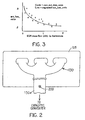
- exhaust gas temperature is estimated as described below at a flange 130a of the engine exhaust manifold 130 where a temperature sensor 200, Figure 2, is shown positioned for engine dynamometer testing only; i.e. sensor 200 is not used in actual practice of the invention where EGR gas temperature at the EGR valve 150 is estimated as described below.
- the estimated exhaust gas temperature at the flange 130a is adjusted by estimated drop, ext_ls_egr, of the exhaust gas temperature between the exhaust manifold flange 130a and the EGR valve orifice 155 and by an EGR exhaust gas temperature time constant designated tc_tmp that models dynamics of the exhaust gas temperature versus EGR mass flow rate.
- first pass flag (ext_init)
- ext_egr (ext_egr-aatemp) * FNEXP(-soak_cat/TC_SOAK_EGR) +aatemp)
- FNEXP is a function which takes an exponential of its argument
- soak_cat is time since engine was turned off (soak time)
- TC_SOAK_EGR is a calibratable time constant governing cooling off of the EGR gas near the EGR valve orifice 155 during a soak
- aatemp ambient air temperature (Deg. F) measured by sensor 179.
- ext_init 1
- the estimated variable ext_ls_egr is the temperature loss or drop of the EGR gas from the exhaust flange 130a to the EGR valve orifice 155.
- EGR mass flow rate, em can be determined as described in U.S. Patent 5,525,833 and in copending application entitled “Exhaust Gas Recirculation System” (Attorney Docket No. 198-0297) filed of even date herewith and of common assignee, the teachings of both of which are incorporated herein by reference.
- EGR temperature time constant, tc_tmp is determined empirically to be a function of EGR mass flow and is represented by equation 5. This time constant accounts, among various factors, for the effect of higher EGR mass flow rates in decreasing the time required for the EGR gas temperature to reach a new equilibrium value.
- tc_tmp (EXTEGRTC_INT+EXTEGRTC_LIN* em +EXTEGRTC_SQR* em 2 ) 2 by a second order regression of the time constant, tc-tmp, of EGR gas temperature versus EGR mass flow rate (lbs/minute), em, where EXTEGRTC_INT, EXTEGRTC_LIN, EXTEGRTC_SQR are coefficients of a second order linear least squares regression of the temperature loss from ext_fl (EGR gas temperature at the flange 130a) to ext_egr (EGR gas temperature at EGR orifice 155) expressed as a ratio of actual temperature loss divided by the potential temperature loss.
- the time constant, tc_tmp is used in a manner described below to estimate instantaneous EGR gas temperature.
- Equation 8 is used to calculate raw_ext_loss_ratio.
- the raw data produced by equation 8 can be plotted as shown in Figure 3 and a regression line can be created through the data plot by conventional regression software, the resulting regression coefficients being the desired calibration variables in equation 2.
- Better fits with the data are achieved by regressing the square root of the raw_ext_loss_ratio, and then squaring the result in the on-board computer (EEC 100).
- ext_egr FK * ext_egr_ss + (1-FK) * ext_egr
- FK 1/(1 + tc_tmp/bg_tmr)
- tc_tmp is calculated from equation (5) or (11) above
- ext_egr_ss is calculated from equation (4) or (10) above
- bg_tmr is the time since last loop through this particular computer loop.
- Ext_egr on the right hand side of equation (12) is the value of this variable from the previous computer loop.
Landscapes
- Engineering & Computer Science (AREA)
- Chemical & Material Sciences (AREA)
- Combustion & Propulsion (AREA)
- Mechanical Engineering (AREA)
- General Engineering & Computer Science (AREA)
- Exhaust-Gas Circulating Devices (AREA)
Abstract
Description
Claims (10)
- A method of estimating exhaust gas temperature at an EGR valve (150) disposed in an EGR conduit (125) of an EGR system of an internal combustion engine, comprisinga) estimating exhaust gas temperature at a location of an engine exhaust manifold (130),b) estimating a drop of the exhaust gas temperature between said location and said EGR valve (150),c) determining a time constant that models exhaust gas temperature at the EGR valve (150) as a function of EGR mass flow rate, andd) estimating exhaust temperature at said EGR valve (150) by adjusting the estimated exhaust gas temperature at said location by said exhaust gas temperature drop and said time constant.
- A method as claimed in claim 1, wherein said drop of the exhaust gas temperature between said location and said EGR valve is estimated when the EGR valve is closed using engine coolant temperature and air charge temperature.
- A method as claimed in claim 1, wherein said exhaust gas temperature drop between the exhaust manifold and said EGR valve is estimated in step (b) by regression of the exhaust gas temperature drop in said EGR conduit per degree of potential drop of exhaust gas temperature versus EGR mass flow rate
- A method as claimed in claim 3, wherein the results of the second order regression are multiplied by a difference between a) and b) where a) is a mean temperature equal to the exhaust gas temperature at said EGR valve and the exhaust gas temperature at said location divided by 2 and b) is inferred ambient temperature as set forth by equation (3).
- A method as claimed in claim 1, wherein said time constant is determined by a second order regression of the time constant of EGR exhaust gas temperature as a function of EGR mass flow rate.
- An EGR system for an internal combustion engine, comprising:an EGR valve (150) disposed in an exhaust gas recirculation conduit (125) communicating an exhaust manifold (130) and an intake manifold (120) when said valve (150) is opened and an electronic controller (100) programmed to estimate exhaust gas temperature at a location of the exhaust manifold (130), to estimate a drop of exhaust gas temperature between the exhaust manifold (130) and said EGR valve (150), to determine a time constant that models the exhaust gas temperature at the EGR valve (150) versus EGR mass flow rate, and estimates exhaust temperature at said EGR valve (150) by adjusting said estimated exhaust gas temperature at said exhaust manifold (130) by said exhaust gas temperature drop and said time constant.
- A system as claimed in claim 6, wherein said controller is programmed to estimate said drop of the exhaust gas temperature between said location and said EGR valve when the EGR valve is closed using engine coolant temperature and air charge temperature.
- A system as claimed in claim 6, wherein said controller is programmed to estimate the exhaust gas temperature drop between the exhaust manifold and said EGR valve using a second order regression of the exhaust gas temperature drop in an EGR conduit per degree of potential drop of exhaust gas temperature versus EGR mass flow rate.
- A system as claimed in claim 8, wherein said controller is programmed to multiply the results of the second order regression by a difference between mean temperature equal to the exhaust gas temperature at said EGR valve and the exhaust gas temperature at said exhaust manifold divided by 2 and inferred ambient temperature.
- A system as claimed in claim 6, wherein said controller is programmed to determine said time constant by second order regression of the time constant of EGR exhaust gas temperature versus EGR mass flow rate
Applications Claiming Priority (2)
| Application Number | Priority Date | Filing Date | Title |
|---|---|---|---|
| US232883 | 1999-01-15 | ||
| US09/232,883 US6116083A (en) | 1999-01-15 | 1999-01-15 | Exhaust gas temperature estimation |
Publications (3)
| Publication Number | Publication Date |
|---|---|
| EP1020624A2 true EP1020624A2 (en) | 2000-07-19 |
| EP1020624A3 EP1020624A3 (en) | 2002-07-10 |
| EP1020624B1 EP1020624B1 (en) | 2004-11-24 |
Family
ID=22874988
Family Applications (1)
| Application Number | Title | Priority Date | Filing Date |
|---|---|---|---|
| EP00300247A Expired - Lifetime EP1020624B1 (en) | 1999-01-15 | 2000-01-14 | Exhaust gas temperature estimation |
Country Status (3)
| Country | Link |
|---|---|
| US (1) | US6116083A (en) |
| EP (1) | EP1020624B1 (en) |
| DE (1) | DE60016051T2 (en) |
Cited By (7)
| Publication number | Priority date | Publication date | Assignee | Title |
|---|---|---|---|---|
| GB2395821A (en) * | 2002-11-27 | 2004-06-02 | Toyota Motor Co Ltd | Control process calibration combining initital map with correction function |
| WO2003046356A3 (en) * | 2001-11-28 | 2004-12-23 | Volkswagen Ag | Method for determining the composition of a gas mixture in a combustion chamber of an internal combustion engine with re-circulation of exhaust gas and a correspondingly embodied control system for an internal combustion engine |
| DE10358710B4 (en) * | 2003-09-18 | 2006-05-18 | Hyundai Motor Co. | Method of predicting engine exhaust temperature |
| EP1416139A3 (en) * | 2002-11-01 | 2007-10-10 | Toyota Jidosha Kabushiki Kaisha | EGR-gas temperature estimation apparatus for internal combustion engine |
| CN102287294A (en) * | 2010-06-15 | 2011-12-21 | 迪尔公司 | EGR system for an internal combustion engine |
| KR20190014208A (en) * | 2017-07-28 | 2019-02-12 | 현대자동차주식회사 | Egr control method for engine |
| RU2693038C2 (en) * | 2014-09-15 | 2019-07-01 | Рено С.А.С. | Method of controlling air consumption by internal combustion engine to limit temperature of circulated exhaust gases |
Families Citing this family (17)
| Publication number | Priority date | Publication date | Assignee | Title |
|---|---|---|---|---|
| US6622548B1 (en) * | 2002-06-11 | 2003-09-23 | General Motors Corporation | Methods and apparatus for estimating gas temperatures within a vehicle engine |
| US6848434B2 (en) * | 2003-03-17 | 2005-02-01 | Cummins, Inc. | System for diagnosing operation of an EGR cooler |
| US7243019B2 (en) * | 2005-12-07 | 2007-07-10 | Gm Global Technology Operations, Inc. | EGR fuzzy logic pintle positioning system |
| US7810476B2 (en) * | 2007-03-06 | 2010-10-12 | Gm Global Technology Operations, Inc. | Method and apparatus for estimating exhaust temperature of an internal combustion engine |
| US20080295126A1 (en) * | 2007-03-06 | 2008-11-27 | Lee Hans C | Method And System For Creating An Aggregated View Of User Response Over Time-Variant Media Using Physiological Data |
| US7824099B2 (en) * | 2007-11-29 | 2010-11-02 | Gm Global Technology Operations, Inc. | Accurate gas temperature estimation at transient conditions based on temperature sensor readings |
| US8099949B2 (en) * | 2008-05-15 | 2012-01-24 | Ford Global Technologies, Llc | Engine exhaust temperature regulation |
| JP5673896B2 (en) * | 2012-08-01 | 2015-02-18 | 日産自動車株式会社 | Control device for internal combustion engine |
| DE102014013284A1 (en) * | 2014-09-12 | 2016-03-17 | Man Truck & Bus Ag | Internal combustion engine, in particular gas engine, for a vehicle, in particular for a utility vehicle |
| US9657670B2 (en) | 2015-10-02 | 2017-05-23 | GM Global Technology Operations LLC | Exhaust system temperature estimation systems and methods |
| US9644548B2 (en) | 2015-10-02 | 2017-05-09 | GM Global Technology Operations LLC | Exhaust system pressure estimation systems and methods |
| US9909481B2 (en) | 2015-12-10 | 2018-03-06 | GM Global Technology Operations LLC | System and method for determining target actuator values of an engine using model predictive control while satisfying emissions and drivability targets and maximizing fuel efficiency |
| US9927780B2 (en) | 2015-12-10 | 2018-03-27 | GM Global Technology Operations LLC | System and method for adjusting target actuator values of an engine using model predictive control to satisfy emissions and drivability targets and maximize fuel efficiency |
| JP6534425B2 (en) * | 2017-06-27 | 2019-06-26 | 三菱電機株式会社 | Control device and control method for internal combustion engine |
| US10830168B1 (en) * | 2019-04-18 | 2020-11-10 | Caterpillar Inc. | System and method for estimating exhaust manifold temperature |
| US12591461B2 (en) * | 2020-08-31 | 2026-03-31 | Synopsys, Inc. | Adaptive scheduling with dynamic partition-load balancing for fast partition compilation |
| US11725612B1 (en) | 2022-06-15 | 2023-08-15 | Ford Global Technologies, Llc | Method and system for rationalizing a temperature within an engine system |
Family Cites Families (16)
| Publication number | Priority date | Publication date | Assignee | Title |
|---|---|---|---|---|
| US3969614A (en) * | 1973-12-12 | 1976-07-13 | Ford Motor Company | Method and apparatus for engine control |
| JPS5264533A (en) * | 1975-11-25 | 1977-05-28 | Nissan Motor Co Ltd | Exhausted gas recirculation controller |
| US4142495A (en) * | 1977-12-05 | 1979-03-06 | General Motors Corporation | Engine exhaust gas recirculation system with periodic recalibration of exhaust back pressure reference |
| JPS57165656A (en) * | 1981-04-07 | 1982-10-12 | Nissan Motor Co Ltd | Egr device of diesel engine |
| DE4121071C2 (en) * | 1991-06-26 | 2001-11-08 | Bosch Gmbh Robert | Exhaust gas recirculation system in an internal combustion engine |
| US5303168A (en) * | 1991-10-31 | 1994-04-12 | Ford Motor Company | Engine operation to estimate and control exhaust catalytic converter temperature |
| US5544639A (en) * | 1993-08-31 | 1996-08-13 | Nippondenso Co., Ltd. | Temperature predicting system for internal combustion engine and temperature control system including same |
| CA2136908C (en) * | 1993-11-30 | 1998-08-25 | Toru Kitamura | Fuel injection amount control system for internal combustion engines and intake passage wall temperature-estimating device used therein |
| US5414994A (en) * | 1994-02-15 | 1995-05-16 | Ford Motor Company | Method and apparatus to limit a midbed temperature of a catalytic converter |
| US5501991A (en) * | 1994-07-13 | 1996-03-26 | Winbond Electronics Corporation | Process for making a bipolar junction transistor with a self-aligned base contact |
| JPH0861156A (en) * | 1994-08-25 | 1996-03-05 | Nippondenso Co Ltd | Exhaust gas refluxing device |
| US5515833A (en) * | 1994-12-19 | 1996-05-14 | Ford Motor Company | Exhaust gas recirculation system with improved altitude compensation |
| US5537977A (en) * | 1995-01-30 | 1996-07-23 | Chrysler Corporation | Method of estimating exhaust gas recirculation in an intake manifold for an internal combustion engine |
| US5621167A (en) * | 1995-06-30 | 1997-04-15 | General Motors Corporation | Exhaust gas recirculation system diagnostic |
| DE19625688B4 (en) * | 1996-06-27 | 2006-06-08 | Robert Bosch Gmbh | Method for determining the load signal of an internal combustion engine with external exhaust gas recirculation |
| US5732688A (en) * | 1996-12-11 | 1998-03-31 | Cummins Engine Company, Inc. | System for controlling recirculated exhaust gas temperature in an internal combustion engine |
-
1999
- 1999-01-15 US US09/232,883 patent/US6116083A/en not_active Expired - Lifetime
-
2000
- 2000-01-14 EP EP00300247A patent/EP1020624B1/en not_active Expired - Lifetime
- 2000-01-14 DE DE60016051T patent/DE60016051T2/en not_active Expired - Lifetime
Cited By (11)
| Publication number | Priority date | Publication date | Assignee | Title |
|---|---|---|---|---|
| WO2003046356A3 (en) * | 2001-11-28 | 2004-12-23 | Volkswagen Ag | Method for determining the composition of a gas mixture in a combustion chamber of an internal combustion engine with re-circulation of exhaust gas and a correspondingly embodied control system for an internal combustion engine |
| EP1701022A3 (en) * | 2001-11-28 | 2006-10-18 | Volkswagen Aktiengesellschaft | Method for determining the composition of a gas mixture in a combustion chamber of an internal combustion engine with exhaust gas recirculation |
| US7174713B2 (en) | 2001-11-28 | 2007-02-13 | Volkswagen Aktiengesellschaft | Method for determination of composition of the gas mixture in a combustion chamber of an internal combustion engine with exhaust gas recirculation and correspondingly configured control system for an internal combustion engine |
| EP1416139A3 (en) * | 2002-11-01 | 2007-10-10 | Toyota Jidosha Kabushiki Kaisha | EGR-gas temperature estimation apparatus for internal combustion engine |
| GB2395821A (en) * | 2002-11-27 | 2004-06-02 | Toyota Motor Co Ltd | Control process calibration combining initital map with correction function |
| GB2395821B (en) * | 2002-11-27 | 2005-01-12 | Toyota Motor Co Ltd | Model generating method,model,generating program,and simulation apparatus |
| US6862514B2 (en) | 2002-11-27 | 2005-03-01 | Toyota Jidosha Kabushiki Kaisha | Model generating method, model generating program, and simulation apparatus |
| DE10358710B4 (en) * | 2003-09-18 | 2006-05-18 | Hyundai Motor Co. | Method of predicting engine exhaust temperature |
| CN102287294A (en) * | 2010-06-15 | 2011-12-21 | 迪尔公司 | EGR system for an internal combustion engine |
| RU2693038C2 (en) * | 2014-09-15 | 2019-07-01 | Рено С.А.С. | Method of controlling air consumption by internal combustion engine to limit temperature of circulated exhaust gases |
| KR20190014208A (en) * | 2017-07-28 | 2019-02-12 | 현대자동차주식회사 | Egr control method for engine |
Also Published As
| Publication number | Publication date |
|---|---|
| EP1020624A3 (en) | 2002-07-10 |
| DE60016051T2 (en) | 2005-06-02 |
| DE60016051D1 (en) | 2004-12-30 |
| US6116083A (en) | 2000-09-12 |
| EP1020624B1 (en) | 2004-11-24 |
Similar Documents
| Publication | Publication Date | Title |
|---|---|---|
| US6116083A (en) | Exhaust gas temperature estimation | |
| EP1020626B1 (en) | Exhaust gas recirculation system | |
| EP1416138B1 (en) | EGR-gas flow rate estimation apparatus for internal combustion engine | |
| CN102817729B (en) | Control system for an internal combustion engine | |
| US6311679B1 (en) | System and method of controlling air-charge in direct injection lean-burn engines | |
| US6952640B2 (en) | Method and arrangement for operating an internal combustion engine | |
| US20060102143A1 (en) | Torque controller for internal combustion engine | |
| KR970704962A (en) | Air excess ratio detection device and air excess rate control device of engine. | |
| EP2198141A1 (en) | Exhaust-gas recirculation apparatus and exhaust-gas recirculation flow rate estimation method for internal combustion engines | |
| CN105317537A (en) | wastegate control | |
| KR20130091681A (en) | Signal adaptation method and apparatus of oxygen sensor in air supply channel of internal combustion engine | |
| JP2001517755A (en) | Method and device for determining a temperature value in a combustion engine | |
| US20130133634A1 (en) | Controller for internal combustion engine | |
| CN111417770B (en) | Control system and method for controlling an internal combustion engine equipped with a selective catalytic type exhaust aftertreatment system | |
| EP1394379B1 (en) | Internal combustion engine having combustion heater | |
| US4300516A (en) | System and method for controlling exhaust gas recirculation | |
| JP2004156613A (en) | Method and apparatus for controlling a drive unit of a vehicle having an internal combustion engine | |
| US5653212A (en) | Exhaust gas recirculation system | |
| EP1017929A1 (en) | Method and device for controlling a combustion engine | |
| US5992389A (en) | Apparatus and method for controlling fuel injection of an internal combustion engine | |
| JP3627462B2 (en) | Control device for internal combustion engine | |
| JP3728930B2 (en) | Exhaust gas recirculation control device for internal combustion engine | |
| EP3075991B1 (en) | Control device for internal combustion engine | |
| JPH11173218A (en) | Egr rate estimation device for engine | |
| US6845761B2 (en) | System and method for combustion engines |
Legal Events
| Date | Code | Title | Description |
|---|---|---|---|
| PUAI | Public reference made under article 153(3) epc to a published international application that has entered the european phase |
Free format text: ORIGINAL CODE: 0009012 |
|
| AK | Designated contracting states |
Kind code of ref document: A2 Designated state(s): AT BE CH CY DE DK ES FI FR GB GR IE IT LI LU MC NL PT SE |
|
| AX | Request for extension of the european patent |
Free format text: AL;LT;LV;MK;RO;SI |
|
| PUAL | Search report despatched |
Free format text: ORIGINAL CODE: 0009013 |
|
| AK | Designated contracting states |
Kind code of ref document: A3 Designated state(s): AT BE CH CY DE DK ES FI FR GB GR IE IT LI LU MC NL PT SE |
|
| AX | Request for extension of the european patent |
Free format text: AL;LT;LV;MK;RO;SI |
|
| 17P | Request for examination filed |
Effective date: 20021227 |
|
| D17P | Request for examination filed (deleted) | ||
| AKX | Designation fees paid |
Designated state(s): DE FR GB |
|
| R17P | Request for examination filed (corrected) |
Effective date: 20021227 |
|
| 17Q | First examination report despatched |
Effective date: 20031107 |
|
| GRAP | Despatch of communication of intention to grant a patent |
Free format text: ORIGINAL CODE: EPIDOSNIGR1 |
|
| GRAS | Grant fee paid |
Free format text: ORIGINAL CODE: EPIDOSNIGR3 |
|
| GRAA | (expected) grant |
Free format text: ORIGINAL CODE: 0009210 |
|
| AK | Designated contracting states |
Kind code of ref document: B1 Designated state(s): DE FR GB |
|
| PG25 | Lapsed in a contracting state [announced via postgrant information from national office to epo] |
Ref country code: FR Free format text: LAPSE BECAUSE OF FAILURE TO SUBMIT A TRANSLATION OF THE DESCRIPTION OR TO PAY THE FEE WITHIN THE PRESCRIBED TIME-LIMIT Effective date: 20041124 |
|
| REG | Reference to a national code |
Ref country code: GB Ref legal event code: FG4D |
|
| REF | Corresponds to: |
Ref document number: 60016051 Country of ref document: DE Date of ref document: 20041230 Kind code of ref document: P |
|
| REG | Reference to a national code |
Ref country code: IE Ref legal event code: FG4D |
|
| PGFP | Annual fee paid to national office [announced via postgrant information from national office to epo] |
Ref country code: FR Payment date: 20050105 Year of fee payment: 6 |
|
| REG | Reference to a national code |
Ref country code: GB Ref legal event code: 732E |
|
| PLBE | No opposition filed within time limit |
Free format text: ORIGINAL CODE: 0009261 |
|
| STAA | Information on the status of an ep patent application or granted ep patent |
Free format text: STATUS: NO OPPOSITION FILED WITHIN TIME LIMIT |
|
| 26N | No opposition filed |
Effective date: 20050825 |
|
| EN | Fr: translation not filed | ||
| PGFP | Annual fee paid to national office [announced via postgrant information from national office to epo] |
Ref country code: GB Payment date: 20101215 Year of fee payment: 12 |
|
| GBPC | Gb: european patent ceased through non-payment of renewal fee |
Effective date: 20130114 |
|
| PG25 | Lapsed in a contracting state [announced via postgrant information from national office to epo] |
Ref country code: GB Free format text: LAPSE BECAUSE OF NON-PAYMENT OF DUE FEES Effective date: 20130114 |
|
| REG | Reference to a national code |
Ref country code: DE Ref legal event code: R082 Ref document number: 60016051 Country of ref document: DE Representative=s name: DOERFLER, THOMAS, DR.-ING., DE |
|
| PGFP | Annual fee paid to national office [announced via postgrant information from national office to epo] |
Ref country code: DE Payment date: 20181219 Year of fee payment: 20 |
|
| REG | Reference to a national code |
Ref country code: DE Ref legal event code: R071 Ref document number: 60016051 Country of ref document: DE |