EP1020622A1 - Procédé de commande d'un moteur à combustion interne - Google Patents
Procédé de commande d'un moteur à combustion interne Download PDFInfo
- Publication number
- EP1020622A1 EP1020622A1 EP00400090A EP00400090A EP1020622A1 EP 1020622 A1 EP1020622 A1 EP 1020622A1 EP 00400090 A EP00400090 A EP 00400090A EP 00400090 A EP00400090 A EP 00400090A EP 1020622 A1 EP1020622 A1 EP 1020622A1
- Authority
- EP
- European Patent Office
- Prior art keywords
- piston
- movement
- exhaust
- valve
- during
- Prior art date
- Legal status (The legal status is an assumption and is not a legal conclusion. Google has not performed a legal analysis and makes no representation as to the accuracy of the status listed.)
- Withdrawn
Links
- 238000002485 combustion reaction Methods 0.000 title claims abstract description 38
- 238000000034 method Methods 0.000 title claims abstract description 21
- 239000007789 gas Substances 0.000 claims abstract description 12
- 239000000203 mixture Substances 0.000 claims abstract description 8
- 239000000446 fuel Substances 0.000 claims abstract description 5
- 238000006073 displacement reaction Methods 0.000 claims description 12
- 230000001174 ascending effect Effects 0.000 claims description 6
- 238000002156 mixing Methods 0.000 description 3
- 238000011161 development Methods 0.000 description 2
- 238000002360 preparation method Methods 0.000 description 2
- 230000008569 process Effects 0.000 description 2
- 238000011084 recovery Methods 0.000 description 2
- 238000012163 sequencing technique Methods 0.000 description 2
- 230000035508 accumulation Effects 0.000 description 1
- 238000009825 accumulation Methods 0.000 description 1
- 230000009471 action Effects 0.000 description 1
- 230000003042 antagnostic effect Effects 0.000 description 1
- 238000011217 control strategy Methods 0.000 description 1
- 238000013461 design Methods 0.000 description 1
- 238000009826 distribution Methods 0.000 description 1
- 230000000977 initiatory effect Effects 0.000 description 1
- 230000007935 neutral effect Effects 0.000 description 1
- 230000035699 permeability Effects 0.000 description 1
- 230000010363 phase shift Effects 0.000 description 1
- 238000012545 processing Methods 0.000 description 1
- 230000001737 promoting effect Effects 0.000 description 1
- 230000007480 spreading Effects 0.000 description 1
- 238000013517 stratification Methods 0.000 description 1
Images

Classifications
-
- F—MECHANICAL ENGINEERING; LIGHTING; HEATING; WEAPONS; BLASTING
- F02—COMBUSTION ENGINES; HOT-GAS OR COMBUSTION-PRODUCT ENGINE PLANTS
- F02F—CYLINDERS, PISTONS OR CASINGS, FOR COMBUSTION ENGINES; ARRANGEMENTS OF SEALINGS IN COMBUSTION ENGINES
- F02F1/00—Cylinders; Cylinder heads
- F02F1/24—Cylinder heads
- F02F1/42—Shape or arrangement of intake or exhaust channels in cylinder heads
- F02F1/4214—Shape or arrangement of intake or exhaust channels in cylinder heads specially adapted for four or more valves per cylinder
-
- F—MECHANICAL ENGINEERING; LIGHTING; HEATING; WEAPONS; BLASTING
- F01—MACHINES OR ENGINES IN GENERAL; ENGINE PLANTS IN GENERAL; STEAM ENGINES
- F01L—CYCLICALLY OPERATING VALVES FOR MACHINES OR ENGINES
- F01L1/00—Valve-gear or valve arrangements, e.g. lift-valve gear
- F01L1/26—Valve-gear or valve arrangements, e.g. lift-valve gear characterised by the provision of two or more valves operated simultaneously by same transmitting-gear; peculiar to machines or engines with more than two lift-valves per cylinder
-
- F—MECHANICAL ENGINEERING; LIGHTING; HEATING; WEAPONS; BLASTING
- F01—MACHINES OR ENGINES IN GENERAL; ENGINE PLANTS IN GENERAL; STEAM ENGINES
- F01L—CYCLICALLY OPERATING VALVES FOR MACHINES OR ENGINES
- F01L9/00—Valve-gear or valve arrangements actuated non-mechanically
- F01L9/20—Valve-gear or valve arrangements actuated non-mechanically by electric means
-
- F—MECHANICAL ENGINEERING; LIGHTING; HEATING; WEAPONS; BLASTING
- F02—COMBUSTION ENGINES; HOT-GAS OR COMBUSTION-PRODUCT ENGINE PLANTS
- F02B—INTERNAL-COMBUSTION PISTON ENGINES; COMBUSTION ENGINES IN GENERAL
- F02B31/00—Modifying induction systems for imparting a rotation to the charge in the cylinder
-
- F—MECHANICAL ENGINEERING; LIGHTING; HEATING; WEAPONS; BLASTING
- F02—COMBUSTION ENGINES; HOT-GAS OR COMBUSTION-PRODUCT ENGINE PLANTS
- F02F—CYLINDERS, PISTONS OR CASINGS, FOR COMBUSTION ENGINES; ARRANGEMENTS OF SEALINGS IN COMBUSTION ENGINES
- F02F1/00—Cylinders; Cylinder heads
- F02F1/24—Cylinder heads
- F02F2001/244—Arrangement of valve stems in cylinder heads
- F02F2001/247—Arrangement of valve stems in cylinder heads the valve stems being orientated in parallel with the cylinder axis
-
- Y—GENERAL TAGGING OF NEW TECHNOLOGICAL DEVELOPMENTS; GENERAL TAGGING OF CROSS-SECTIONAL TECHNOLOGIES SPANNING OVER SEVERAL SECTIONS OF THE IPC; TECHNICAL SUBJECTS COVERED BY FORMER USPC CROSS-REFERENCE ART COLLECTIONS [XRACs] AND DIGESTS
- Y02—TECHNOLOGIES OR APPLICATIONS FOR MITIGATION OR ADAPTATION AGAINST CLIMATE CHANGE
- Y02T—CLIMATE CHANGE MITIGATION TECHNOLOGIES RELATED TO TRANSPORTATION
- Y02T10/00—Road transport of goods or passengers
- Y02T10/10—Internal combustion engine [ICE] based vehicles
- Y02T10/12—Improving ICE efficiencies
Definitions
- the present invention aims to generate aerodynamic movement ordered in the combustion chamber of an internal combustion engine.
- the invention relates to a control method an internal combustion engine, of the type comprising at least one cylinder in which a piston slides, the latter delimiting, with a cylinder head, a combustion chamber into which open through orifices combustion air or mixture intake ducts fuel, and exhaust pipes to evacuate the burnt gases, intake and exhaust ports being provided with valves operated by control means, at least part of said conduits being adapted to generate, in the chamber, when the corresponding valves, an ordered aerodynamic movement of the type rotating in the direction of rotation reverses with the direction of movement of the piston in the cylinder
- the ⁇ swirl ⁇ is an ordered aerodynamic movement whose axis means of rotation is substantially parallel to the axis of the piston.
- Such an aerodynamic movement promotes the preparation of the air / fuel mixture, and optimizes the combustion speed, improving the combustion stability, thereby reducing engine consumption.
- such an aerodynamic movement makes it possible to reduce the limit of lean or diluted mixture operation.
- This principle is used with mechanical variable distributions or with shutters arranged in one of the intake ducts.
- the present invention addresses these drawbacks.
- she proposes a method for controlling an internal combustion engine for which, under predetermined engine operating conditions, the valve openings of at least two of the exhaust pipes and intake, adapted to generate aerodynamic movement, are operated sequentially according to the direction of movement of the piston to check the direction of rotation of the aerodynamic movement in the chamber, generated by the corresponding conduits.
- the openings of the valves, of at least two of said adapted conduits are operated sequentially, according to the direction of movement of the piston, so that the direction of the aerodynamic movement generated by the corresponding conduits either always the same.
- the openings of the valves, of at least two of said adapted conduits are operated sequentially, according to the direction of movement of the piston, so that the direction of the aerodynamic movement generated by the corresponding conduits either alternately in opposite directions.
- valve control system is adapted to allow the start and end times to be varied valve opening.
- this system is of the type electromagnetic.
- the valve openings and closings are controlled independently of each other by a unit of processing such as an electronic computer.
- intake and exhaust ducts and corresponding ports is such that when the valves are opened corresponding, an ordered aerodynamic movement of the rotary type, or swirl, is created in the combustion chamber whose direction of rotation reverses when the piston changes from an upward movement to a downward movement, and vice versa.
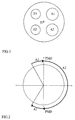
- Figure 1 shows the bottom wall of the cylinder head, defining the combustion chamber, with the orifices of the two intake ducts A1 and A2 and the orifices of the two exhaust conduits E1 and E2.
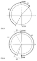
- FIG. 2 shows a first embodiment of the present invention involving the intake valves.
- the PMH reference represents the top dead center of the piston and the PMB reference the dead center low.
- valve A1 is open when the piston is in the ascending phase (i.e. after the bottom dead center PMB or before the top dead center TDC). Under the action of piston, the gases are expelled through the orifice of valve A1, which initializes a aér swirl ⁇ type aerodynamic rotary movement. To maintain this movement, when passing from top dead center TDC, valve A1 is closed, while valve A2 is open. With the piston descending, the gases are sucked in through valve port A2 and aerodynamic movement is maintained, even amplified.
- Another embodiment of the present invention consists in use exhaust valves to initiate movement aerodynamic rotary Figure 3 represents a law of opening of the valves for such an embodiment.
- the exhaust valves are open one after the other following the movement of the piston.
- the exhaust valve E2 is open shortly before or after the bottom dead center PMB remains open during the ascending phase of the piston up to TDC top dead center.
- the gases escape, under the pressure of the piston, through this orifice, generating a odynam swirl ⁇ type aerodynamic movement.
- the sequence of valve opening sequences intake or exhaust can be done in two different modes depending on whether we want to support the aerodynamic movement started, or on the contrary thwart its evolution.
- the E2 valve initiated the aerodynamic movement during most of the ascending phase of the piston, the E1 valve possibly opening after top dead center as in figure 3.
- each of the two modes described above may have its interest on combustion or on the preparation of the mixture.
- This valve overlap can be managed and used for set the desired level of aerodynamic movement ⁇ swirl ⁇ ,
- the recovery periods will be more or less extended depending on the desired level of aerodynamic movement ⁇ swirl ⁇ , this level being a function of the filling, of the recirculation of the burnt gases, or else stratification of the desired mixture.
- Modes [a] and [b] adapt well with a control strategy of the load requiring overall opening spreads greater than half a turn.
- a variant of the invention consists in combining these different strategies with intake or exhaust ducts arranged so as to favor the creation of aerodynamic movement of the type ⁇ swirl ⁇ , or comprising means capable of fulfilling the same function.
- conduits can cause movements ⁇ swirl ⁇ type generated by the two intake ducts, during the same displacement of the piston, are in the same direction. It can be the same for the exhaust pipes.
- a valve control according to the present invention by a camless system allows movement control odynam swirl ⁇ type aerodynamics by promoting or preventing, depending on needs, the rotation of the gases in the combustion chamber.
Landscapes
- Engineering & Computer Science (AREA)
- Mechanical Engineering (AREA)
- General Engineering & Computer Science (AREA)
- Chemical & Material Sciences (AREA)
- Combustion & Propulsion (AREA)
- Output Control And Ontrol Of Special Type Engine (AREA)
- Valve Device For Special Equipments (AREA)
Abstract
Description
Claims (13)
- Procédé de commande d'un moteur à combustion interne, du type comportant au moins un cylindre dans lequel coulisse un piston, ce dernier délimitant, avec une culasse, une chambre de combustion dans laquelle débouchent, par des orifices appropriés, des conduits d'admission de l'air comburant ou du mélange carburé, et des conduits d'échappement pour évacuer les gaz brûlés, les orifices d'admission et d'échappement étant munis de soupapes manoeuvrées par des moyens de commande, au moins une partie desdits conduits étant adaptés pour générer, dans la chambre, lors de l'ouverture des soupapes correspondantes, un mouvement aérodynamique ordonné de type rotatif dont le sens de rotation s'inverse avec le sens de déplacement du piston dans le cylindre, caractérisé en ce que, dans des conditions de fonctionnement moteur prédéterminées, les ouvertures des soupapes d'au moins deux desdits conduits, adaptés pour générer un mouvement aérodynamique, sont opérées séquentiellement selon le sens de déplacement du piston pour contrôler le sens de rotation du mouvement aérodynamique dans la chambre, généré par les conduits correspondants.
- Procédé de commande d'un moteur à combustion interne selon la revendication 1, caractérisé en ce que les ouvertures des soupapes, d'au moins deux desdits conduits adaptés, sont opérées séquentiellement, selon le sens de déplacement du piston, pour que le sens du mouvement aérodynamique généré par les conduits correspondants soit toujours le même.
- Procédé de commande d'un moteur à combustion interne selon la revendication 2, caractérisé en ce qu'il comporte un premier conduit d'admission générant un mouvement rotatif dans un sens lors du mouvement descendant du piston, et un second conduit d'admission générant un mouvement rotatif dans le sens opposé lors du mouvement descendant du piston, et que l'ouverture de la première soupape d'admission est opérée principalement lors du mouvement ascendant du piston tandis que l'ouverture de la seconde soupape d'admission est opérée principalement lors du mouvement descendant du piston.
- Procédé de commande d'un moteur à combustion interne selon la revendication 2, caractérisé en ce qu'il comporte deux conduits d'admission générant un mouvement rotatif de même sens lors d'un même déplacement du piston et que l'ouverture des deux conduits d'admission est opérée principalement lors d'un même déplacement du piston.
- Procédé de commande d'un moteur à combustion interne selon l'une quelconque des revendications 2 à 4, caractérisé en ce qu'il comporte un premier conduit d'échappement générant un mouvement rotatif dans un sens lors du mouvement ascendant du piston, et un second conduit d'échappement générant un mouvement rotatif dans le sens opposé lors du mouvement ascendant du piston, et que l'ouverture de la première soupape d'échappement est opérée principalement lors du mouvement descendant du piston tandis que l'ouverture de la seconde soupape d'échappement est opérée principalement lors du mouvement ascendant du piston.
- Procédé de commande d'un moteur à combustion selon l'une quelconque des revendications 2 à 4, caractérisé en ce qu'il comporte deux conduits d'échappement générant un mouvement rotatif de même sens lors d'un même déplacement du piston et que l'ouverture des deux conduits d'échappement est opérée principalement lors d'un même déplacement du piston.
- Procédé de commande d'un moteur à combustion interne selon l'une quelconque des revendications 2 à 6, caractérisé en ce qu'il comporte un conduit d'échappement générant un mouvement rotatif dans un sens lors du mouvement ascendant du piston, et un conduit d'admission générant un mouvement rotatif dans le sens opposé lors du mouvement ascendant du piston, et que l'ouverture de la soupape d'échappement est opérée principalement lors du mouvement ascendant du piston tandis que l'ouverture de la soupape d'admission est opérée principalement lors du mouvement descendant du piston.
- Procédé de commande d'un moteur à combustion interne selon la revendication 1, caractérisé en ce que les ouvertures des soupapes, d'au moins deux desdits conduits adaptés, sont opérées séquentiellement, selon le sens de déplacement du piston, pour que le sens du mouvement aérodynamique généré par les conduits correspondants soit alternativement de sens opposé.
- Procédé de commande d'un moteur à combustion interne selon la revendication 8, caractérisé en ce qu'il comporte un premier conduit d'admission générant un mouvement rotatif dans un sens lors du mouvement descendant du piston, et un second conduit d'admission générant un mouvement rotatif dans le sens opposé lors du mouvement descendant du piston, et que l'ouverture des deux conduits d'admission est opérée principalement lors d'un même déplacement du piston.
- Procédé de commande d'un moteur à combustion interne selon la revendication 8, caractérisé en ce qu'il comporte deux conduits d'admission générant un mouvement rotatif de même sens lors d'un même déplacement du piston, et que l'ouverture de la première soupape d'admission est opérée principalement lors du mouvement ascendant du piston tandis que l'ouverture de la seconde soupape d'admission est opérée principalement lors du mouvement descendant du piston.
- Procédé de commande d'un moteur à combustion interne selon la revendication 8 à 10, caractérisé en ce qu'il comporte un premier conduit d'échappement générant un mouvement rotatif dans un sens lors du mouvement ascendant du piston, et un second conduit d'échappement générant un mouvement rotatif dans le sens opposé lors du mouvement ascendant du piston, et que l'ouverture des deux conduits d'échappement est opérée principalement lors d'un même déplacement du piston..
- Procédé de commande d'un moteur à combustion interne selon la revendication 8 à 10, caractérisé en ce qu'il comporte deux conduits d'échappement générant un mouvement rotatif de même sens lors d'un même déplacement du piston, et que l'ouverture de la première soupape d'échappement est opérée principalement lors du mouvement descendant du piston tandis que l'ouverture de la seconde soupape d'échappement est opérée principalement lors du mouvement ascendant du piston.
- Procédé de commande d'un moteur à combustion interne selon l'une quelconque des revendications 8 à 12, caractérisé en ce qu'il comporte un conduit d'échappement et un conduit d'admission générant un mouvement rotatif dans un même sens lors du mouvement ascendant du piston, et que l'ouverture de la soupape d'échappement est opérée principalement lors du mouvement ascendant du piston tandis que l'ouverture de la soupape d'admission est opérée principalement lors du mouvement descendant du piston.
Applications Claiming Priority (2)
| Application Number | Priority Date | Filing Date | Title |
|---|---|---|---|
| FR9900373A FR2788558B1 (fr) | 1999-01-15 | 1999-01-15 | Procede de commande d'un moteur a combustion interne |
| FR9900373 | 1999-01-15 |
Publications (1)
| Publication Number | Publication Date |
|---|---|
| EP1020622A1 true EP1020622A1 (fr) | 2000-07-19 |
Family
ID=9540881
Family Applications (1)
| Application Number | Title | Priority Date | Filing Date |
|---|---|---|---|
| EP00400090A Withdrawn EP1020622A1 (fr) | 1999-01-15 | 2000-01-14 | Procédé de commande d'un moteur à combustion interne |
Country Status (2)
| Country | Link |
|---|---|
| EP (1) | EP1020622A1 (fr) |
| FR (1) | FR2788558B1 (fr) |
Families Citing this family (1)
| Publication number | Priority date | Publication date | Assignee | Title |
|---|---|---|---|---|
| ITTO20020571A1 (it) * | 2002-07-01 | 2004-01-02 | Fiat Ricerche | Motore a combustione interna con due valvole di aspirazione per ciascun cilindro e sistema a controllo elettronico per azionare le due valvo |
Citations (4)
| Publication number | Priority date | Publication date | Assignee | Title |
|---|---|---|---|---|
| JPS60212619A (ja) * | 1984-04-09 | 1985-10-24 | Toyota Motor Corp | 複吸気弁エンジンの制御方法 |
| DE3600408A1 (de) * | 1986-01-09 | 1987-07-16 | Audi Ag | Hubkolbenbrennkraftmaschine |
| US5373817A (en) * | 1993-12-17 | 1994-12-20 | Ford Motor Company | Valve deactivation and adjustment system for electrohydraulic camless valvetrain |
| US5669341A (en) * | 1994-05-06 | 1997-09-23 | Honda Giken Kogyo Kabushiki Kaisha | Valve operating system for internal combustion engine |
-
1999
- 1999-01-15 FR FR9900373A patent/FR2788558B1/fr not_active Expired - Fee Related
-
2000
- 2000-01-14 EP EP00400090A patent/EP1020622A1/fr not_active Withdrawn
Patent Citations (4)
| Publication number | Priority date | Publication date | Assignee | Title |
|---|---|---|---|---|
| JPS60212619A (ja) * | 1984-04-09 | 1985-10-24 | Toyota Motor Corp | 複吸気弁エンジンの制御方法 |
| DE3600408A1 (de) * | 1986-01-09 | 1987-07-16 | Audi Ag | Hubkolbenbrennkraftmaschine |
| US5373817A (en) * | 1993-12-17 | 1994-12-20 | Ford Motor Company | Valve deactivation and adjustment system for electrohydraulic camless valvetrain |
| US5669341A (en) * | 1994-05-06 | 1997-09-23 | Honda Giken Kogyo Kabushiki Kaisha | Valve operating system for internal combustion engine |
Non-Patent Citations (1)
| Title |
|---|
| PATENT ABSTRACTS OF JAPAN vol. 010, no. 066 (M - 461) 15 March 1986 (1986-03-15) * |
Also Published As
| Publication number | Publication date |
|---|---|
| FR2788558A1 (fr) | 2000-07-21 |
| FR2788558B1 (fr) | 2001-02-09 |
Similar Documents
| Publication | Publication Date | Title |
|---|---|---|
| EP2083155B1 (fr) | Procédé de balayage des gaz brûlés résiduels avec une double levée de soupape d'admission d'un moteur à combustion interne suralimenté à injection directe, notamment de type Diesel | |
| EP1726805B1 (fr) | Procédé de contrôle du balayage des gaz brûlés d'un moteur à injection indirecte, notamment moteur suralimenté, et moteur utilisant un tel procédé | |
| EP1914409B1 (fr) | Procédé de contrôle d'un moteur à combustion interne et moteur utilisant un tel procédé | |
| EP1195505B1 (fr) | Procédé de contrôle d'auto-allumage dans un moteur à quatre temps | |
| EP1700016B1 (fr) | Procede de controle d'un moteur suralimente, notamment d'un moteur a injection indirecte | |
| FR2955358A1 (fr) | Procede de balayage des gaz brules residuels d'un moteur multi cylindres a combustion interne suralimente a injection directe fonctionnant a charges partielles | |
| EP0953744B1 (fr) | Procédé de combustion par auto-allumage contrôle et moteur 4 temps associié avec volume de stockage de gaz résiduels et soupape dédiée | |
| EP1870583A1 (fr) | Procédé pour commander un moteur à combustion interne | |
| FR2922955A1 (fr) | Procede pour controler la quantite de gaz d'echappement recircules par voie interne d'un moteur a combustion interne de type diesel. | |
| EP2166198B1 (fr) | Moteur à combustion interne du type à fonctionnement dégradé d'au moins un cylindre | |
| EP1544434B1 (fr) | Procédé de commande d'un moteur à combustion interne suralimenté | |
| FR2788558A1 (fr) | Procede de commande d'un moteur a combustion interne | |
| EP2354498B1 (fr) | Procédé de balayage des gaz brûles résiduels d'un moteur multi cylindres à combustion interne suralimenté à injection directe | |
| FR2868481A1 (fr) | Procede de controle de la recirculation des gaz d'echappement d'un moteur suralimente a combustion interne et moteur utilisant un tel procede | |
| FR2654464A1 (fr) | Systeme de fermeture et d'ouverture rapides de la section d'ecoulement de fluide d'un conduit, et moteur thermique a deux temps incorporant ledit systeme. | |
| EP1207288B1 (fr) | Procédé de commande d'un moteur à combustion interne en vue de réaliser une combustion homogène | |
| FR2668798A1 (fr) | Moteur deux temps. | |
| EP2674601A1 (fr) | Procédé de balayage des gaz brûlés résiduels par double levée de soupapes pour un moteur à deux temps, notamment de type Diesel. | |
| EP1870568B1 (fr) | Moteur à combustion interne à injection indirecte, notamment moteur suralimenté à allumage commandé avec deux moyens d'admission pour réaliser une phase de balayage de gaz brûles | |
| FR2877054A1 (fr) | Moteur a combustion interne diesel ou essence a injection directe a taux de gaz brules augmente | |
| FR2795133A1 (fr) | Procede de commande d'un moteur a combustion en vue de l'obtention d'un effet de frein moteur | |
| EP2273086A1 (fr) | Procédé de contrôle de l'admission d'un moteur à combustion interne suralimenté comportant une opération de balayage des gaz brûlés | |
| FR2860552A1 (fr) | Procede de commande d'un moteur suralimente et moteur a combustion interne correspondant | |
| FR2925127A1 (fr) | Moteur a combustion interne du type a cylindres selectivement actifs ou inactifs avec un dispositif de controle de son alimentation en air | |
| BE558591A (fr) |
Legal Events
| Date | Code | Title | Description |
|---|---|---|---|
| PUAI | Public reference made under article 153(3) epc to a published international application that has entered the european phase |
Free format text: ORIGINAL CODE: 0009012 |
|
| AK | Designated contracting states |
Kind code of ref document: A1 Designated state(s): DE ES GB IT |
|
| AX | Request for extension of the european patent |
Free format text: AL;LT;LV;MK;RO;SI |
|
| RIN1 | Information on inventor provided before grant (corrected) |
Inventor name: DESJARDINS, GEORGES |
|
| 17P | Request for examination filed |
Effective date: 20010119 |
|
| AKX | Designation fees paid |
Free format text: DE ES GB IT |
|
| 17Q | First examination report despatched |
Effective date: 20020425 |
|
| RAP1 | Party data changed (applicant data changed or rights of an application transferred) |
Owner name: RENAULT S.A.S. |
|
| GRAH | Despatch of communication of intention to grant a patent |
Free format text: ORIGINAL CODE: EPIDOS IGRA |
|
| STAA | Information on the status of an ep patent application or granted ep patent |
Free format text: STATUS: THE APPLICATION HAS BEEN WITHDRAWN |
|
| 18W | Application withdrawn |
Effective date: 20030530 |