EP1018755A2 - Electrochemical capacitors - Google Patents
Electrochemical capacitors Download PDFInfo
- Publication number
- EP1018755A2 EP1018755A2 EP00100071A EP00100071A EP1018755A2 EP 1018755 A2 EP1018755 A2 EP 1018755A2 EP 00100071 A EP00100071 A EP 00100071A EP 00100071 A EP00100071 A EP 00100071A EP 1018755 A2 EP1018755 A2 EP 1018755A2
- Authority
- EP
- European Patent Office
- Prior art keywords
- separators
- electrochemical capacitor
- electrolytic solution
- polarizing electrodes
- organic electrolytic
- Prior art date
- Legal status (The legal status is an assumption and is not a legal conclusion. Google has not performed a legal analysis and makes no representation as to the accuracy of the status listed.)
- Withdrawn
Links
- 239000003990 capacitor Substances 0.000 title claims abstract description 191
- 238000007600 charging Methods 0.000 claims abstract description 65
- 239000008151 electrolyte solution Substances 0.000 claims abstract description 64
- OKTJSMMVPCPJKN-UHFFFAOYSA-N Carbon Chemical compound [C] OKTJSMMVPCPJKN-UHFFFAOYSA-N 0.000 claims abstract description 53
- 239000003575 carbonaceous material Substances 0.000 claims abstract description 52
- 238000007599 discharging Methods 0.000 claims abstract description 39
- 229910052799 carbon Inorganic materials 0.000 claims abstract description 31
- 150000002500 ions Chemical class 0.000 claims abstract description 28
- 229920001971 elastomer Polymers 0.000 claims abstract description 25
- 239000003792 electrolyte Substances 0.000 claims abstract description 25
- 239000000806 elastomer Substances 0.000 claims abstract description 19
- 239000012212 insulator Substances 0.000 claims abstract description 14
- 239000002075 main ingredient Substances 0.000 claims abstract description 13
- 230000002040 relaxant effect Effects 0.000 claims abstract description 11
- 150000001768 cations Chemical class 0.000 claims abstract description 9
- 239000011148 porous material Substances 0.000 claims abstract description 7
- 239000000463 material Substances 0.000 claims description 19
- 239000001913 cellulose Substances 0.000 claims description 11
- 229920002678 cellulose Polymers 0.000 claims description 11
- 229910052782 aluminium Inorganic materials 0.000 claims description 10
- XAGFODPZIPBFFR-UHFFFAOYSA-N aluminium Chemical compound [Al] XAGFODPZIPBFFR-UHFFFAOYSA-N 0.000 claims description 10
- 239000004745 nonwoven fabric Substances 0.000 claims description 10
- 239000004744 fabric Substances 0.000 claims description 5
- 230000005489 elastic deformation Effects 0.000 claims description 4
- 239000000835 fiber Substances 0.000 claims description 3
- 239000012784 inorganic fiber Substances 0.000 claims description 2
- 239000005373 porous glass Substances 0.000 claims 1
- 239000002904 solvent Substances 0.000 description 31
- 238000010276 construction Methods 0.000 description 17
- 239000000203 mixture Substances 0.000 description 16
- 230000000052 comparative effect Effects 0.000 description 15
- 239000011230 binding agent Substances 0.000 description 14
- -1 polytetrafluoroethylene Polymers 0.000 description 14
- KWYUFKZDYYNOTN-UHFFFAOYSA-M Potassium hydroxide Chemical compound [OH-].[K+] KWYUFKZDYYNOTN-UHFFFAOYSA-M 0.000 description 12
- 238000002156 mixing Methods 0.000 description 11
- IJGRMHOSHXDMSA-UHFFFAOYSA-N Atomic nitrogen Chemical compound N#N IJGRMHOSHXDMSA-UHFFFAOYSA-N 0.000 description 10
- 239000011368 organic material Substances 0.000 description 10
- 238000007254 oxidation reaction Methods 0.000 description 9
- RUOJZAUFBMNUDX-UHFFFAOYSA-N propylene carbonate Chemical compound CC1COC(=O)O1 RUOJZAUFBMNUDX-UHFFFAOYSA-N 0.000 description 9
- 238000000034 method Methods 0.000 description 8
- 230000003647 oxidation Effects 0.000 description 8
- YEJRWHAVMIAJKC-UHFFFAOYSA-N 4-Butyrolactone Chemical compound O=C1CCCO1 YEJRWHAVMIAJKC-UHFFFAOYSA-N 0.000 description 7
- 229910019785 NBF4 Inorganic materials 0.000 description 7
- 239000006229 carbon black Substances 0.000 description 7
- 229920001343 polytetrafluoroethylene Polymers 0.000 description 7
- 239000004810 polytetrafluoroethylene Substances 0.000 description 7
- HXJUTPCZVOIRIF-UHFFFAOYSA-N sulfolane Chemical compound O=S1(=O)CCCC1 HXJUTPCZVOIRIF-UHFFFAOYSA-N 0.000 description 7
- KMTRUDSVKNLOMY-UHFFFAOYSA-N Ethylene carbonate Chemical compound O=C1OCCO1 KMTRUDSVKNLOMY-UHFFFAOYSA-N 0.000 description 6
- 229910052783 alkali metal Inorganic materials 0.000 description 6
- 230000008859 change Effects 0.000 description 6
- 239000011888 foil Substances 0.000 description 6
- 239000004033 plastic Substances 0.000 description 6
- 229920003023 plastic Polymers 0.000 description 6
- 150000001340 alkali metals Chemical class 0.000 description 5
- 238000000576 coating method Methods 0.000 description 5
- 239000007772 electrode material Substances 0.000 description 5
- 238000001704 evaporation Methods 0.000 description 5
- 230000008020 evaporation Effects 0.000 description 5
- 239000003365 glass fiber Substances 0.000 description 5
- 239000007788 liquid Substances 0.000 description 5
- 229910052757 nitrogen Inorganic materials 0.000 description 5
- 230000009467 reduction Effects 0.000 description 5
- CBXCPBUEXACCNR-UHFFFAOYSA-N tetraethylammonium Chemical compound CC[N+](CC)(CC)CC CBXCPBUEXACCNR-UHFFFAOYSA-N 0.000 description 5
- 239000007795 chemical reaction product Substances 0.000 description 4
- 239000011248 coating agent Substances 0.000 description 4
- 238000003487 electrochemical reaction Methods 0.000 description 4
- 239000013081 microcrystal Substances 0.000 description 4
- OKKJLVBELUTLKV-UHFFFAOYSA-N Methanol Chemical compound OC OKKJLVBELUTLKV-UHFFFAOYSA-N 0.000 description 3
- HEMHJVSKTPXQMS-UHFFFAOYSA-M Sodium hydroxide Chemical compound [OH-].[Na+] HEMHJVSKTPXQMS-UHFFFAOYSA-M 0.000 description 3
- 238000010521 absorption reaction Methods 0.000 description 3
- 239000003513 alkali Substances 0.000 description 3
- 230000008901 benefit Effects 0.000 description 3
- 230000006378 damage Effects 0.000 description 3
- 238000001035 drying Methods 0.000 description 3
- 239000007789 gas Substances 0.000 description 3
- 238000000227 grinding Methods 0.000 description 3
- 238000010438 heat treatment Methods 0.000 description 3
- 230000006872 improvement Effects 0.000 description 3
- 230000001965 increasing effect Effects 0.000 description 3
- 239000004615 ingredient Substances 0.000 description 3
- 239000002245 particle Substances 0.000 description 3
- 239000002006 petroleum coke Substances 0.000 description 3
- 239000000843 powder Substances 0.000 description 3
- 230000008569 process Effects 0.000 description 3
- 239000000047 product Substances 0.000 description 3
- CDBYLPFSWZWCQE-UHFFFAOYSA-L sodium carbonate Substances [Na+].[Na+].[O-]C([O-])=O CDBYLPFSWZWCQE-UHFFFAOYSA-L 0.000 description 3
- 238000001179 sorption measurement Methods 0.000 description 3
- 239000000126 substance Substances 0.000 description 3
- DZLFLBLQUQXARW-UHFFFAOYSA-N tetrabutylammonium Chemical compound CCCC[N+](CCCC)(CCCC)CCCC DZLFLBLQUQXARW-UHFFFAOYSA-N 0.000 description 3
- XLYOFNOQVPJJNP-UHFFFAOYSA-N water Chemical compound O XLYOFNOQVPJJNP-UHFFFAOYSA-N 0.000 description 3
- XKRFYHLGVUSROY-UHFFFAOYSA-N Argon Chemical compound [Ar] XKRFYHLGVUSROY-UHFFFAOYSA-N 0.000 description 2
- OIFBSDVPJOWBCH-UHFFFAOYSA-N Diethyl carbonate Chemical compound CCOC(=O)OCC OIFBSDVPJOWBCH-UHFFFAOYSA-N 0.000 description 2
- LFQSCWFLJHTTHZ-UHFFFAOYSA-N Ethanol Chemical compound CCO LFQSCWFLJHTTHZ-UHFFFAOYSA-N 0.000 description 2
- 230000004913 activation Effects 0.000 description 2
- 150000001339 alkali metal compounds Chemical class 0.000 description 2
- QVGXLLKOCUKJST-UHFFFAOYSA-N atomic oxygen Chemical compound [O] QVGXLLKOCUKJST-UHFFFAOYSA-N 0.000 description 2
- 230000015572 biosynthetic process Effects 0.000 description 2
- 238000003763 carbonization Methods 0.000 description 2
- 238000006243 chemical reaction Methods 0.000 description 2
- 150000001875 compounds Chemical class 0.000 description 2
- 230000008602 contraction Effects 0.000 description 2
- 230000006866 deterioration Effects 0.000 description 2
- 230000000694 effects Effects 0.000 description 2
- 238000005516 engineering process Methods 0.000 description 2
- JBTWLSYIZRCDFO-UHFFFAOYSA-N ethyl methyl carbonate Chemical compound CCOC(=O)OC JBTWLSYIZRCDFO-UHFFFAOYSA-N 0.000 description 2
- 229910002804 graphite Inorganic materials 0.000 description 2
- 239000010439 graphite Substances 0.000 description 2
- 239000011261 inert gas Substances 0.000 description 2
- 230000014759 maintenance of location Effects 0.000 description 2
- 238000002844 melting Methods 0.000 description 2
- 230000008018 melting Effects 0.000 description 2
- 230000005012 migration Effects 0.000 description 2
- 238000013508 migration Methods 0.000 description 2
- 239000001301 oxygen Substances 0.000 description 2
- 229910052760 oxygen Inorganic materials 0.000 description 2
- 230000000149 penetrating effect Effects 0.000 description 2
- BWHMMNNQKKPAPP-UHFFFAOYSA-L potassium carbonate Chemical compound [K+].[K+].[O-]C([O-])=O BWHMMNNQKKPAPP-UHFFFAOYSA-L 0.000 description 2
- 238000003825 pressing Methods 0.000 description 2
- 229920005989 resin Polymers 0.000 description 2
- 239000011347 resin Substances 0.000 description 2
- 150000003839 salts Chemical class 0.000 description 2
- 238000007789 sealing Methods 0.000 description 2
- 239000000243 solution Substances 0.000 description 2
- 238000012360 testing method Methods 0.000 description 2
- GEWWCWZGHNIUBW-UHFFFAOYSA-N 1-(4-nitrophenyl)propan-2-one Chemical compound CC(=O)CC1=CC=C([N+]([O-])=O)C=C1 GEWWCWZGHNIUBW-UHFFFAOYSA-N 0.000 description 1
- NIHOUJYFWMURBG-UHFFFAOYSA-N 1-ethyl-1-methylpyrrolidin-1-ium Chemical compound CC[N+]1(C)CCCC1 NIHOUJYFWMURBG-UHFFFAOYSA-N 0.000 description 1
- CURLTUGMZLYLDI-UHFFFAOYSA-N Carbon dioxide Chemical compound O=C=O CURLTUGMZLYLDI-UHFFFAOYSA-N 0.000 description 1
- UGFAIRIUMAVXCW-UHFFFAOYSA-N Carbon monoxide Chemical compound [O+]#[C-] UGFAIRIUMAVXCW-UHFFFAOYSA-N 0.000 description 1
- BVKZGUZCCUSVTD-UHFFFAOYSA-L Carbonate Chemical compound [O-]C([O-])=O BVKZGUZCCUSVTD-UHFFFAOYSA-L 0.000 description 1
- DGAQECJNVWCQMB-PUAWFVPOSA-M Ilexoside XXIX Chemical compound C[C@@H]1CC[C@@]2(CC[C@@]3(C(=CC[C@H]4[C@]3(CC[C@@H]5[C@@]4(CC[C@@H](C5(C)C)OS(=O)(=O)[O-])C)C)[C@@H]2[C@]1(C)O)C)C(=O)O[C@H]6[C@@H]([C@H]([C@@H]([C@H](O6)CO)O)O)O.[Na+] DGAQECJNVWCQMB-PUAWFVPOSA-M 0.000 description 1
- WHXSMMKQMYFTQS-UHFFFAOYSA-N Lithium Chemical compound [Li] WHXSMMKQMYFTQS-UHFFFAOYSA-N 0.000 description 1
- GRYLNZFGIOXLOG-UHFFFAOYSA-N Nitric acid Chemical compound O[N+]([O-])=O GRYLNZFGIOXLOG-UHFFFAOYSA-N 0.000 description 1
- 239000004677 Nylon Substances 0.000 description 1
- 239000004642 Polyimide Substances 0.000 description 1
- 229920001328 Polyvinylidene chloride Polymers 0.000 description 1
- ZLMJMSJWJFRBEC-UHFFFAOYSA-N Potassium Chemical compound [K] ZLMJMSJWJFRBEC-UHFFFAOYSA-N 0.000 description 1
- 239000006230 acetylene black Substances 0.000 description 1
- 230000002378 acidificating effect Effects 0.000 description 1
- 239000013543 active substance Substances 0.000 description 1
- 239000003570 air Substances 0.000 description 1
- 230000001476 alcoholic effect Effects 0.000 description 1
- 229910001854 alkali hydroxide Inorganic materials 0.000 description 1
- PNEYBMLMFCGWSK-UHFFFAOYSA-N aluminium oxide Inorganic materials [O-2].[O-2].[O-2].[Al+3].[Al+3] PNEYBMLMFCGWSK-UHFFFAOYSA-N 0.000 description 1
- 150000001450 anions Chemical class 0.000 description 1
- 229910052786 argon Inorganic materials 0.000 description 1
- 239000005388 borosilicate glass Substances 0.000 description 1
- 150000001721 carbon Chemical class 0.000 description 1
- 229910002092 carbon dioxide Inorganic materials 0.000 description 1
- 229910002091 carbon monoxide Inorganic materials 0.000 description 1
- 150000004649 carbonic acid derivatives Chemical class 0.000 description 1
- 239000005539 carbonized material Substances 0.000 description 1
- 239000000919 ceramic Substances 0.000 description 1
- 238000004140 cleaning Methods 0.000 description 1
- 239000011335 coal coke Substances 0.000 description 1
- 239000011300 coal pitch Substances 0.000 description 1
- 238000010280 constant potential charging Methods 0.000 description 1
- 238000010277 constant-current charging Methods 0.000 description 1
- 238000001816 cooling Methods 0.000 description 1
- 239000013078 crystal Substances 0.000 description 1
- 238000000354 decomposition reaction Methods 0.000 description 1
- 238000013461 design Methods 0.000 description 1
- IEJIGPNLZYLLBP-UHFFFAOYSA-N dimethyl carbonate Chemical compound COC(=O)OC IEJIGPNLZYLLBP-UHFFFAOYSA-N 0.000 description 1
- 239000012153 distilled water Substances 0.000 description 1
- 238000009837 dry grinding Methods 0.000 description 1
- 239000000428 dust Substances 0.000 description 1
- 230000005684 electric field Effects 0.000 description 1
- 230000005611 electricity Effects 0.000 description 1
- 238000001914 filtration Methods 0.000 description 1
- 125000000524 functional group Chemical group 0.000 description 1
- 239000001307 helium Substances 0.000 description 1
- 229910052734 helium Inorganic materials 0.000 description 1
- SWQJXJOGLNCZEY-UHFFFAOYSA-N helium atom Chemical compound [He] SWQJXJOGLNCZEY-UHFFFAOYSA-N 0.000 description 1
- 150000004679 hydroxides Chemical class 0.000 description 1
- 230000001939 inductive effect Effects 0.000 description 1
- 230000001788 irregular Effects 0.000 description 1
- 229910052744 lithium Inorganic materials 0.000 description 1
- 239000007769 metal material Substances 0.000 description 1
- 229910017604 nitric acid Inorganic materials 0.000 description 1
- 229920001778 nylon Polymers 0.000 description 1
- 150000002894 organic compounds Chemical class 0.000 description 1
- 230000001590 oxidative effect Effects 0.000 description 1
- 125000004430 oxygen atom Chemical group O* 0.000 description 1
- 238000012856 packing Methods 0.000 description 1
- 239000011301 petroleum pitch Substances 0.000 description 1
- 229920001568 phenolic resin Polymers 0.000 description 1
- 239000005011 phenolic resin Substances 0.000 description 1
- 229920001721 polyimide Polymers 0.000 description 1
- 229920000915 polyvinyl chloride Polymers 0.000 description 1
- 239000004800 polyvinyl chloride Substances 0.000 description 1
- 239000005033 polyvinylidene chloride Substances 0.000 description 1
- 229910052700 potassium Inorganic materials 0.000 description 1
- 239000011591 potassium Substances 0.000 description 1
- 229910000027 potassium carbonate Inorganic materials 0.000 description 1
- 150000003112 potassium compounds Chemical class 0.000 description 1
- 238000002360 preparation method Methods 0.000 description 1
- 230000002265 prevention Effects 0.000 description 1
- 238000012545 processing Methods 0.000 description 1
- 239000002994 raw material Substances 0.000 description 1
- 238000005096 rolling process Methods 0.000 description 1
- 229910052708 sodium Inorganic materials 0.000 description 1
- 239000011734 sodium Substances 0.000 description 1
- 229910000029 sodium carbonate Inorganic materials 0.000 description 1
- 235000011182 sodium carbonates Nutrition 0.000 description 1
- 238000005507 spraying Methods 0.000 description 1
- 229910001220 stainless steel Inorganic materials 0.000 description 1
- 239000010935 stainless steel Substances 0.000 description 1
- 238000003860 storage Methods 0.000 description 1
- 238000001238 wet grinding Methods 0.000 description 1
- 210000002268 wool Anatomy 0.000 description 1
Images






Classifications
-
- H—ELECTRICITY
- H01—ELECTRIC ELEMENTS
- H01G—CAPACITORS; CAPACITORS, RECTIFIERS, DETECTORS, SWITCHING DEVICES, LIGHT-SENSITIVE OR TEMPERATURE-SENSITIVE DEVICES OF THE ELECTROLYTIC TYPE
- H01G11/00—Hybrid capacitors, i.e. capacitors having different positive and negative electrodes; Electric double-layer [EDL] capacitors; Processes for the manufacture thereof or of parts thereof
- H01G11/14—Arrangements or processes for adjusting or protecting hybrid or EDL capacitors
-
- H—ELECTRICITY
- H01—ELECTRIC ELEMENTS
- H01G—CAPACITORS; CAPACITORS, RECTIFIERS, DETECTORS, SWITCHING DEVICES, LIGHT-SENSITIVE OR TEMPERATURE-SENSITIVE DEVICES OF THE ELECTROLYTIC TYPE
- H01G11/00—Hybrid capacitors, i.e. capacitors having different positive and negative electrodes; Electric double-layer [EDL] capacitors; Processes for the manufacture thereof or of parts thereof
- H01G11/22—Electrodes
- H01G11/26—Electrodes characterised by their structure, e.g. multi-layered, porosity or surface features
-
- H—ELECTRICITY
- H01—ELECTRIC ELEMENTS
- H01G—CAPACITORS; CAPACITORS, RECTIFIERS, DETECTORS, SWITCHING DEVICES, LIGHT-SENSITIVE OR TEMPERATURE-SENSITIVE DEVICES OF THE ELECTROLYTIC TYPE
- H01G11/00—Hybrid capacitors, i.e. capacitors having different positive and negative electrodes; Electric double-layer [EDL] capacitors; Processes for the manufacture thereof or of parts thereof
- H01G11/54—Electrolytes
- H01G11/58—Liquid electrolytes
- H01G11/62—Liquid electrolytes characterised by the solute, e.g. salts, anions or cations therein
-
- H—ELECTRICITY
- H01—ELECTRIC ELEMENTS
- H01G—CAPACITORS; CAPACITORS, RECTIFIERS, DETECTORS, SWITCHING DEVICES, LIGHT-SENSITIVE OR TEMPERATURE-SENSITIVE DEVICES OF THE ELECTROLYTIC TYPE
- H01G11/00—Hybrid capacitors, i.e. capacitors having different positive and negative electrodes; Electric double-layer [EDL] capacitors; Processes for the manufacture thereof or of parts thereof
- H01G11/78—Cases; Housings; Encapsulations; Mountings
- H01G11/82—Fixing or assembling a capacitive element in a housing, e.g. mounting electrodes, current collectors or terminals in containers or encapsulations
-
- H—ELECTRICITY
- H01—ELECTRIC ELEMENTS
- H01G—CAPACITORS; CAPACITORS, RECTIFIERS, DETECTORS, SWITCHING DEVICES, LIGHT-SENSITIVE OR TEMPERATURE-SENSITIVE DEVICES OF THE ELECTROLYTIC TYPE
- H01G11/00—Hybrid capacitors, i.e. capacitors having different positive and negative electrodes; Electric double-layer [EDL] capacitors; Processes for the manufacture thereof or of parts thereof
- H01G11/52—Separators
-
- Y—GENERAL TAGGING OF NEW TECHNOLOGICAL DEVELOPMENTS; GENERAL TAGGING OF CROSS-SECTIONAL TECHNOLOGIES SPANNING OVER SEVERAL SECTIONS OF THE IPC; TECHNICAL SUBJECTS COVERED BY FORMER USPC CROSS-REFERENCE ART COLLECTIONS [XRACs] AND DIGESTS
- Y02—TECHNOLOGIES OR APPLICATIONS FOR MITIGATION OR ADAPTATION AGAINST CLIMATE CHANGE
- Y02E—REDUCTION OF GREENHOUSE GAS [GHG] EMISSIONS, RELATED TO ENERGY GENERATION, TRANSMISSION OR DISTRIBUTION
- Y02E60/00—Enabling technologies; Technologies with a potential or indirect contribution to GHG emissions mitigation
- Y02E60/13—Energy storage using capacitors
Definitions
- the present invention relates to electrochemical capacitors wherein reliability and durability are improved by reducing the pressure generated by change in volume accompanying charging and discharging, when high-performance carbon materials with large electrostatic capacity are used as polarizing electrodes.
- the present invention also relates to electrostatic capacitors having structures relaxing the stress generated by expansion of the polarizing electrodes on charging.
- electric double layer capacitors a type of capacitors, are investigated to use for the purpose of off-peak power storage from the view point of effective utilization of energy.
- a single electrode cell 10 one of the basic structures of such electric double layer capacitors, has the structure as shown in Fig. 15 in which a positive side polarizing electrode 24 and a negative side polarizing electrode 26 are respectively formed on collectors 20 and 22 generally comprised of metallic materials, said polarizing electrodes 24 and 26 being separated by a separator 28, and are impregnated with electrolytic solution comprising the solvent and electrolytes.
- Fig. 16 shows the structure of a single capacitor cell 12, wherein plurality of single electrode cells 10 are electrically connected parallel with each other to electrode outlet parts 30 and 32 formed on collectors 20 and 22.
- a single capacitor cell 12 is suitably used as an electric double layer capacitor with relatively large capacity used for automobiles, etc.
- Both single electrode cells 10 or single capacitor cells 12 are planar and characterized by easiness of tight packing and expansion.
- a coil type electric double layer capacitor 70 is prepared using a coil 76 prepared by cylindrically coiling a positive electrode sheet 72, in which a positive electrode side polarizing electrode 24 is formed on a collector 20, and a negative electrode sheet 74, in which a negative pole side polarizing electrode 26 is formed on a collector 22, with a separator 28 between them, and for example by putting said coil 76 in a case 78 and fill the case with electrolytic solution, and sealing the opening end surface of the case 78 with a sealing plate 82 having an electrode terminal 80 formed on it, while securing continuity between electrode sheets 72 and 74 and each electrode terminal 80.
- polarizing electrode materials for such electric double layer capacitors those having activated carbon with relative surface area of 1000 m 2 or more as a main ingredient have traditionally been used.
- the construction of a pair of electrode of an electric double layer capacitor using such activated carbons will be explained referring to Fig. 18.
- this pair of electrodes 1 is constructed to have a positive pole 2 and a negative pole 3 stuck to one another with a separator 6 between them.
- the positive pole 2 and the negative pole 3 have layers of polarizing electrodes 5 containing activated carbon as an essential ingredient and optionally binders such as polytetrafluoroethylene and conduction aids such as carbon black, on the surface of a collector 4 comprising aluminum foil, etc.
- polarizing electrodes 5 containing activated carbon as an essential ingredient and optionally binders such as polytetrafluoroethylene and conduction aids such as carbon black, on the surface of a collector 4 comprising aluminum foil, etc.
- the layer of polarizing electrode 5 is formed for example by blending a mixture of fixed ratio of activated carbon, a binder and a conduction aid to give a sheet of fixed shape and area, which is then adhered onto a collector 4. It may also be formed by coating the surface of a collector 4 with a paste of a mixture of activated carbon, a binder, a conduction aid, and a solvent and drying it to remove the solvent by evaporation. Known coating methods such as spray coating and brush coating may be adopted.
- the separator 6 is impregnated with an organic electrolytic solution (not shown) such as ethylene carbonate, propylene carbonate, ⁇ -butyrolactone, and sulfolane, containing a fixed concentration, for example, of 1 mol/l of an electrolyte such as Et 4 NBF 4 (Et 4 N; tetraethylammonium), Et 4 NPF 6 , Bu 4 NBF 4 (Bu 4 N: tetrabutylammonium) or Bu 4 NPF 6 .
- an organic electrolytic solution such as ethylene carbonate, propylene carbonate, ⁇ -butyrolactone, and sulfolane, containing a fixed concentration, for example, of 1 mol/l of an electrolyte such as Et 4 NBF 4 (Et 4 N; tetraethylammonium), Et 4 NPF 6 , Bu 4 NBF 4 (Bu 4 N: tetrabutylammonium) or Bu 4 NPF 6 .
- Cellulose blend paper is particularly suitable. Cellulose blend paper also has advantages that it is inexpensive enabling cost reduction, and may be formed thinner enabling reduction of internal resistance of the electric double layer capacitor.
- cellulose blend paper will not melt even when the positive and negative electrodes shorts, as it has high melting point. Therefore, it is seldom used as electric cell separators. This is because migration of electrolyte ions is not prevented, as ion penetrating pores of the separator is not blocked even when internal temperature of an electric cell rises due to excessive reaction of the cell when elctrodes short, resulting in further rise of the internal temperature.
- Capacitance and upper limited voltage of conventional electric double layer capacitors described above depend on the activation method of activated carbon. For example, capacitance is 15 F/cc and upper limited voltage is 3 V for an electrochemical capacitor using steam-activated carbons, and capacitance is 20 F/cc and upper limited voltage is 2.5 V for an electrochemical capacitor using alkali-activated carbons.
- Capacitance and upper limited voltage of various capacitors including electrical double layer capacitors are expected recently to improve further, those with these values above 30 F/cc and 3.5 V being desired.
- alkali-activated new polarizing electrode materials are reported in Japanese patent provisional publications No. 275042/1997 and 320906/1997 in order to increase the capacity of polarizing electrode materials.
- This volume expansion tends to increase as the amount of electricity contributing to charging and discharging, and is especially a big problem in uses wherein it is preferable that capacitance is big, charging and discharging capacity is big, and further capacitance density (density of capacitance for unit volume) or capacitance weight-density (density of capacitance for unit weight) is big, especially as in automobiles.
- single capacitor cells 12 are tightly packed in a capacitor case (to be called “case” hereafter) with least opening in order to make the capacitance density as large as possible.
- electrode outlets 30, 32 are formed in the direction perpendicular to the direction of stacking of single electrode cells 10 constructing single capacitor cells 12
- separators 28 are designed to have areas larger than those of polarizing electrodes 24, 26, and the polarizing electrodes 24, 26 expand little in the direction perpendicular to the direction of stacking. Therefore polarizing electrodes 24,26 do not hardly touch the internal walls of the case directly, so that they are not susceptible to volume expansion described above.
- the single capacitor cells 12 may not be held stably in the case causing problems of increased internal resistance and greater deviation of capacitance, that would reduce stability of properties. Such problems would be especially greater under circumstances where there is constant vibration as in the case of being installed in automobiles.
- coil-type electric double layer capacitors 70 can be considered to have structures wherein polarizing electrodes are stacked in the direction of the core, the problem of volume expansion of polarizing electrodes in the electrochemical capacitors having a coil-type structure may be considered in the same manner as in the case of single capacitor cells 12.
- surface pressure is applied onto the cylindrical wall of the case, that would cause deformation or destruction of the case with greater possibility.
- the present invention was made in view of the problems of conventional technology described above, with the purpose of providing electrochemical capacitors in which reduction of occurring surface pressure is enabled without reducing capacitance by paying attention to electrolytes of organic electrolytic solutions used in electrochemical capacitors.
- Another purpose of the present invention is to provide electrolytic capacitors showing capacitance and upper limited voltage that are superior to those of electric double layer capacitors using activated carbon.
- an electrochemical capacitor comprising:
- an electrochemical capacitor comprising:
- an electrochemical capacitor comprising:
- the electrode structure is preferably in the oppressed condition under the pressure of 2 kgf/cm 2 (196 kPa) or more.
- an electrochemical capacitor comprising:
- cloth or nonwoven fabric having at least inorganic fibers is preferably used as the porous insulators. It is also preferable to use polymeric materials as the porous insulators.
- the electrochemical capacitors will not run short of organic electrolytic solution by using, as the separators, sponge-like materials that can be impregnated with large amounts of organic electrolytic solution. Further, as these separators are easily deformable, polarizing electrodes will not go through the separators even when expanded. Thus, the positive and negative poles may not short.
- Electrochemical capacitors of the present invention have polarizing electrodes comprising as the main ingredient carbon materials having partially oxidized graphite-like microcrystalline carbon, impregnated with an organic electrolytic solution, said polarizing electrodes being characterized by volume expansion on charging and volume contraction on discharging.
- polarizing electrodes comprising as the main ingredient carbon materials having partially oxidized graphite-like microcrystalline carbon, impregnated with an organic electrolytic solution, said polarizing electrodes being characterized by volume expansion on charging and volume contraction on discharging.
- Organic materials such as petroleum cokes, coal cokes, petroleum pitch (tar), coal pitch (tar), phenolic resins, meso phase carbon, polyvinyl chloride, polyvinylidene chloride, polyimide, palm shell, and saw dust are first thermally treated in an inert circumstance, around the temperature range of about 700-1000°C to obtain the carbon material.
- Organic materials such as petroleum cokes, coal cokes, petroleum pitch (tar), coal pitch (tar), phenolic resins, meso phase carbon, polyvinyl chloride, polyvinylidene chloride, polyimide, palm shell, and saw dust are first thermally treated in an inert circumstance, around the temperature range of about 700-1000°C to obtain the carbon material.
- Either one kind of organic material alone or a mixture of plurality of organic materials may be used.
- Nitrogen or rare gases such as argon and helium may be suitably used.
- the carbon material obtained above is preferably ground to have fixed particle size. Grinding is not necessary, here, in case the carbon material is obtained in a form of powder, for instance as the organic material is in the form of powder. Uniformity in the partial oxidation reaction and reduction of the time for oxidation may be realized by this grinding. Various known methods of either dry or wet grinding may be used.
- carbon materials having graphite-like microcrystalline carbon can be obtained by partial oxidation of the powdery carbon materials obtained above.
- partial oxidation here, besides heat treatment with oxidative gases such as air and oxygen, and chemical oxidation methods using for example hot nitric acid, oxidation methods by thermally treating the organic materials in the presence of at least one kind of alkali metal compound (to be called "alkali metals” hereafter) containing alkali metal and oxygen atoms below carbonation temperature of the organic materials in an inert gas atmosphere.
- Potassium, sodium, and lithium are suitably used as the alkali metal elements, and hydroxides such as potassium hydroxide and sodium hydroxide and carbonates such as potassium carbonate and sodium carbonate are suitably used as the oxygen-containing compounds of alkali metals.
- These alkali metals and their compounds may be used as mixtures of two or more kinds.
- Carbonized materials are thermally treated together with at least one alkali metal or alkali metal compound below decomposition temperature of organic materials in an inert gas atmosphere, and then washed with alcoholic solvents such as methanol and ethanol or distilled water, and filtered to obtain the carbon materials used for polarizing electrodes.
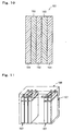
- Graphite-like microcrystalline carbon denotes regularly layered microcrystalline carbon 95 of 0.1 nm - tens nm among this carbon of random layered structure 90 and 91.
- Carbon of random layered structure 90 of Fig. 13 (A) has a structure wherein carbon microcrystals 95 are stack at irregular angles with each other, with their layer planes oriented nearly parallel but not completely parallel. Such carbon of random layered structure 90 is found often in case organic materials easily converted to graphite during the carbonization process.
- carbon of random layered structure 91 of Fig. 13(B) has a structure wherein carbon microcrystals 95 are randomly oriented in network forms, often found in case organic materials difficultly turned to graphite during the carbonization process.
- Fig. 14 schematically illustrates a form of molecular structure of the carbon material, and that it does not mean that the carbon materials of the present invention are limited to those with the structure of Fig. 14.
- Polarizing electrode are now prepared with the carbon materials described above as the main ingredient. Preparation of this polarizing electrode is carried out by adding organic binder and conduction aids such as carbon black to the carbon material, mixing and blending them, and processing the product into various forms such as plates and sheets.
- the carbon materials can be used as materials for polarizing electrodes regardless of capacitor structures, and capacitors with various structures are produced, for example, by putting the polarizing electrodes in the cases as single electrode cells 10 shown in Fig. 15, and single capacitor cells 12 shown in Fig. 16, and further as structures such as coil-type capacitors shown in Fig. 17, impregnating them with organic electrolytic solutions.
- organic electrolytic solutions for these capacitors containing electrolyte cations with ionic radii of 0.33 nm or less are used.
- the capacitors of the present invention are those in which solutes comprising ions with positive charges, namely cations, with ionic radii of 0.33 nm or less when the solute is dissolved in the organic electrolytic solution and exist as ions.
- This ionic radii was decided using the ionic radius (0.343 nm) of tetraethylammonium, conventionally used as a standard electrolyte, as the standard reference.
- ions with such ionic radii are trimethylethylammonium ions (ionic radii: 0.319 nm) and methylethylpyrrolidinium (ionic radii: 0.327 nm).
- tetrafluoroborate ion and hexafluorophosphate ion are suitable selected.
- BF 4 salts or PF 6 salts of trimethyammonium or methlethylpyrrolidinium are suitably used.
- solvents for electrolytic solutions those containing at least one of propylene carbonate (PC), ⁇ -butyrolactone (GBL), ethylene carbonate (EC), sulfolane (SL) are suitably used. Also, it is possible to use those comprising at least one of said PC, GBL, EC, and SL as main solvents, and those comprising at least one of dimethyl carbonate (DMC), ethylmethyl carbonate (EMC), and diethyl carbonate (DEC) as auxiliary solvents.
- PC propylene carbonate
- GBL ⁇ -butyrolactone
- EC ethylene carbonate
- SL sulfolane
- the main solvent means a solvent that can serve sufficiently as an electrolytic solvent even alone
- the auxiliary solvent means a solvent that alone may serve poorly as an electrolytic solvent, but its combination with a main solvent can serve better than the main solvent or the auxiliary solvent alone, and there is no limitation in the amount of the auxiliary solvent such as less than 50%.
- a single cell 107 of the conventional capacitor is shown in Fig. 8.
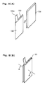
- This single cell 107 put in a cell container 106, is a stack 105 formed by alternatingly stacking plurality of electrode members 101, shown in Fig. 9 (A), Fig. 9 (B), and Fig. 10, that serve as positive and negative poles, and then bundling outlets 102a of each electrodes.
- the electrode member connected to the positive terminal serves as a positive pole
- the electrode member connected to the negative terminal serves as a negative pole.
- the electrode members 101 are constructed as shown in Fig. 9 (A), wherein collectors 102 having electrode outlets 102a are held between sheets of polarizing electrodes 103, and the products are further held between separators 104 as shown in Fig. 9 (B).
- Aluminum foil and a blend paper, processed into determined shapes, may be used as collectors 102 and separators 104 respectively.
- FIG. 9 cross-sectional view of Fig. 9 (B) indicated by arrows at A-A may appear as shown in Fig. 10.
- the sheets of polarizing electrodes 103 can be obtained by blending activated carbon, binders such as polytetrafluoroethylene, and conduction aids such as carbon black together, and rolling the product.
- Electrodes are those obtained by coating the surfaces of collectors with a paste of a mixture of activated carbon, a binder, a conduction aid, and a solvent, dried to remove the solvent, and held between separators (not illustrated).
- the conventional flat capacitor 108 shown in Fig. 11 comprises plurality of these unit cells 107 connected in a series constructing a module.
- the present invention proposes an electrochemical capacitor using polarizing electrodes comprising as an essential ingredient carbon material containing partially oxidized graphite-like microcrystalline carbon.
- capacitance is considered to be manifested by adsorption of ions to the electrochemical reaction products formed during the first charging, and the capacitance is shown to be 30 F/cc and the upper limited voltage 3.5 V, both properties being superior to those of conventional capacitors 108.
- Fig. 12 shows the maximum stress generated during each of charging/discharging cycle (called the maximum stress value hereafter), and the stress value remaining at the end of charging (called the residual stress hereafter).
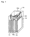
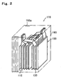
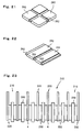
- Figs. 1 and 2 show the main parts of the unit cell 170 of the first capacitor.
- the cell container 160 of this unit cell 170 is provided with a bellows 160a as a stress relaxation structure to relax the stress generated by the expansion of polarizing electrodes (carbon material).
- the cell container is preferably fabricated from stainless steel, for example.
- the bellows 160a may be provided in the center of the cell container 160 as shown in Fig. 1, or at the end as shown in Fig. 2. It may also be provided to the entire cell container 160, though not illustrated. As the liquid level of the organic electrolytic solution is lowered when the bellows 160a is elongated, the length of the bellows 160a when completely elongated is determined so that the electrode members 110 may not be exposed out of the organic electrolytic solution.
- the construction of the unit cell 170, etc. are based on the unit cell 170 described above, except that the carbon material having partially oxidized graphite-like microcrystalline carbon described above is used. And the capacitance of the unit cell 170 is considered to be manifested by adsorption of ions to the electrochemical reaction products during the first charging.
- the electrode members 110 may be either based on the structure shown in Figs. 8 and 9 (B), or those obtained from carbon material, a binder such as polytetrafluoroethylene, and a conductance aid such as carbon black, applied onto the surfaces of collectors as a paste formed by mixing with a solvent, dried to remove the solvent by evaporation, and then held between separators 104.
- a binder such as polytetrafluoroethylene
- a conductance aid such as carbon black
- the first capacitor is obtained by connecting plurality of unit cells 170 with the construction described above in a series, and fabricate them as a nodule.
- the bellows 160a will not give fracture, and will not give fatigue fracture until the end of charging/discharging cycle life of the first capacitor. Particularly, the bellows 160a will not give fracture against the stress of 13.6 kgf/cm 3 (1.33 MPa), the highest value in Fig. 12, and is able to undergo over 100,000 elongation/contraction cycles.
- the electrochemical capacitor related to the second embodiment (called the second capacitor hereafter), and the cell container this second capacitor is provided with will be explained in reference Fig. 3 showing the main part of the unit cell 171.
- the cell container 161, the second capacitor is provided with, is provided with a flat spring 161a as a stress relaxing system.
- Electrode members 110 are contained in one of the two rooms, and a flat spring 161a is set in another room. Also, the flat spring 161a may be fixed to the sliding plate 161b, or held between the sliding plate 161b and the external wall of the cell container 161.
- the second capacitor may preferably be minimized by using a flat spring 161a with small spring modulus in the early stage when the difference is large, and changing springs to the one with large spring modulus when the difference has converged on a constant value.
- the stress caused by expansion of the polarizing electrodes 130 can thus be relaxed without elongating the cell container 161 itself, and therefore there is an advantage that the cell container itself does not change its size.
- the third capacitor the electrochemical capacitor related to the third embodiment
- the electrode members this third capacitor is provided with
- the collectors 120 are comprised of an elastic body as shown in the cross-sectional view in Fig. 4.
- the cross-sectional view shown in Fig. 4 seen from the same direction as in Fig. 10.
- the collectors 120 comprising of elastic body are held between the polarizing electrode sheets 130 having carbon material as their active substance, and further held between separators 104.
- the polarizing electrode sheets 130 are obtained by blending carbon material, a binder such as polytetrafluoroethylene, and a conduction aid such as carbon black, and then rolled.
- elastomers used as the collectors 120 those with collecting capability equal to the conventional collector material aluminum foil, etc. are used, and particularly porous conducting rubber sheet in which carbon black is dispersed or elastically deform able porous aluminum wool are preferable embodiments.
- the collectors 120 when the polarizing electrodes 130 expand to generate stress during charging, the collectors are pressurized, but as the collectors 120 are elastomers, strain easily occurs.
- the stress due to expansion of the electrode members 130 is relaxed by the occurrence of the strain, expansion of the electrode members 111 as a whole is reduced. As a result, plastic deformation of the cell container can be prevented.
- the collecting capability of the collectors 120 comprising of elastomers described above equals to that of the conventional collector material, aluminum foil, and therefore the third capacitor has a charging/discharging properties superior to those of conventional capacitors 108.
- the electrode members 112 the fourth capacitor is provided with has separators 140 constructed from elastomers.
- separators 140 constructed from elastomers.
- FIG. 5 the cross-section shown in Fig. 5 is seen from the same direction as in Figs. 4 and 10.
- these electrode members 112 are constructed by the collectors 102 held between the polarizing electrodes 130, and these being further held between separators 140 comprised of elastomers.
- insulating porous materials capable of electrically separating positive and negative poles and allowing electrolyte ions to penetrate through them are selected, insulating porous rubber, particularly porous fabric or nonwoven fabric of glass fiber, or cellulose nonwoven fabric being preferable.
- the fourth capacitor having the same construction as conventional capacitors 108 except for using such an elastomer as described above as the separators 140 and using polarizing electrodes 130, polarizing electrodes 130 expand during charging to generate stress pressurizing the separators 140, the separators 140 easily form strains they are elastomers. Thus, the stress due to expansion of the polarizing electrodes 130 is relaxed be strain formation, suppressing expansion of the electrode members 112 as a whole. This results in prevention of plastic deformation of the cell container.
- the elastomers described above have ion penetrating capacity equal to that of a blend paper, and therefore the fourth capacitor has charging/discharging properties equal to those of the third capacitor.
- the electrode members of the present embodiment may be those obtained from carbon material, a binder, and a conductance aid applied onto the surfaces of collectors of aluminum foil, etc. as a paste formed by mixing with a solvent, dried to remove the solvent by evaporation, and then held between separators 140 comprising of elastomers described above.
- the electrochemical capacitor related to the fifth embodiment (called the fifth capacitor) and the electrode members the fifth capacitor is provided with will be explained with reference to Fig. 6.
- the electrode members 113 the fifth capacitor is provided with has collectors 120 and separators 140 comprised of elastomers.
- the cross-sectional view shown in Fig. 6 is seen from the same direction as in Figs. 4, 5, and 10.
- these electrode members 113 are constructed by the collectors 120 held between the polarizing electrodes 130, and these being further held between separators 140 comprised of elastomers.
- the fifth capacitor having the same construction as conventional capacitors 108 except for being provided with such collectors 120 and separators 140, and using polarizing electrodes 130, the stress generated accompanying expansion of the polarizing electrodes 130 is relaxed by formation of strain both in the collectors 120 and in the separators 140.
- the fifth capacitor has charging/discharging properties equal to those of conventional capacitors 108, is superior to the third and fourth capacitors in the stress relaxing effects. Therefore it is suitable to the cases when greater stress is generated, for example in case greater number of electrode members are stacked.
- the electrode members of the present embodiment may be those obtained from carbon material, a binder, and a conductance aid applied onto the surfaces of collectors 120 as a paste formed by mixing with a solvent, dried to remove the solvent by evaporation, and then held between separators 140.
- the electrochemical capacitor related to the present invention may be provided at the same time with the cell container and one of the three electrode members described above.
- the electrochemical capacitor related to the sixth embodiment (called the sixth capacitor hereafter) will be explained with reference to Fig. 6.
- the unit cells 172 of the sixth capacitor has the same construction as that of the unit cells 107 of conventional capacitors 108, except for setting the stack 151 stacking the electrode members 113 shown in Fig. 6 in the cell container 160, as shown in Fig. 7.
- the sixth capacitor is obtained by stacking plurality of these unit cells 172 to fabricate a module.
- both the electrode members 113 and the cell container 160 can relax the stress.
- it is superior to the first and fifth capacitors in the stress relaxing effect. Therefore, the cell container 160 is free from plastic deformation, etc., and better charging/discharging property is obtainable than conventional capacitors 108.
- each of the first through sixth capacitors it is desirable to pressurize the electrode members by applying pressure in the direction of stacking of the stacks. This because the contact resistance between the collectors and the polarizing electrodes are reduced.
- Application of pressure may be realized, for example, by compressing the stack with suitable pressure in advance and putting them in a cell container whose volume is just enough to keep the compressed state.
- the pressure is preferably 2 kgf/cm 2 (196 kPa) or above. Therefore, when the flat spring is changed in the second capacitor as described above, it is preferable that spring modulus of the flat spring is enough to apply pressure of 2 kgf/cm 2 (196 kPa) or above to the stack.
- the polarizing electrodes and the separators located between the positive and negative poles may be impregnated with the organic electrolytic solution. Even such capacitors show capacitance and upper limited voltage equal to those of capacitors having stacks completely immersed in the oganic electrolytic solution.
- the state of polarizing electrodes being immersed in organic electrolytic solution shall include such a state of polarizing electrodes and separators being impregnated with organic electrolytic solution.
- the organic electrolytic solution with which separators are impregnated together with the electrolyte ions is also adsorbed to the carbon material during charging. This phenomenon especially significant during the first charging, but also occurs during later charging. Therefore, when conventional cellulose blend paper is use as the separator, the organic electrolytic solution will decrease as charging advances, and in some cases all the solution will be absorbed to cause so called drying-up, resulting in the inconvenience that charging of electrochemical capacitors become impossible.
- sponge-like porous insulators are used as separators in the electrochemical capacitors of the present invention. That is because sponge-like porous insulators can retain a lot of liquid inside. Also, that is because polarizing electrode layers will not go through separators. Further, that is because porous materials will not prevent ions from going through.
- the pair of electrodes 210 of the electrochemical capacitor of the present invention is constructed by combining a positive pole 220 and a negative pole 230 each fabricated by forming layers of polarizing electrodes 250 having as main components carbon material with partially oxidized graphite-like microcrystalline carbon on the collectors 4, as shown in Fig. 19.
- Layers of polarizing electrodes 250 are formed, for example, mixing and blending carbon material, a binder and an conduction aid to form a sheet, process it into a fixed form and area, and attach it to the collectors 4. Also they may be formed by coating the surface of the collectors 4 with a paste prepared by mixing carbon material, a binder and a conduction aid with a solvent, and dry them to remove the solvent by evaporation.
- separators 260 comprised of sponge-like porous insulator are located between the positive poles 220 and the negative poles 230.
- "Sponge-like” indicates here the property of materials capable of absorbing and holding large amount of liquid in which the material is immersed, and capable of elastic deformation.
- separators 260 are sponge-like, they may be impregnated with large amounts of organic electrolytic solutions such as ethylene carbonate, propylene carbonate, ⁇ -butyrolactone, sulfolane, etc. in which electrolytes such as Et 4 NBF 4 (Et 4 N; tetraethylammonium), Et 4 NPF 6 , Bu 4 NBF 4 (Bu 4 N: tetrabutylammonium) or Bu 4 NPF 6 are dissolved at a fixed concentration, for example, of 1 mol/l. Therefore, the inconvenience of shortage of organic electrolytic solutions will not occur during operation of the electrochemical capacitors, as described below. Needless to say, separators 260 must be impregnated with more organic electrolytic solutions than absorbed by the carbon material.
- organic electrolytic solutions such as ethylene carbonate, propylene carbonate, ⁇ -butyrolactone, sulfolane, etc.
- electrolytes such as Et 4 NBF 4 (Et 4 N; te
- separators 260 are highly elastic as they are sponge-like. Thus, they will easily deform themselves in case layers of polarizing electrodes 250 expand. Therefore, the layers of polarizing electrodes 250 will not go through separators 260.
- separators 260 materials that are sponge-like, porous insulators so that electrolyte ions can go through, and electrochemically inert are selected.
- materials that are sponge-like, porous insulators so that electrolyte ions can go through, and electrochemically inert are selected.
- glass fiber nonwoven fabric, and polymeric materials such as nylon are suitable. Fibers made of organic compounds may be used as a part of glass fiber nonwoven fabrics.
- the separators located between the positive poles 220 and the negative poles 230 are impregnated with, into the carbon material also occurs.
- the separators 260 are impregnated with a large amount of organic electrolytic solution, however, shortage of the organic electrolytic solution will not occur during operation of the electrochemical capacitor.
- the layers of polarizing electrodes 250 expand due to intake of the electrolyte ions by the carbon materials and absorption of the organic electrolytic solution by the carbon material during charging, the polarizing electrodes 250 will not go through the separators 260, and short circuit between the positive poles 220 and the negative poles 230 will not occur, as the sponge-like separators 260 easily deform themselves.
- separators 260 are porous insulator that can electrically insulate the positive poles 220 and the negative poles 230 while allowing the electrolyte ions to go through, they will not interfere with charging/discharging reaction of the electrochemical capacitor.
- the separators 260 are preferably provided with parts comprised of rigid materials, in order to prevent leakage of electrolytic solutions from the separators 260 in case the pairs of electrodes 210 are compressed by applying pressure in order to reduce the contact resistance between the collectors 4 and the polarizing electrodes 250.
- the separators 260 may be provided with frames 262 made of rigid material around their outer edges, as shown in Fig. 20. By providing these frames 262, the separators 260 will not be compressed below the thickness of the frames 262 when pressurized. Therefore, the electrolytic solution the separators 260 are impregnated with may not leak.
- the frames 262 are not limited to those surrounding the outer edges of the separators 260 as shown in Fig. 20, and may be provided for example in the form of crosses as shown in Fig. 21 or in both edges and in the center of the separators 260 as shown in Fig. 22.
- the materials for frames 262 are porous insulators of ceramics, plastics, etc. It is because internal resistance will not rise as those materials will not prevent migration of electrolyte ions. Also, the frames 262 may be formed by hardening parts of the separators 260.
- a stack 215 wherein plural pairs of electrodes 210 are stacked as shown in Fig. 23 may be used.
- layers of polarizing electrodes 250 may be formed on both side of collectors 4, and separators 260 may also be located between the pairs of electrodes 210.
- Petroleum cokes 100 g used as the organic material, was carbonized by heat treatment in an atmosphere of nitrogen at 800°C for 2 hours, and cooled to the room temperature. The rate of heating was 100° C/h. The carbon material obtained was then ground to mean particle size of 35 ⁇ m.
- This carbon material powder 50 g and potassium hydroxide 100 g were placed in an alumina crucible and alkaline activation treatment was carried out in an atmosphere of nitrogen at 800°C for 2 hours. After cooling, unnecessary potassium compounds such as potassium hydroxide were removed by water cleaning, and powdery carbon material was obtained by filtration and drying.
- Carbon black 0.1 g as the conduction aid and PTFE (polytetrafluoroethylene) as the binder were added for 1 g of the carbon material obtained, mixed, blended, and further rolled to form a 0.5 mm thick sheet.
- Disc with 19 mm ⁇ punched out of the electrode sheet thus obtained were used as the polarizing electrodes of the positive and negative poles, aluminum foil was used as the collectors, glass fiber nonwoven fabric was used as the separators, PC was used as the solvent, and methlethylpyrolidinium tetrafluoroborate (MEPYBF4) was used as the electrolyte to prepare electrolytic solution of concentration of 2 mol/l, to fabricate a capacitor (Embodiment 1) having structure equal to the single electrode cell 10 described in Fig. 15. As a case, one made of resin film was used in order to determine the surface pressure difference described below.
- tetraethylammonium tetrafluoroborate (TEABF4) was used as the electrolyte to prepare an electrolytic solution of concentration of 1 mol/l, to fabricate a capacitor (Embodiment 2) having structure equal to that of the single electrode cell 10 shown in Fig. 15.
- the three kinds of capacitors described above were charged up to 4 V at the initial current of 5 mA, and activated by constant voltage charging for 20 min, then charging/discharging test was carried out at 2 V, 2.5 V, 3 V, 3.5 V, and 4 V.
- the charging current was 10 mA and the discharging current was 5 mA for the test.
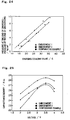
- Fig. 24 is a graph showing the relation between discharging coulomb quantity and pressure difference (surface pressure difference) of the end of charging and the end of discharging.
- the surface pressure difference was confirmed to be smaller with embodiments 1 and 2 than with comparative example.
- surface pressure difference was determined using an determination apparatus 51 having a pressure sensor 53 such as a strain gauge located on the base 52, the lower mold 54 located on the pressure sensor 53, and the upper mold 57 capable positioning and fixing with a screw 59, holding the various capacitors prepared 56 (using resin film as the case) between the lower mold 54 and the upper mold 57, and following the pressure difference accompanying charging/discharging of capacitors 56 by reading the indication of the pressure sensor 53.
- the lower mold 54 and the upper mold 57 are freely movable perpendicularly by way of a linear bush 55.
- Fig. 25 is a graph showing the relation between the capacitance density of embodiments 1, 2 and the comparative example and voltage.
- the case material and the shape of the case are not considered, and therefore this capacitance density indicates capacitance density of single electrode cells only.
- improvement of capacitance density of single electrode cells were confirmed to be realized.
- Petroleum cokes was heat treated in an atmosphere of nitrogen at 800°C for 2 hours to obtain a carbonized substance. After grinding to mean particle size of 40 ⁇ m, the carbonized substance was mixed with KOH in the ratio of 1:2 (by weight, same hereafter). This mixture was heat treated in an atmosphere of nitrogen at 800°C for 2 hours, and then washed with water and dried to obtain a carbon material with graphite-like microcrystalline carbon.
- the obtained carbon material, acetylene black (conduction aid), and polytetrafluoroethylene (binder) are mixed in the ratio of 10:1:1, and blended to give a sheet of thickness of 0.5 mm thickness. Discs with diameter of 19 mm punched out from the sheet were used as polarizing electrodes 250.
- the positive pole 220 and the negative pole 230 were prepared by attaching said polarizing electrode 250 to the collectors 4 comprised of aluminum, and they were combined to prepare a pair of electrodes 210.
- a separator 260 made of borosilicate glass fiber with 440 ⁇ m thickness and 0.25 g/cm 3 density, impregnated in advance with 2 cc organic electrolytic solution of 1 mol/l of Et 4 NBF 4 dissolved in propylenene carbonate was located between the positive pole 220 and the negative pole 230, as shown in Fig. 19. Further, the amount of liquid retention per unit area of this separator 260 was 0.58 cc/cm 2 .
- Embodiment 3 an electrochemical capacitor having them was fabricated at last.
- This electrochemical capacitor will be called Embodiment 3 hereafter.
- This electrochemical capacitor will be called the comparative example 2.
- Charging/discharging cycle was carried out on the embodiment 3 and the comparative example 2. Particularly, a cycle of constant current charging at 10 mA (up to 4 V) and constant current discharging at 5 mA was repeated.
- the third cycle charging/discharging voltage curves of the embodiment 3 and the comparative example 2 are shown in Fig. 27.
- the solid line represents embodiment 3
- the dotted line represents the comparative example 2. From Fig. 27 it is understood that the voltage rapidly rose during charging stopping charging in the comparative example, and charging continued at that stage in the embodiment 3.
- volume change accompanying charging/discharging of polarizing electrodes and the pressure due to the volume change may be reduced, significant effects are obtained including increase in freedom of selection of material for cases and designing the case thickness, increase in capacitance density and weight density of capacitance, and improvement of reliability and lengthening of life.
- the present invention has the effect of increasing in capacitance of the single electrode itself excluding the case.
- electrochemical capacitors showing capacitance and upper limited voltage that surpass those of electric double layer capacitors utilizing conventional activated carbons.
- An electrochemical capacitor wherein electrode members composed of polarizing electrodes, whose main ingredient is a carbon material having partially oxidized graphite-like microcrystalline carbon, separators, and collectors is immersed in a organic electrolytic solution, said polarizing electrodes expanding on charging and contracting on discharging. Ions with ionic radii of 0.33 nm or less are used as the electrolyte cations of the organic electrolytic solution.
- the cell container holding electrode members and the electrolytic solution is provided with stress relaxing structure. Either collectors or separators are elastomers.
- the separators are sponge-like porous insulator with continuous pores.
Landscapes
- Engineering & Computer Science (AREA)
- Power Engineering (AREA)
- Microelectronics & Electronic Packaging (AREA)
- Chemical & Material Sciences (AREA)
- Chemical Kinetics & Catalysis (AREA)
- Electrochemistry (AREA)
- Electric Double-Layer Capacitors Or The Like (AREA)
Abstract
An electrochemical capacitor wherein electrode members composed of
polarizing electrodes, whose main ingredient is a carbon material having
partially oxidized graphite-like microcrystalline carbon, separators, and
collectors is immersed in a organic electrolytic solution, said polarizing
electrodes expanding on charging and contracting on discharging. Ions
with ionic radii of 0.33 nm or less are used as the electrolyte cations of the
organic electrolytic solution. The cell container holding electrode
members and the electrolytic solution is provided with stress relaxing
structure. Either collectors or separators are elastomers. The
separators are sponge-like porous insulator with continuous pores.
Description
- The present invention relates to electrochemical capacitors wherein reliability and durability are improved by reducing the pressure generated by change in volume accompanying charging and discharging, when high-performance carbon materials with large electrostatic capacity are used as polarizing electrodes. The present invention also relates to electrostatic capacitors having structures relaxing the stress generated by expansion of the polarizing electrodes on charging.
- Besides being used as back-up power sources and batteries for transportation vehicles from automobiles down, as they have large capacity of the Farad class and are excellent in charging and discharging cycle characteristics, electric double layer capacitors, a type of capacitors, are investigated to use for the purpose of off-peak power storage from the view point of effective utilization of energy.
- A
single electrode cell 10, one of the basic structures of such electric double layer capacitors, has the structure as shown in Fig. 15 in which a positiveside polarizing electrode 24 and a negativeside polarizing electrode 26 are respectively formed oncollectors electrodes separator 28, and are impregnated with electrolytic solution comprising the solvent and electrolytes. - Fig. 16 shows the structure of a
single capacitor cell 12, wherein plurality ofsingle electrode cells 10 are electrically connected parallel with each other toelectrode outlet parts collectors single capacitor cell 12 is suitably used as an electric double layer capacitor with relatively large capacity used for automobiles, etc. Bothsingle electrode cells 10 orsingle capacitor cells 12 are planar and characterized by easiness of tight packing and expansion. - In contrast to such planar electric double layer capacitors, there are also coil type electric
double layer capacitors 70 having structures suitable for capacity enlargement similarly tosingle capacitor cell 12 as shown in Fig. 17. A coil type electricdouble layer capacitor 70 is prepared using acoil 76 prepared by cylindrically coiling apositive electrode sheet 72, in which a positive electrodeside polarizing electrode 24 is formed on acollector 20, and anegative electrode sheet 74, in which a negative poleside polarizing electrode 26 is formed on acollector 22, with aseparator 28 between them, and for example by puttingsaid coil 76 in acase 78 and fill the case with electrolytic solution, and sealing the opening end surface of thecase 78 with asealing plate 82 having anelectrode terminal 80 formed on it, while securing continuity betweenelectrode sheets electrode terminal 80. - As polarizing electrode materials for such electric double layer capacitors, those having activated carbon with relative surface area of 1000 m2 or more as a main ingredient have traditionally been used. The construction of a pair of electrode of an electric double layer capacitor using such activated carbons will be explained referring to Fig. 18.
- As shown in Fig. 18, this pair of
electrodes 1 is constructed to have apositive pole 2 and anegative pole 3 stuck to one another with aseparator 6 between them. - To explain more precisely about the
positive pole 2 and thenegative pole 3, they have layers of polarizingelectrodes 5 containing activated carbon as an essential ingredient and optionally binders such as polytetrafluoroethylene and conduction aids such as carbon black, on the surface of acollector 4 comprising aluminum foil, etc. - Further, the layer of polarizing
electrode 5 is formed for example by blending a mixture of fixed ratio of activated carbon, a binder and a conduction aid to give a sheet of fixed shape and area, which is then adhered onto acollector 4. It may also be formed by coating the surface of acollector 4 with a paste of a mixture of activated carbon, a binder, a conduction aid, and a solvent and drying it to remove the solvent by evaporation. Known coating methods such as spray coating and brush coating may be adopted. - Here the
separator 6 is impregnated with an organic electrolytic solution (not shown) such as ethylene carbonate, propylene carbonate, γ-butyrolactone, and sulfolane, containing a fixed concentration, for example, of 1 mol/l of an electrolyte such as Et4NBF4 (Et4N; tetraethylammonium), Et4NPF6, Bu4NBF4 (Bu4N: tetrabutylammonium) or Bu4NPF6. - When such an electric double layer capacitor having a pair of
electrodes 1 and aseparator 6 is charged, the ions of the electrolyte are adsorbed inside micropores of the activated carbon which is the essential ingredient of the polarizing electrode, and this adsorption causes capacitance to occur in the electric double layer capacitor. - As the
separator 6, ones that may electrically insulate thepositive pole 2 and thenegative pole 3 to prevent them to short, and may allow ions of the electrolytes to penetrate so that ions of the electrolytes can migrate toward the positive pole and thenegative pole 3 during charging and discharging. Cellulose blend paper is particularly suitable. Cellulose blend paper also has advantages that it is inexpensive enabling cost reduction, and may be formed thinner enabling reduction of internal resistance of the electric double layer capacitor. - Further, cellulose blend paper will not melt even when the positive and negative electrodes shorts, as it has high melting point. Therefore, it is seldom used as electric cell separators. This is because migration of electrolyte ions is not prevented, as ion penetrating pores of the separator is not blocked even when internal temperature of an electric cell rises due to excessive reaction of the cell when elctrodes short, resulting in further rise of the internal temperature.
- Internal temperature of an electric double layer capacitor, however, scarcely rises even when the separator does not melt in short circuit. In other words, there is no problem in using high melting point separators, since internal temperature would not rise significantly in short circuit. These and the advantages described above are the reason why cellulose blend paper is widely used.
- Capacitance and upper limited voltage of conventional electric double layer capacitors described above depend on the activation method of activated carbon. For example, capacitance is 15 F/cc and upper limited voltage is 3 V for an electrochemical capacitor using steam-activated carbons, and capacitance is 20 F/cc and upper limited voltage is 2.5 V for an electrochemical capacitor using alkali-activated carbons.
- Capacitance and upper limited voltage of various capacitors including electrical double layer capacitors are expected recently to improve further, those with these values above 30 F/cc and 3.5 V being desired.
- Thus, alkali-activated new polarizing electrode materials are reported in Japanese patent provisional publications No. 275042/1997 and 320906/1997 in order to increase the capacity of polarizing electrode materials.
- In case of electrochemical capacitors using alkali-activated polarizing electrode materials as disclosed in Japanese patent provisional publications No. 275042/1997 and 320906/1997, however, there is a problem of volume expansion of the polarizing electrode materials due to charging. There was no such problems of volume expansion in electric double layer capacitors using conventional activated carbons.
- This volume expansion tends to increase as the amount of electricity contributing to charging and discharging, and is especially a big problem in uses wherein it is preferable that capacitance is big, charging and discharging capacity is big, and further capacitance density (density of capacitance for unit volume) or capacitance weight-density (density of capacitance for unit weight) is big, especially as in automobiles.
- For example, in electrochemical capacitors using
single capacitor cells 12 described above,single capacitor cells 12 are tightly packed in a capacitor case (to be called "case" hereafter) with least opening in order to make the capacitance density as large as possible. Hereelectrode outlets single electrode cells 10 constructingsingle capacitor cells 12,separators 28 are designed to have areas larger than those of polarizingelectrodes electrodes electrodes - In the direction of stacking of
single electrode cells 10 insingle capacitor cells 12, however, the surface pressure occurred from volume expansion of polarizingelectrodes single electrode cell 10 sums up to significant amount of pressure, possibly causing deformation or destruction of the case and damage or deterioration ofcollectors separators 28, eventually even inducing deterioration of the cycle characteristics. Though it is possible here to deal with the surface pressure by employing stronger or thicker materials for the case, this may cause reduction of capacitance density or weight density of capacitance. - On the other hand, when holding pressure between internal walls of the case and single capacitor cells is reduced to lessen the surface pressure due to such volume expansion, the
single capacitor cells 12 may not be held stably in the case causing problems of increased internal resistance and greater deviation of capacitance, that would reduce stability of properties. Such problems would be especially greater under circumstances where there is constant vibration as in the case of being installed in automobiles. - As coil-type electric
double layer capacitors 70 can be considered to have structures wherein polarizing electrodes are stacked in the direction of the core, the problem of volume expansion of polarizing electrodes in the electrochemical capacitors having a coil-type structure may be considered in the same manner as in the case ofsingle capacitor cells 12. Thus, in coil-type electrochemical capacitors, surface pressure is applied onto the cylindrical wall of the case, that would cause deformation or destruction of the case with greater possibility. - The present invention was made in view of the problems of conventional technology described above, with the purpose of providing electrochemical capacitors in which reduction of occurring surface pressure is enabled without reducing capacitance by paying attention to electrolytes of organic electrolytic solutions used in electrochemical capacitors.
- Another purpose of the present invention is to provide electrolytic capacitors showing capacitance and upper limited voltage that are superior to those of electric double layer capacitors using activated carbon.
- Thus, according to the present invention, there is provided an electrochemical capacitor comprising:
- polarizing electrodes, whose main ingredient is a carbon material having partially oxidized graphite-like microcrystalline carbon, and
- an organic electrolytic solution,
said polarizing electrodes being immersed in the organic electrolytic solution, and said polarizing electrodes expanding on charging and contracting on discharging,
wherein ions with radius of ions of 0.33 nm or less are used as electrolyte cations of said organic electrolytic solution. -
- In such electrochemical capacitors of the present invention, it is preferable to use trimethylammonium ion or methylethylpyrrolidinium ion as the cation.
- Also, according to the present invention, there is provided an electrochemical capacitor comprising:
- electrode members comprised of polarizing electrodes, whose main ingredient is a carbon material having partially oxidized graphite-like microcrystalline carbon, separators, and collectors,
- an organic electrolytic solution, and
- a cell container containing the electrode members and the
organic electrolytic solution,
said electroe members being immersed in the organic electrolytic solution, and said polarizing electrodes expanding on charging and contracting on discharging,
wherein said electrode members and said cell container are provided with stress relaxing structure. -
- As stress relaxing structures suitably employed in the electrochemical capacitors of the present invention, there are bellows and flat spring types. Further, it is also preferable to use an elastomer for either the collector or the separator.
- According to the present invention, there is further provided an electrochemical capacitor comprising:
- electrode members comprised of polarizing electrodes, whose main ingredient is a carbon material having partially oxidized graphite-like microcrystalline carbon, separators, and collectors, and
- an organic electrolytic solution,
said electrode members being immersed in the organic electrolytic solution, and said polarizing electrodes expanding on charging and contracting on discharging,
wherein at least either said collectors or said separators is an elastomer. -
- It is preferable to use elastically deformable porous conductive rubber sheets or porous aluminum sheets as collectors for this electrochemical capacitors.
- In the electrochemical capacitor described above, it is preferable to use an elastically deformable insulating porous body as the separator, and one out of porous rubber, porous cloth or nonwoven fabric of glass fiber, and cellulose nonwoven fabric as the insulating porous body. Also, the electrode structure is preferably in the oppressed condition under the pressure of 2 kgf/cm2 (196 kPa) or more.
- Plastic deformation of the cell containers will not occur in these electrochemical capacitors of the present invention, as generated stress is relaxed by the cell containers or the electrode structures.
- According to the present invention, there is still further provided an electrochemical capacitor comprising:
- polarizing electrodes, whose main ingredient is a carbon material having partially oxidized graphite-like microcrystalline carbon,
- separators, and
- an organic electrolytic solution,
said polarizing electrodes and said separators being immersed in the organic electrolytic solution, and said polarizing electrodes expanding on charging and contracting on discharging,
wherein said separators are a sponge-like porous insulator with continuous pores. -
- In such electrochemical capacitors, cloth or nonwoven fabric having at least inorganic fibers is preferably used as the porous insulators. It is also preferable to use polymeric materials as the porous insulators.
- The electrochemical capacitors will not run short of organic electrolytic solution by using, as the separators, sponge-like materials that can be impregnated with large amounts of organic electrolytic solution. Further, as these separators are easily deformable, polarizing electrodes will not go through the separators even when expanded. Thus, the positive and negative poles may not short.
-
- Fig. 1 is a perspective view illustrating an embodiment of the construction of an electrochemical capacitor (unit cell) relating the present invention.
- Fig. 2 is a perspective view illustrating another embodiment of the construction of an electrochemical capacitor (unit cell) relating the present invention.
- Fig. 3 is a perspective view illustrating still another embodiment of the construction of an electrochemical capacitor (unit cell) relating the present invention.
- Fig. 4 is a cross-sectional view illustrating an embodiment of the electrode structure an electrolytic capacitor of the present invention is provided with.
- Fig. 5 is a cross-sectional view illustrating another embodiment of the electrode structure an electrolytic capacitor of the present invention is provided with.
- Fig. 6 is a cross-sectional view illustrating still another embodiment of the electrode structure an electrolytic capacitor of the present invention is provided with.
- Fig. 7 is a perspective view illustrating still another embodiment of the construction of an electrochemical capacitor (unit cell) relating the present invention.
- Fig. 8 is a perspective view illustrating an embodiment of the construction of a conventional electrochemical capacitor (unit cell).
- Fig. 9 (A), (B) are perspective views illustrating embodiments of the electrode structures electrolytic capacitors of the present invention are provided with.
- Fig. 10 is a cross-sectional view of Fig. 9 (B) viewed from A-A.
- Fig. 11 is a perspective view illustrating prepared state of an electrochemical capacitor module combining unit cells shown in Fig. 8.
- Fig. 12 is a graph showing the values of stress generated and remained during charging and discharging cycles of an electrochemical capacitor of the present invention.
- Fig. 13 (A), (B) schematically illustrate microstructures of carbon materials preferably utilized in electrochemical capacitors of the present invention.
- Fig. 14 schematically illustrates the molecular structure of microcrystalline carbon in the carbon material preferable used in the electrochemical capacitor of the present invention.
- Fig. 15 is a perspective view of an embodiment of the structure of a single electrode cell.
- Fig. 16 is a perspective view of an embodiment of the structure of a single capacitor cell.
- Fig. 17 is a perspective view of an embodiment of the structure of a coil-type capacitor.
- Fig. 18 illustrates an embodiment of the electrode pair construction a conventional electrochemical double layer capacitor is provided with.
- Fig. 19 illustrates an embodiment of the electrode pair construction the electrochemical double layer capacitor of the present invention is provided with.
- Fig. 20 is a perspective view showing the state wherein a frame surrounding the outer edges of a separator is provided.
- Fig. 21 is a perspective view showing the state wherein a separator is provided with cross-shaped frames.
- Fig. 22 is a perspective view showing the state wherein a separator is provided with frames at both edges and in the center.
- Fig. 23 illustrates an embodiment of a stack construction wherein plural of electrode pairs the electrochemical capacitor of the present invention is provided with are stacked.
- Fig. 24 is a graph showing relation between the surface pressure generated on electrochemical capacitors and the discharge coulomb value of an embodiment and a comparative example.
- Fig. 25 is a graph showing relation between the capacitance volume density applied to electrochemical capacitors and the voltage of an embodiment and a comparative example.
- Fig. 26 is a schematic cross-sectional view of the structure of an apparatus for determining surface pressure generated by volume expansion of the electrochemical capacitor.
- Fig. 27 is a graph showing the third cycle charging and discharging
voltage curves of an
embodiment 3 and comparative example 2. -
- Electrochemical capacitors of the present invention have polarizing electrodes comprising as the main ingredient carbon materials having partially oxidized graphite-like microcrystalline carbon, impregnated with an organic electrolytic solution, said polarizing electrodes being characterized by volume expansion on charging and volume contraction on discharging. First the carbon materials will be explained below.
- Organic materials such as petroleum cokes, coal cokes, petroleum pitch (tar), coal pitch (tar), phenolic resins, meso phase carbon, polyvinyl chloride, polyvinylidene chloride, polyimide, palm shell, and saw dust are first thermally treated in an inert circumstance, around the temperature range of about 700-1000°C to obtain the carbon material. Either one kind of organic material alone or a mixture of plurality of organic materials may be used. Nitrogen or rare gases such as argon and helium may be suitably used.
- Next, the carbon material obtained above is preferably ground to have fixed particle size. Grinding is not necessary, here, in case the carbon material is obtained in a form of powder, for instance as the organic material is in the form of powder. Uniformity in the partial oxidation reaction and reduction of the time for oxidation may be realized by this grinding. Various known methods of either dry or wet grinding may be used.
- Next, carbon materials having graphite-like microcrystalline carbon can be obtained by partial oxidation of the powdery carbon materials obtained above. As the methods of partial oxidation, here, besides heat treatment with oxidative gases such as air and oxygen, and chemical oxidation methods using for example hot nitric acid, oxidation methods by thermally treating the organic materials in the presence of at least one kind of alkali metal compound (to be called "alkali metals" hereafter) containing alkali metal and oxygen atoms below carbonation temperature of the organic materials in an inert gas atmosphere.
- Potassium, sodium, and lithium are suitably used as the alkali metal elements, and hydroxides such as potassium hydroxide and sodium hydroxide and carbonates such as potassium carbonate and sodium carbonate are suitably used as the oxygen-containing compounds of alkali metals. These alkali metals and their compounds may be used as mixtures of two or more kinds. Carbonized materials are thermally treated together with at least one alkali metal or alkali metal compound below decomposition temperature of organic materials in an inert gas atmosphere, and then washed with alcoholic solvents such as methanol and ethanol or distilled water, and filtered to obtain the carbon materials used for polarizing electrodes.
- Next, "partially oxidized graphite-like microcrystalline carbon" will be explained together with the structure of carbon materials. When various organic raw materials are carbonized at 1000°C or less, carbon of
random layer structure microcrystalline carbon 95 of 0.1 nm - tens nm among this carbon of randomlayered structure - Carbon of random
layered structure 90 of Fig. 13 (A) has a structure wherein carbon microcrystals 95 are stack at irregular angles with each other, with their layer planes oriented nearly parallel but not completely parallel. Such carbon of randomlayered structure 90 is found often in case organic materials easily converted to graphite during the carbonization process. - On the other hand, carbon of random
layered structure 91 of Fig. 13(B) has a structure wherein carbon microcrystals 95 are randomly oriented in network forms, often found in case organic materials difficultly turned to graphite during the carbonization process. - When these carbons of random
layered structure parts 97 with less regularity as crystals are first oxidized and evaporated as carbon monoxide and dioxide. As oxidation advances, edges of carbon microcrystals 95 themselves and parts with incomplete six member ring structure are oxidized, and finally all the carbon is oxidized into gases. - By controlling the oxidation condition, however, partial oxidation can be realized, resulting in "partially oxidized graphite-like microcrystalline carbon." In this carbon material, mainly acidic functional groups are bound to edges and regions with imperfect structure of six membered ring networks of the microcrystals, as shown in Fig. 14. It goes without saying that Fig. 14 schematically illustrates a form of molecular structure of the carbon material, and that it does not mean that the carbon materials of the present invention are limited to those with the structure of Fig. 14.
- Polarizing electrode are now prepared with the carbon materials described above as the main ingredient. Preparation of this polarizing electrode is carried out by adding organic binder and conduction aids such as carbon black to the carbon material, mixing and blending them, and processing the product into various forms such as plates and sheets.
- The carbon materials can be used as materials for polarizing electrodes regardless of capacitor structures, and capacitors with various structures are produced, for example, by putting the polarizing electrodes in the cases as
single electrode cells 10 shown in Fig. 15, andsingle capacitor cells 12 shown in Fig. 16, and further as structures such as coil-type capacitors shown in Fig. 17, impregnating them with organic electrolytic solutions. - The electrochemical capacitors related to the first aspect of the present invention will be explained next.
- In the first aspect of the present invention, organic electrolytic solutions for these capacitors containing electrolyte cations with ionic radii of 0.33 nm or less are used. In other words, the capacitors of the present invention are those in which solutes comprising ions with positive charges, namely cations, with ionic radii of 0.33 nm or less when the solute is dissolved in the organic electrolytic solution and exist as ions.
- This ionic radii was decided using the ionic radius (0.343 nm) of tetraethylammonium, conventionally used as a standard electrolyte, as the standard reference. Thus, in comparison with cases using conventional technology utilizing electrolytes comprising tetraethylammonium, freedom of selection of case materials and design of case thickness is increased, increase in capacitance density and weight density of capacitance are realized, and improvement of reliability and long life are realized, by reducing volume change of the polarizing electrodes accompanying charging and discharging and the pressure due to the volume change. Particularly, embodiments of ions with such ionic radii are trimethylethylammonium ions (ionic radii: 0.319 nm) and methylethylpyrrolidinium (ionic radii: 0.327 nm).
- As anions for such cations, tetrafluoroborate ionand hexafluorophosphate ion
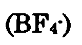 are suitable selected. Thus, BF4 salts or PF6 salts of trimethyammonium or methlethylpyrrolidinium are suitably used.
- As solvents for electrolytic solutions, those containing at least one of propylene carbonate (PC), γ-butyrolactone (GBL), ethylene carbonate (EC), sulfolane (SL) are suitably used. Also, it is possible to use those comprising at least one of said PC, GBL, EC, and SL as main solvents, and those comprising at least one of dimethyl carbonate (DMC), ethylmethyl carbonate (EMC), and diethyl carbonate (DEC) as auxiliary solvents.
- Here, the main solvent means a solvent that can serve sufficiently as an electrolytic solvent even alone, and the auxiliary solvent means a solvent that alone may serve poorly as an electrolytic solvent, but its combination with a main solvent can serve better than the main solvent or the auxiliary solvent alone, and there is no limitation in the amount of the auxiliary solvent such as less than 50%.
- Next, electrochemical capacitors relating to the second aspect of the present solvent will be explained.
- The single cell and the electrode member of a electric double layer capacitor (will be called a "conventional capacitor" below) using conventional activated carbon will be explained first with reference to Figs. 8-10.
- A
single cell 107 of the conventional capacitor is shown in Fig. 8. Thissingle cell 107, put in acell container 106, is astack 105 formed by alternatingly stacking plurality ofelectrode members 101, shown in Fig. 9 (A), Fig. 9 (B), and Fig. 10, that serve as positive and negative poles, and then bundlingoutlets 102a of each electrodes. - An organic electrolytic solution (not shown) of a solute such as Et4NBF4 (Et4N; tetraethylammonium), Et4NPF6, Bu4NBF4 (Bu4N: tetrabutylammonium), or Bu4NPF6, dissolved at a fixed concentration of for example about 1 mol/l in ethylene carbonate, propylene carbonate, γ-butyrolactone, or sulfolane (SL), is put in a
cell container 106, in which thestack 105 is immersed. And aunit cell 107 is constructed by electrically connecting the bundledelectrode outlets 102a to the positive terminal (not shown) or the negative terminal (not shown) fixed on top of thecell container 106. The electrode member connected to the positive terminal serves as a positive pole, and the electrode member connected to the negative terminal serves as a negative pole. - The
electrode members 101 are constructed as shown in Fig. 9 (A), whereincollectors 102 havingelectrode outlets 102a are held between sheets ofpolarizing electrodes 103, and the products are further held betweenseparators 104 as shown in Fig. 9 (B). Aluminum foil and a blend paper, processed into determined shapes, may be used ascollectors 102 andseparators 104 respectively. - Thus, cross-sectional view of Fig. 9 (B) indicated by arrows at A-A may appear as shown in Fig. 10. The sheets of
polarizing electrodes 103 can be obtained by blending activated carbon, binders such as polytetrafluoroethylene, and conduction aids such as carbon black together, and rolling the product. - Another embodiment of electrode members is those obtained by coating the surfaces of collectors with a paste of a mixture of activated carbon, a binder, a conduction aid, and a solvent, dried to remove the solvent, and held between separators (not illustrated).
- The conventional
flat capacitor 108 shown in Fig. 11 comprises plurality of theseunit cells 107 connected in a series constructing a module. - In comparison with such
conventional capacitors 8, the present invention proposes an electrochemical capacitor using polarizing electrodes comprising as an essential ingredient carbon material containing partially oxidized graphite-like microcrystalline carbon. In the electrochemical capacitor of the present invention, capacitance is considered to be manifested by adsorption of ions to the electrochemical reaction products formed during the first charging, and the capacitance is shown to be 30 F/cc and the upper limited voltage 3.5 V, both properties being superior to those ofconventional capacitors 108. - When such an electrochemical capacitor is charged by applying external voltage, the polarizing electrodes will expand to the direction of the electric field. This expansion is considered to be caused by the expansion of electrochemical reaction products formed during the first charging, reaching as much as twice the original volume in some cases.
- Such expansion of the polarizing electrodes during charging causes the expansion of electrode members and thus the stack. This will result in stress that eventually generates pressure against the container. Fig. 12 shows the maximum stress generated during each of charging/discharging cycle (called the maximum stress value hereafter), and the stress value remaining at the end of charging (called the residual stress hereafter).
- For the reasons described above, such inconveniences as plastic deformation of the cell containers have occurred in electrochemical capacitors of the construction mentioned above.
- Therefore, the present inventors devoted themselves in finding the means to relax the stress caused by this expansion of polarizing electrodes and reached the present invention. Embodiments relating to the present invention will be precisely explained below in reference to Figs. 1-7. Embodiments corresponding to Figs. 8-10 are given the symbols and explanation are omitted.
- First, explanation of the electrochemical capacitor relating to the first embodiment (called the first capacitor hereafter) and the cell container the first capacitor is provided with will be given.
- Figs. 1 and 2 show the main parts of the
unit cell 170 of the first capacitor. - The
cell container 160 of thisunit cell 170 is provided with abellows 160a as a stress relaxation structure to relax the stress generated by the expansion of polarizing electrodes (carbon material). The cell container is preferably fabricated from stainless steel, for example. - The
bellows 160a may be provided in the center of thecell container 160 as shown in Fig. 1, or at the end as shown in Fig. 2. It may also be provided to theentire cell container 160, though not illustrated. As the liquid level of the organic electrolytic solution is lowered when thebellows 160a is elongated, the length of thebellows 160a when completely elongated is determined so that theelectrode members 110 may not be exposed out of the organic electrolytic solution. - The construction of the
unit cell 170, etc. are based on theunit cell 170 described above, except that the carbon material having partially oxidized graphite-like microcrystalline carbon described above is used. And the capacitance of theunit cell 170 is considered to be manifested by adsorption of ions to the electrochemical reaction products during the first charging. - The
electrode members 110 may be either based on the structure shown in Figs. 8 and 9 (B), or those obtained from carbon material, a binder such as polytetrafluoroethylene, and a conductance aid such as carbon black, applied onto the surfaces of collectors as a paste formed by mixing with a solvent, dried to remove the solvent by evaporation, and then held betweenseparators 104. - The first capacitor is obtained by connecting plurality of
unit cells 170 with the construction described above in a series, and fabricate them as a nodule. - In this first capacitor, when the
polarizing electrodes 130 expands during charging, namely when thewhole stack 150 expands to generate stress, thebellows 160a is elongated. As the stress is relaxed by this elongation, deformation does not occur except for thecell container 160 and thebellows 160a. - And as
polarizing electrodes 130 are still immersed in the organic electrolytic solution even when thebellows 160a is completely elongated, charging and discharging properties superior toconventional capacitors 108. - It is needless to say that the
bellows 160a will not give fracture, and will not give fatigue fracture until the end of charging/discharging cycle life of the first capacitor. Particularly, thebellows 160a will not give fracture against the stress of 13.6 kgf/cm3 (1.33 MPa), the highest value in Fig. 12, and is able to undergo over 100,000 elongation/contraction cycles. - Next, the electrochemical capacitor related to the second embodiment (called the second capacitor hereafter), and the cell container this second capacitor is provided with will be explained in reference Fig. 3 showing the main part of the
unit cell 171. - The
cell container 161, the second capacitor is provided with, is provided with aflat spring 161a as a stress relaxing system. - Inside of this
cell container 161 is divide into two rooms by a slidingplate 161b moving inside saidcell container 161.Electrode members 110 are contained in one of the two rooms, and aflat spring 161a is set in another room. Also, theflat spring 161a may be fixed to the slidingplate 161b, or held between the slidingplate 161b and the external wall of thecell container 161. - When the
polarizing electrodes 130 are expanded by charging, the slidingplate 161b moves to the left in Fig. 3, and the flat spring is contracted. Thus, the stress generated accompanying expansion of thepolarizing electrodes 130 is relaxed. - Here, as shown in Fig. 12, difference between the maxumum stress value and the residual stress value converges on a constant value as the charging/discharging cycle advances. Therefore, the second capacitor may preferably be minimized by using a
flat spring 161a with small spring modulus in the early stage when the difference is large, and changing springs to the one with large spring modulus when the difference has converged on a constant value. - In the second capacitor the stress caused by expansion of the
polarizing electrodes 130 can thus be relaxed without elongating thecell container 161 itself, and therefore there is an advantage that the cell container itself does not change its size. - Next, the electrochemical capacitor related to the third embodiment (called the third capacitor hereafter), and the electrode members this third capacitor is provided with will be explained in reference to Fig. 4.
- In the
electrode members 111 the third capacitor is provided with, thecollectors 120 are comprised of an elastic body as shown in the cross-sectional view in Fig. 4. Here, the cross-sectional view shown in Fig. 4 seen from the same direction as in Fig. 10. - Thus, in this
electrode members 111, thecollectors 120 comprising of elastic body are held between thepolarizing electrode sheets 130 having carbon material as their active substance, and further held betweenseparators 104. Here, thepolarizing electrode sheets 130 are obtained by blending carbon material, a binder such as polytetrafluoroethylene, and a conduction aid such as carbon black, and then rolled. - As elastomers used as the
collectors 120, those with collecting capability equal to the conventional collector material aluminum foil, etc. are used, and particularly porous conducting rubber sheet in which carbon black is dispersed or elastically deform able porous aluminum wool are preferable embodiments. - In the third capacitor having the same construction as the
conventional capacitor 108 except for using elastomers described above as thecollectors 120 and usingpolarizing electrodes 130, when thepolarizing electrodes 130 expand to generate stress during charging, the collectors are pressurized, but as thecollectors 120 are elastomers, strain easily occurs. Thus, as the stress due to expansion of theelectrode members 130 is relaxed by the occurrence of the strain, expansion of theelectrode members 111 as a whole is reduced. As a result, plastic deformation of the cell container can be prevented. - The collecting capability of the
collectors 120 comprising of elastomers described above equals to that of the conventional collector material, aluminum foil, and therefore the third capacitor has a charging/discharging properties superior to those ofconventional capacitors 108. - Next, the electrochemical capacitor elected to the fourth embodiment (called the fourth capacitor hereafter) and the electrode members this capacitor is provided with will be explained with reference to Fig.5.
- The
electrode members 112 the fourth capacitor is provided with hasseparators 140 constructed from elastomers. Here the cross-section shown in Fig. 5 is seen from the same direction as in Figs. 4 and 10. - Thus, these
electrode members 112 are constructed by thecollectors 102 held between thepolarizing electrodes 130, and these being further held betweenseparators 140 comprised of elastomers. - As elastomers used for the
separators 140, insulating porous materials capable of electrically separating positive and negative poles and allowing electrolyte ions to penetrate through them are selected, insulating porous rubber, particularly porous fabric or nonwoven fabric of glass fiber, or cellulose nonwoven fabric being preferable. - Although in the fourth capacitor, having the same construction as
conventional capacitors 108 except for using such an elastomer as described above as theseparators 140 and usingpolarizing electrodes 130,polarizing electrodes 130 expand during charging to generate stress pressurizing theseparators 140, theseparators 140 easily form strains they are elastomers. Thus, the stress due to expansion of thepolarizing electrodes 130 is relaxed be strain formation, suppressing expansion of theelectrode members 112 as a whole. This results in prevention of plastic deformation of the cell container. - And the elastomers described above have ion penetrating capacity equal to that of a blend paper, and therefore the fourth capacitor has charging/discharging properties equal to those of the third capacitor.
- The electrode members of the present embodiment may be those obtained from carbon material, a binder, and a conductance aid applied onto the surfaces of collectors of aluminum foil, etc. as a paste formed by mixing with a solvent, dried to remove the solvent by evaporation, and then held between
separators 140 comprising of elastomers described above. - Next, the electrochemical capacitor related to the fifth embodiment (called the fifth capacitor) and the electrode members the fifth capacitor is provided with will be explained with reference to Fig. 6.
- The
electrode members 113 the fifth capacitor is provided with hascollectors 120 andseparators 140 comprised of elastomers. The cross-sectional view shown in Fig. 6 is seen from the same direction as in Figs. 4, 5, and 10. - Thus, these
electrode members 113 are constructed by thecollectors 120 held between thepolarizing electrodes 130, and these being further held betweenseparators 140 comprised of elastomers. - In the fifth capacitor, having the same construction as
conventional capacitors 108 except for being provided withsuch collectors 120 andseparators 140, and usingpolarizing electrodes 130, the stress generated accompanying expansion of thepolarizing electrodes 130 is relaxed by formation of strain both in thecollectors 120 and in theseparators 140. Thus, the fifth capacitor has charging/discharging properties equal to those ofconventional capacitors 108, is superior to the third and fourth capacitors in the stress relaxing effects. Therefore it is suitable to the cases when greater stress is generated, for example in case greater number of electrode members are stacked. - The electrode members of the present embodiment may be those obtained from carbon material, a binder, and a conductance aid applied onto the surfaces of
collectors 120 as a paste formed by mixing with a solvent, dried to remove the solvent by evaporation, and then held betweenseparators 140. - Further, the electrochemical capacitor related to the present invention may be provided at the same time with the cell container and one of the three electrode members described above. As an embodiment, the electrochemical capacitor related to the sixth embodiment (called the sixth capacitor hereafter) will be explained with reference to Fig. 6.
- The
unit cells 172 of the sixth capacitor has the same construction as that of theunit cells 107 ofconventional capacitors 108, except for setting thestack 151 stacking theelectrode members 113 shown in Fig. 6 in thecell container 160, as shown in Fig. 7. The sixth capacitor is obtained by stacking plurality of theseunit cells 172 to fabricate a module. - In this sixth capacitor both the
electrode members 113 and thecell container 160 can relax the stress. Thus, it is superior to the first and fifth capacitors in the stress relaxing effect. Therefore, thecell container 160 is free from plastic deformation, etc., and better charging/discharging property is obtainable thanconventional capacitors 108. - In each of the first through sixth capacitors, it is desirable to pressurize the electrode members by applying pressure in the direction of stacking of the stacks. This because the contact resistance between the collectors and the polarizing electrodes are reduced. Application of pressure may be realized, for example, by compressing the stack with suitable pressure in advance and putting them in a cell container whose volume is just enough to keep the compressed state. In this case, the pressure is preferably 2 kgf/cm2 (196 kPa) or above. Therefore, when the flat spring is changed in the second capacitor as described above, it is preferable that spring modulus of the flat spring is enough to apply pressure of 2 kgf/cm2 (196 kPa) or above to the stack.
- Also, in each of the first through sixth capacitors, the polarizing electrodes and the separators located between the positive and negative poles may be impregnated with the organic electrolytic solution. Even such capacitors show capacitance and upper limited voltage equal to those of capacitors having stacks completely immersed in the oganic electrolytic solution. In the present invention, the state of polarizing electrodes being immersed in organic electrolytic solution shall include such a state of polarizing electrodes and separators being impregnated with organic electrolytic solution.
- Next, an electrochemical capacitor releted to still another aspect of the present invention will be explained.
- When charging/discharging cycles are carried out on a electrochemical capacitor utilizing polarizing electrodes such as described above, the organic electrolytic solution with which separators are impregnated together with the electrolyte ions is also adsorbed to the carbon material during charging. This phenomenon especially significant during the first charging, but also occurs during later charging. Therefore, when conventional cellulose blend paper is use as the separator, the organic electrolytic solution will decrease as charging advances, and in some cases all the solution will be absorbed to cause so called drying-up, resulting in the inconvenience that charging of electrochemical capacitors become impossible.
- Also, this has resulted in the problem that internal resistance becomes very large at the beginning of charging, though charging/discharging is possible as the absorbed organic electrolytic solution is released from the carbon material on charging. Further, in case in the same manner as in conventional capacitors cellulose blend paper is used for separators, as cellulose blend paper is thin and not strong enough, when the carbon material expands during charging by intake of the electrolyte ions and absorption of the organic electrolytic solution, polarizing pole layers tend to go through the separators, resulting in the inconvenience of occasional occurrence of short circuit between the positive and negative poles.
- Therefore, the present inventors devoted themselves in dissolving shortage of organic elctrolytic solution due to repeated charging and preventing short circuit between the positive and negative poles and completed the present invention. Thus, sponge-like porous insulators are used as separators in the electrochemical capacitors of the present invention. That is because sponge-like porous insulators can retain a lot of liquid inside. Also, that is because polarizing electrode layers will not go through separators. Further, that is because porous materials will not prevent ions from going through.
- Preferable embodiments of the electrochemical capacitor of the present invention will be precisely explained below with reference to Fig. 19. Matters corresponding to Fig. 18 are given same symbols, and precise explanation is omitted.
- The pair of
electrodes 210 of the electrochemical capacitor of the present invention is constructed by combining apositive pole 220 and anegative pole 230 each fabricated by forming layers ofpolarizing electrodes 250 having as main components carbon material with partially oxidized graphite-like microcrystalline carbon on thecollectors 4, as shown in Fig. 19. - Layers of
polarizing electrodes 250 are formed, for example, mixing and blending carbon material, a binder and an conduction aid to form a sheet, process it into a fixed form and area, and attach it to thecollectors 4. Also they may be formed by coating the surface of thecollectors 4 with a paste prepared by mixing carbon material, a binder and a conduction aid with a solvent, and dry them to remove the solvent by evaporation. - Also,
separators 260 comprised of sponge-like porous insulator are located between thepositive poles 220 and thenegative poles 230. "Sponge-like" indicates here the property of materials capable of absorbing and holding large amount of liquid in which the material is immersed, and capable of elastic deformation. - As the
separators 260 are sponge-like, they may be impregnated with large amounts of organic electrolytic solutions such as ethylene carbonate, propylene carbonate, γ-butyrolactone, sulfolane, etc. in which electrolytes such as Et4NBF4 (Et4N; tetraethylammonium), Et4NPF6, Bu4NBF4 (Bu4N: tetrabutylammonium) or Bu4NPF6 are dissolved at a fixed concentration, for example, of 1 mol/l. Therefore, the inconvenience of shortage of organic electrolytic solutions will not occur during operation of the electrochemical capacitors, as described below. Needless to say,separators 260 must be impregnated with more organic electrolytic solutions than absorbed by the carbon material. - Further,
separators 260 are highly elastic as they are sponge-like. Thus, they will easily deform themselves in case layers ofpolarizing electrodes 250 expand. Therefore, the layers ofpolarizing electrodes 250 will not go throughseparators 260. - As
separators 260, materials that are sponge-like, porous insulators so that electrolyte ions can go through, and electrochemically inert are selected. Particularly, glass fiber nonwoven fabric, and polymeric materials such as nylon are suitable. Fibers made of organic compounds may be used as a part of glass fiber nonwoven fabrics. - When an electrochemical capacitor having pairs of
electrodes 210 is charged, capacitance is considered to appear on the electrochemical capacitor, as ions are absorbed to the electrochemical reaction products formed during the first charging. - During charging, absorption of the organic electrolytic solution, the separators located between the
positive poles 220 and thenegative poles 230 are impregnated with, into the carbon material also occurs. As theseparators 260 are impregnated with a large amount of organic electrolytic solution, however, shortage of the organic electrolytic solution will not occur during operation of the electrochemical capacitor. Also, though the layers ofpolarizing electrodes 250 expand due to intake of the electrolyte ions by the carbon materials and absorption of the organic electrolytic solution by the carbon material during charging, thepolarizing electrodes 250 will not go through theseparators 260, and short circuit between thepositive poles 220 and thenegative poles 230 will not occur, as the sponge-like separators 260 easily deform themselves. Further, as theseparators 260 are porous insulator that can electrically insulate thepositive poles 220 and thenegative poles 230 while allowing the electrolyte ions to go through, they will not interfere with charging/discharging reaction of the electrochemical capacitor. - The
separators 260 are preferably provided with parts comprised of rigid materials, in order to prevent leakage of electrolytic solutions from theseparators 260 in case the pairs ofelectrodes 210 are compressed by applying pressure in order to reduce the contact resistance between thecollectors 4 and thepolarizing electrodes 250. - Particularly, the
separators 260 may be provided withframes 262 made of rigid material around their outer edges, as shown in Fig. 20. By providing theseframes 262, theseparators 260 will not be compressed below the thickness of theframes 262 when pressurized. Therefore, the electrolytic solution theseparators 260 are impregnated with may not leak. - The
frames 262 are not limited to those surrounding the outer edges of theseparators 260 as shown in Fig. 20, and may be provided for example in the form of crosses as shown in Fig. 21 or in both edges and in the center of theseparators 260 as shown in Fig. 22. - Preferable examples of the materials for
frames 262 are porous insulators of ceramics, plastics, etc. It is because internal resistance will not rise as those materials will not prevent migration of electrolyte ions. Also, theframes 262 may be formed by hardening parts of theseparators 260. - While a pair of electrodes is shown in the embodiment described above, a
stack 215 wherein plural pairs ofelectrodes 210 are stacked as shown in Fig. 23 may be used. In this case, layers ofpolarizing electrodes 250 may be formed on both side ofcollectors 4, andseparators 260 may also be located between the pairs ofelectrodes 210. - Although embodiments of the present invention will be explained below, needless to say, these embodiments shall not limit the present invention.
- Petroleum cokes 100 g, used as the organic material, was carbonized by heat treatment in an atmosphere of nitrogen at 800°C for 2 hours, and cooled to the room temperature. The rate of heating was 100° C/h. The carbon material obtained was then ground to mean particle size of 35 µm. This carbon material powder 50 g and potassium hydroxide 100 g were placed in an alumina crucible and alkaline activation treatment was carried out in an atmosphere of nitrogen at 800°C for 2 hours. After cooling, unnecessary potassium compounds such as potassium hydroxide were removed by water cleaning, and powdery carbon material was obtained by filtration and drying.
- Carbon black 0.1 g as the conduction aid and PTFE (polytetrafluoroethylene) as the binder were added for 1 g of the carbon material obtained, mixed, blended, and further rolled to form a 0.5 mm thick sheet. Disc with 19 mm ⊘ punched out of the electrode sheet thus obtained were used as the polarizing electrodes of the positive and negative poles, aluminum foil was used as the collectors, glass fiber nonwoven fabric was used as the separators, PC was used as the solvent, and methlethylpyrolidinium tetrafluoroborate (MEPYBF4) was used as the electrolyte to prepare electrolytic solution of concentration of 2 mol/l, to fabricate a capacitor (Embodiment 1) having structure equal to the
single electrode cell 10 described in Fig. 15. As a case, one made of resin film was used in order to determine the surface pressure difference described below. - PC was used as the solvent and trimethylethylammonium tetrafluoroborate (TEMABF4) was used as the electrolyte to prepare an electrolytic solution of concentration of 2 mol/l, to fabricate a capacitor (Embodiment 2) having structure equal to that of the
single electrode cell 10 shown in Fig. 15. - Further, as an comparative example, PC was used as the solvent and tetraethylammonium tetrafluoroborate (TEABF4) was used as the electrolyte to prepare an electrolytic solution of concentration of 1 mol/l, to fabricate a capacitor (Embodiment 2) having structure equal to that of the
single electrode cell 10 shown in Fig. 15. - The three kinds of capacitors described above were charged up to 4 V at the initial current of 5 mA, and activated by constant voltage charging for 20 min, then charging/discharging test was carried out at 2 V, 2.5 V, 3 V, 3.5 V, and 4 V. The charging current was 10 mA and the discharging current was 5 mA for the test.
- Fig. 24 is a graph showing the relation between discharging coulomb quantity and pressure difference (surface pressure difference) of the end of charging and the end of discharging. As shown in Fig. 24, the surface pressure difference was confirmed to be smaller with
embodiments determination apparatus 51 having apressure sensor 53 such as a strain gauge located on thebase 52, thelower mold 54 located on thepressure sensor 53, and theupper mold 57 capable positioning and fixing with ascrew 59, holding the various capacitors prepared 56 (using resin film as the case) between thelower mold 54 and theupper mold 57, and following the pressure difference accompanying charging/discharging ofcapacitors 56 by reading the indication of thepressure sensor 53. Thelower mold 54 and theupper mold 57 are freely movable perpendicularly by way of alinear bush 55. - Next, Fig. 25 is a graph showing the relation between the capacitance density of
embodiments - Petroleum cokes was heat treated in an atmosphere of nitrogen at 800°C for 2 hours to obtain a carbonized substance. After grinding to mean particle size of 40 µm, the carbonized substance was mixed with KOH in the ratio of 1:2 (by weight, same hereafter). This mixture was heat treated in an atmosphere of nitrogen at 800°C for 2 hours, and then washed with water and dried to obtain a carbon material with graphite-like microcrystalline carbon.
- Then, the obtained carbon material, acetylene black (conduction aid), and polytetrafluoroethylene (binder) are mixed in the ratio of 10:1:1, and blended to give a sheet of thickness of 0.5 mm thickness. Discs with diameter of 19 mm punched out from the sheet were used as
polarizing electrodes 250. - Then, the
positive pole 220 and thenegative pole 230 were prepared by attaching saidpolarizing electrode 250 to thecollectors 4 comprised of aluminum, and they were combined to prepare a pair ofelectrodes 210. - Then, a
separator 260 made of borosilicate glass fiber with 440 µm thickness and 0.25 g/cm3 density, impregnated in advance with 2 cc organic electrolytic solution of 1 mol/l of Et4NBF4 dissolved in propylenene carbonate was located between thepositive pole 220 and thenegative pole 230, as shown in Fig. 19. Further, the amount of liquid retention per unit area of thisseparator 260 was 0.58 cc/cm2. - And an electrochemical capacitor having them was fabricated at last. This electrochemical capacitor will be called
Embodiment 3 hereafter. - Also, for comparison, an electrochemical capacitor with construction based on
embodiment 3, except for using as the separator cellulose blend paper of 35 µm thickness and 0.41 g/cm3 density with amount of liquid retention per unit area of 0.03 cc/cm2, was fabricated. This electrochemical capacitor will be called the comparative example 2. - Charging/discharging cycle was carried out on the
embodiment 3 and the comparative example 2. Particularly, a cycle of constant current charging at 10 mA (up to 4 V) and constant current discharging at 5 mA was repeated. The third cycle charging/discharging voltage curves of theembodiment 3 and the comparative example 2 are shown in Fig. 27. In Fig. 27 the solid line representsembodiment 3 and the dotted line represents the comparative example 2. From Fig. 27 it is understood that the voltage rapidly rose during charging stopping charging in the comparative example, and charging continued at that stage in theembodiment 3. - Observation of the disassembled comparative example 2 after charging showed that significant expansion of the polarizing electrode layer. The expanded layer did not go through the separator, but pressed deep into it just before shortage between the positive and negative poles. And the organic electrolytic solution the separator was impregnated with was almost absorbed by the polarizing electrode, causing "drying up."
- On the other hand, similar observation of the disassembled
embodiment 3 after charging showed that the layer ofpolarizing electrodes 250 expanded but did not go through theseparator 260. And enough of the organic electrolytic solution remained in theseparator 260. Moreover, capacitance of 30 F/cc and upper limited voltage of 3.5 V were obtained, both surpassing the values of conventional values. From the above results, the electrochemical capacitor of the present invention was confirmed to have properties superior to those of a conventional capacitor and longer life than the comparative example. - According to the present invention as described above, as volume change accompanying charging/discharging of polarizing electrodes and the pressure due to the volume change may be reduced, significant effects are obtained including increase in freedom of selection of material for cases and designing the case thickness, increase in capacitance density and weight density of capacitance, and improvement of reliability and lengthening of life. Also, the present invention has the effect of increasing in capacitance of the single electrode itself excluding the case.
- Further, according to the present invention, it is possible to provide electrochemical capacitors showing capacitance and upper limited voltage that surpass those of electric double layer capacitors utilizing conventional activated carbons.
An electrochemical capacitor wherein electrode members composed of polarizing electrodes, whose main ingredient is a carbon material having partially oxidized graphite-like microcrystalline carbon, separators, and collectors is immersed in a organic electrolytic solution, said polarizing electrodes expanding on charging and contracting on discharging. Ions with ionic radii of 0.33 nm or less are used as the electrolyte cations of the organic electrolytic solution. The cell container holding electrode members and the electrolytic solution is provided with stress relaxing structure. Either collectors or separators are elastomers. The separators are sponge-like porous insulator with continuous pores.
Claims (16)
- An electrochemical capacitor comprising:polarizing electrodes, whose main ingredient is a carbon material having partially oxidized graphite-like microcrystalline carbon, andan organic electrolytic solution,
said polarizing electrodes being immersed in the organic electrolytic solution, and said polarizing electrodes expanding on charging and contracting on discharging,
wherein ions with radius of ions of 0.33 nm or less are used as electrolyte cations of said organic electrolytic solution. - The electrochemical capacitor according to claim 1, wherein said cations are trimethylazmmonium ion or methylethylpyrolidinium ion.
- An electrochemical capacitor comprisingelectrode members comprised of polarizing electrodes, whose main ingredient is a carbon material having partally oxidized graphite-like microcrystalline carbon, separators, and collectors,an organic electrolytic solution, anda cell container containing the electrode members and the organic electrolytic solution,
said electrode members being immersed in the organic electrolytic solution, and said polarizing electrodes expanding on charging and contracting on discharging,
wherein said electrode members and said cell container are provided with stress relaxing structure. - The electrochemical capacitor according to claim 3, wherein said stress relaxing structure is a bellows.
- The electrochemical capacitor according to claim 3, wherein said stress relaxing structure is a flat spring.
- The electrochemical capacitor according to any one of claims 3-5, wherein at least either said collector or said separator is an elastomer.
- An electrochemical capacitor comprising:electrode members comprised of polarizing electrodes, whose main ingredient is a carbon material having partially oxidized graphite-like microcrystalline carbon, separators, and collectors, andan organic electrolytic solution,
said electrode members being immersed in the organic electrolytic solution, and said polarizing electrodes expanding on charging and contracting on discharging,
wherein at least either said collectors or said separators is an elastomer. - An electrochemical capacitor of claim 6 or 7, wherein said collectors are porous conducting rubber sheet capable of elastic deformation.
- The electrochemical capacitor according to claim 6 or 7, wherein said collectors are porous aluminum sheet capable of elastic deformation.
- An electrochemical capacitor of claim 6-9, wherein said separators are insulating porous body capable of elastic deformation.
- The electrochemical capacitor according to claim 10, wherein said insulating porous body is at least one selected from the group consisting of porous rubber, porous glass fiber fabric, and cellulose nonwoven fabric.
- The electrochemical capacitor according to any one of claims 3-11, wherein said electrode members are pressurized with pressure of 2 kgf/cm2 (196 kPa) or more.
- An electrochemical capacitor comprising:polarizing electrodes, whose main ingredient is a carbon material having partially oxidized graphite-like microcrystalline carbon,separators, andan organic electrolytic solution,
said polarizing electrodes and said separators being immersed in the organic electrolytic solution, and said polarizing electrodes expanding on charging and contracting on discharging,
wherein said separators are a sponge-like porous insulator with continuous pores. - The electrochemical capacitor according to claim 13, wherein said porous insulator is fabric or nonwoven fabric containing at least inorganic fiber.
- The electrochemical capacitor according to claim 13, wherein said porous insulator is comprised of polymeric material.
- The electrochemical capacitor according to any one of claims 13-15, wherein said separators are prevented from crashing by pressure by way of parts comprised of rigid material said separator is provided with, or by way of parts formed by hardening parts of said separators.
Applications Claiming Priority (12)
| Application Number | Priority Date | Filing Date | Title |
|---|---|---|---|
| JP229999 | 1999-01-07 | ||
| JP229999 | 1999-01-07 | ||
| JP230099 | 1999-01-07 | ||
| JP230099 | 1999-01-07 | ||
| JP7453499 | 1999-03-18 | ||
| JP7453499 | 1999-03-18 | ||
| JP11293634A JP2000260668A (en) | 1999-01-07 | 1999-10-15 | Electrochemical capacitor |
| JP29363599 | 1999-10-15 | ||
| JP29363499 | 1999-10-15 | ||
| JP29363599 | 1999-10-15 | ||
| JP33554399 | 1999-11-26 | ||
| JP33554399A JP2000331888A (en) | 1999-03-18 | 1999-11-26 | Electrochemical capacitor |
Publications (1)
| Publication Number | Publication Date |
|---|---|
| EP1018755A2 true EP1018755A2 (en) | 2000-07-12 |
Family
ID=27547695
Family Applications (1)
| Application Number | Title | Priority Date | Filing Date |
|---|---|---|---|
| EP00100071A Withdrawn EP1018755A2 (en) | 1999-01-07 | 2000-01-05 | Electrochemical capacitors |
Country Status (2)
| Country | Link |
|---|---|
| US (1) | US6442015B1 (en) |
| EP (1) | EP1018755A2 (en) |
Cited By (1)
| Publication number | Priority date | Publication date | Assignee | Title |
|---|---|---|---|---|
| US7636232B2 (en) | 2005-04-21 | 2009-12-22 | Mitsubishi Denki Kabushiki Kaisha | Electric double layer capacitor |
Families Citing this family (33)
| Publication number | Priority date | Publication date | Assignee | Title |
|---|---|---|---|---|
| US6477404B1 (en) | 2000-03-01 | 2002-11-05 | Cardiac Pacemakers, Inc. | System and method for detection of pacing pulses within ECG signals |
| US7107099B1 (en) * | 2000-11-03 | 2006-09-12 | Cardiac Pacemakers, Inc. | Capacitor having a feedthrough assembly with a coupling member |
| US6684102B1 (en) | 2000-11-03 | 2004-01-27 | Cardiac Pacemakers, Inc. | Implantable heart monitors having capacitors with endcap headers |
| US6833987B1 (en) | 2000-11-03 | 2004-12-21 | Cardiac Pacemakers, Inc. | Flat capacitor having an active case |
| US6509588B1 (en) * | 2000-11-03 | 2003-01-21 | Cardiac Pacemakers, Inc. | Method for interconnecting anodes and cathodes in a flat capacitor |
| US6522525B1 (en) | 2000-11-03 | 2003-02-18 | Cardiac Pacemakers, Inc. | Implantable heart monitors having flat capacitors with curved profiles |
| US7456077B2 (en) | 2000-11-03 | 2008-11-25 | Cardiac Pacemakers, Inc. | Method for interconnecting anodes and cathodes in a flat capacitor |
| US6699265B1 (en) | 2000-11-03 | 2004-03-02 | Cardiac Pacemakers, Inc. | Flat capacitor for an implantable medical device |
| US7355841B1 (en) | 2000-11-03 | 2008-04-08 | Cardiac Pacemakers, Inc. | Configurations and methods for making capacitor connections |
| US6571126B1 (en) | 2000-11-03 | 2003-05-27 | Cardiac Pacemakers, Inc. | Method of constructing a capacitor stack for a flat capacitor |
| US6687118B1 (en) | 2000-11-03 | 2004-02-03 | Cardiac Pacemakers, Inc. | Flat capacitor having staked foils and edge-connected connection members |
| US7951479B2 (en) | 2005-05-11 | 2011-05-31 | Cardiac Pacemakers, Inc. | Method and apparatus for porous insulative film for insulating energy source layers |
| US7479349B2 (en) | 2002-12-31 | 2009-01-20 | Cardiac Pacemakers, Inc. | Batteries including a flat plate design |
| US20040158291A1 (en) * | 2003-02-07 | 2004-08-12 | Polkinghorne Jeannette C. | Implantable heart monitors having electrolytic capacitors with hydrogen-getting materials |
| US20050231892A1 (en) * | 2004-04-19 | 2005-10-20 | Harvey Troy A | High energy density electric double-layer capacitor and method for producing the same |
| US7120008B2 (en) * | 2004-07-16 | 2006-10-10 | Cardiac Pacemakers, Inc. | Method and apparatus for capacitor interconnection using a metal spray |
| US7224575B2 (en) | 2004-07-16 | 2007-05-29 | Cardiac Pacemakers, Inc. | Method and apparatus for high voltage aluminum capacitor design |
| US7180727B2 (en) | 2004-07-16 | 2007-02-20 | Cardiac Pacemakers, Inc. | Capacitor with single sided partial etch and stake |
| US7352560B2 (en) * | 2004-07-16 | 2008-04-01 | Cardiac Pacemakers, Inc. | Method and apparatus for interconnecting electrodes with partial titanium coating |
| DE102004035810A1 (en) * | 2004-07-23 | 2006-02-16 | Epcos Ag | Capacitor module for an electronic component comprises capacitors arranged in a housing |
| US7564677B2 (en) | 2005-04-22 | 2009-07-21 | Cardiac Pacemakers, Inc. | Method and apparatus for a spacer for an electrode layer gap in a power source |
| US7327552B2 (en) * | 2005-05-09 | 2008-02-05 | Cardiac Pacemakers, Inc. | Method and apparatus for electrically connecting capacitor electrodes using a spray |
| US7301753B2 (en) * | 2005-05-09 | 2007-11-27 | Cardiac Pacemakers, Inc. | Method and apparatus for a capacitor with flexible bus |
| JP4800232B2 (en) * | 2006-03-07 | 2011-10-26 | 三菱電機株式会社 | Electric double layer capacitor |
| US7480130B2 (en) | 2006-03-09 | 2009-01-20 | Avx Corporation | Wet electrolytic capacitor |
| US7511943B2 (en) | 2006-03-09 | 2009-03-31 | Avx Corporation | Wet electrolytic capacitor containing a cathode coating |
| US7649730B2 (en) | 2007-03-20 | 2010-01-19 | Avx Corporation | Wet electrolytic capacitor containing a plurality of thin powder-formed anodes |
| US7460356B2 (en) | 2007-03-20 | 2008-12-02 | Avx Corporation | Neutral electrolyte for a wet electrolytic capacitor |
| US7554792B2 (en) | 2007-03-20 | 2009-06-30 | Avx Corporation | Cathode coating for a wet electrolytic capacitor |
| US8223473B2 (en) | 2009-03-23 | 2012-07-17 | Avx Corporation | Electrolytic capacitor containing a liquid electrolyte |
| WO2011075508A2 (en) | 2009-12-18 | 2011-06-23 | Cardiac Pacemakers, Inc. | Sintered capacitor electrode including a folded connection |
| WO2012067952A1 (en) * | 2010-11-17 | 2012-05-24 | 3M Innovative Properties Company | Electrochemically-conductive articles including current collectors having conductive coatings and methods of making same |
| KR20130006934A (en) * | 2011-06-27 | 2013-01-18 | 삼성전기주식회사 | Energy storage device and manufacturing method thereof and unit cell for energy storage device |
Family Cites Families (6)
| Publication number | Priority date | Publication date | Assignee | Title |
|---|---|---|---|---|
| JPS63179510A (en) * | 1987-01-21 | 1988-07-23 | 株式会社村田製作所 | Electric double-layer capacitor |
| US5953204A (en) * | 1994-12-27 | 1999-09-14 | Asahi Glass Company Ltd. | Electric double layer capacitor |
| JPH09275042A (en) | 1996-02-09 | 1997-10-21 | Honda Motor Co Ltd | Activated carbon for organic solvent-based electric double layer capacitor electrodes |
| JP3070474B2 (en) * | 1996-03-28 | 2000-07-31 | 日本電気株式会社 | Electric double layer capacitor and method of manufacturing the same |
| JPH09320906A (en) | 1996-05-27 | 1997-12-12 | Honda Motor Co Ltd | Activated carbon for electric double layer capacitor electrode, method for producing the same and electric double layer capacitor electrode |
| JPH11317333A (en) * | 1998-03-03 | 1999-11-16 | Jeol Ltd | Carbon material for electric double layer capacitor, method for producing carbon material for electric double layer capacitor, electric double layer capacitor, and method for producing electric double layer capacitor |
-
1999
- 1999-12-29 US US09/473,416 patent/US6442015B1/en not_active Expired - Fee Related
-
2000
- 2000-01-05 EP EP00100071A patent/EP1018755A2/en not_active Withdrawn
Cited By (2)
| Publication number | Priority date | Publication date | Assignee | Title |
|---|---|---|---|---|
| US7636232B2 (en) | 2005-04-21 | 2009-12-22 | Mitsubishi Denki Kabushiki Kaisha | Electric double layer capacitor |
| DE102006018411B4 (en) * | 2005-04-21 | 2013-12-24 | Mitsubishi Denki K.K. | Electric double layer capacitor |
Also Published As
| Publication number | Publication date |
|---|---|
| US6442015B1 (en) | 2002-08-27 |
Similar Documents
| Publication | Publication Date | Title |
|---|---|---|
| US6442015B1 (en) | Electrochemical capacitors | |
| US6879482B2 (en) | Electric double layer capacitor | |
| US6094338A (en) | Electric double-layer capacitor | |
| EP1865520B1 (en) | Lithium ion capacitor | |
| EP1039492B1 (en) | Method for manufacturing large-capacity electric double-layer capacitor | |
| EP1865521A1 (en) | Lithium ion capacitor | |
| EP2633532B1 (en) | A method of conditioning a supercapacitor to its working voltage | |
| CN103828002A (en) | High Voltage Electrochemical Double Layer Capacitors | |
| US9190221B2 (en) | Aqueous-based electric double-layer capacitor | |
| Azaïs | Manufacturing of industrial supercapacitors | |
| EP3036750A1 (en) | Carbon-based electrodes containing molecular sieve | |
| JP2007227886A (en) | High-capacity electrode active material, method for producing the same, electrode equipped with the same, and energy storage device | |
| EP1033728A1 (en) | Method for producing an electric double layer capacitor | |
| KR20160077137A (en) | Ultracapacitor with improved aging performance | |
| JP4374888B2 (en) | Electric double layer capacitor | |
| US9330855B2 (en) | Aqueous-based electric double-layer capacitor | |
| EP1296338B1 (en) | Process for producing an electric double layer capacitor and positive electrode for an electric double layer capacitor | |
| EP1085541B1 (en) | Method for manufacturing an electrochemical capacitor | |
| JP3721642B2 (en) | Manufacturing method of large-capacity electric double layer capacitor | |
| EP1209707B1 (en) | Electric double layer capacitor and electrolyte therefor | |
| JP4074263B2 (en) | Purification method of electrolyte | |
| JP4370019B2 (en) | Electric field activation method for electric double layer capacitor | |
| US7489497B2 (en) | Electrochemical device | |
| JP2000331888A (en) | Electrochemical capacitor | |
| JP2000208379A (en) | Manufacturing method of electric double layer capacitor |
Legal Events
| Date | Code | Title | Description |
|---|---|---|---|
| PUAI | Public reference made under article 153(3) epc to a published international application that has entered the european phase |
Free format text: ORIGINAL CODE: 0009012 |
|
| AK | Designated contracting states |
Kind code of ref document: A2 Designated state(s): DE FR GB |
|
| AX | Request for extension of the european patent |
Free format text: AL;LT;LV;MK;RO;SI |
|
| STAA | Information on the status of an ep patent application or granted ep patent |
Free format text: STATUS: THE APPLICATION HAS BEEN WITHDRAWN |
|
| 18W | Application withdrawn |
Withdrawal date: 20020225 |