EP1018700A2 - An image recognition device using pattern elements - Google Patents
An image recognition device using pattern elements Download PDFInfo
- Publication number
- EP1018700A2 EP1018700A2 EP00100150A EP00100150A EP1018700A2 EP 1018700 A2 EP1018700 A2 EP 1018700A2 EP 00100150 A EP00100150 A EP 00100150A EP 00100150 A EP00100150 A EP 00100150A EP 1018700 A2 EP1018700 A2 EP 1018700A2
- Authority
- EP
- European Patent Office
- Prior art keywords
- image
- input
- pattern
- target pattern
- elements
- Prior art date
- Legal status (The legal status is an assumption and is not a legal conclusion. Google has not performed a legal analysis and makes no representation as to the accuracy of the status listed.)
- Granted
Links
Images

Classifications
-
- G—PHYSICS
- G06—COMPUTING OR CALCULATING; COUNTING
- G06V—IMAGE OR VIDEO RECOGNITION OR UNDERSTANDING
- G06V10/00—Arrangements for image or video recognition or understanding
- G06V10/40—Extraction of image or video features
- G06V10/44—Local feature extraction by analysis of parts of the pattern, e.g. by detecting edges, contours, loops, corners, strokes or intersections; Connectivity analysis, e.g. of connected components
- G06V10/443—Local feature extraction by analysis of parts of the pattern, e.g. by detecting edges, contours, loops, corners, strokes or intersections; Connectivity analysis, e.g. of connected components by matching or filtering
Definitions
- This invention generally relates to a device and method to prevent the counterfeiting of paper money, stock certificates, or similar documents. More specifically, it relates to an image recognition device which is capable of recognizing a specific input image even though the input image has been enlarged or reduced in size.
- Some of these devices pre-record a specific image of a banknote or other document, which may not be legally reproduced. Then, these devices determine whether the pre-recorded specific image exists in an input image which someone is attempting to copy.
- the method used to determine whether the image is recognized entails evaluating the input image's distance from the template, or the relative correlation between a target pattern (the template) and the input image the device is attempting to recognize (the object of recognition).
- the device does recognize the target pattern in the input image, it employs any of various means to prevent copying, such as covering the paper entirely with black ink or halting the process.
- Size is an essential element used in the technique described above.
- the size evaluation consists of determining if the input image and target pattern are exactly the same size.
- the input image and the target pattern must be the same size for the device to prevent copying. If the shapes in the two images are the same (i.e., the figures are similar) but their dimensions are different, the device will not recognize the input image as identical to the target pattern. As a result, if someone were to use the copier's zoom function to reduce or enlarge the input image to be copied, the size of the input image data, which the image recognition device received from the copier, would not match the target pattern stored in the device, and the device would conclude that the input image was not one for which copying should be prohibited.
- a digital color copier normally reads the image loaded on the glass by moving an image sensor with one line of CCD (in the scanning direction) at a given speed. If the input image has been reduced or enlarged, the speed of the image sensor can be increased or decreased respectively. This is necessary because the quantity of data in the feed direction, which is received per unit of time, will differ with magnification.
- magnification either enlargement or reduction
- ten percent or more anyone can easily recognize a copy by comparing it directly with the original bill or document and seeing that it is the wrong size; but seeing only the copy makes it much more difficult. Furthermore, if it is a bill which a person seldom sees, foreign currency for example, the task is even harder.
- the image processing device disclosed in Japanese Patent Publication 6-237379 was developed.
- this invention extracts a specified portion (which varies with the magnification) of the input image data based on the magnification it receives from the copier.
- This process makes the resolution of the extracted image data fixed at any magnification or zoom level. In this way the same processing can be executed in every subsequent unit without regard to the magnification, so that the likelihood of recognition will not vary with magnification.
- the prior art device described above is effective for machines such as copiers which can transmit magnification or zoom data to it, but it cannot be used for machines which are unable to provide accurate magnification data.
- an image processing system which consists of a scanner, a personal computer and a printer, inputs processes and reproduces the image by itself. This makes it difficult to obtain the sort of reliable index of magnification which a copier can readily provide.
- the recognition processing employing magnification disclosed in the Japanese Patent Publication 6-237379 cannot be applied to this sort of image processing system.
- the present invention provides an image recognition device, a recording medium, and an image processing device which are capable of executing recognition processing accurately and evaluating the input image even when the input image data and target pattern are different sizes due to magnification or reduction.
- the preferred embodiment of this invention has a pattern element recognizing means to recognize the pattern elements obtained by dividing an input image into a plurality of regions which are compared with corresponding target pattern elements, and a pattern detection means to detect the relative position of the pattern elements, which determines whether the pattern elements detected by the aforesaid pattern element recognizing means are arranged properly with respect to each other.
- the device has a dictionary generating unit which stores dictionary data for each pattern element in the reference image; an element matching unit, which compares and matches the input image pattern data against the target pattern data stored in the aforesaid dictionary unit; a storage unit for arrangement data (corresponding to "arrangement data generating unit 4"), which stores data representing the arrangement of the aforesaid pattern elements; and a pattern detection unit, which based on the output of the aforesaid element matching unit, determines whether the target pattern can be found in the aforesaid input image data.
- the image processing device of this invention executes specified image recognition processing on the input image data. After recognizing a match between the target pattern and the input image data being subject to the aforesaid processing, by one of the above methods, this device prevents the normal image processing from occurring.
- this image processing device is realized by a personal computer 12. Any device other than a personal computer 12 which executes various image processing routines would also be considered an image processing device for the purpose of this invention, naturally including a copy machine. If used with an image processing device, such as a copier, which is capable of providing a magnification value, the device may employ the magnification value to establish the arrangement data which will serve as the basis for comparison, or it may establish the arrangement data without resorting to the magnification data from the copier.
- the recording medium of this invention contains an image recognition program which sends commands to the computer to execute processing to match the input image data received against the dictionary data for each element in the pattern and processing to determine whether the arrangement of the pattern elements detected by the aforesaid matching indicates the existence of the aforesaid pattern.
- the target pattern i.e., dictionary data
- the target pattern used to recognize the specified image consists of pattern elements obtained by dividing the pattern into a number of regions.
- the specified image is recognized by marching the input image data against the dictionary data.
- the dimensional discrepancy i.e., the discrepancy due to the number of elements
- the effect of the change in scale will be reduced, and the pattern can be recognized and detected.
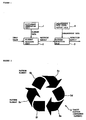
- Figure 1 a device for image recognition using pattern elements.
- the device of Figure 1 comprises a dictionary generating unit 1 which stores dictionary data concerning the target patterns to be detected. This dictionary data is obtained by dividing the target pattern (reference pattern) into a number of regions and storing each as a pattern element.
- the target pattern 5 shown in Figure 2 would be recorded in the dictionary generating unit 1 as a target pattern in its entirety.
- the target pattern is divided into a number of (here, six) regions, and dictionary data for each region is stored as pattern elements 5a through 5f.
- element matching unit 2 executes matching processing on the input image. It sends the results of the matching to the next stage, pattern detection unit 3.
- pattern detection unit 3 For the dictionary data associated with the target pattern in Figure 2, the six pattern elements 5a through 5f are read out (i.e., taken out of dictionary generating unit 1), and matching is executed with respect to each element. A determination is made as to whether the target pattern elements can be found in each input image. If they are found, the matching results are sent, together with their position data, to pattern detection unit 3. In this case the data consist of a set indicating which pattern element was found in which location.
- the location of the element consists of the coordinates of the center of the detected pattern element.
- element matching unit 2 also has the capacity to detect this center location. Since the processing by which the input image data is matched against the individual target pattern elements can be the same as that used in prior art devices, we will not provide a detailed explanation of it here.
- pattern detection unit 3 determines whether the pattern elements in the input image, which match all of the target pattern elements, are in the proper locations. If they are, it concludes that the input image data that was received contains the target pattern, and it outputs the result that the target pattern has been recognized.
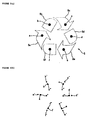
- the arrangement data stored in arrangement data generating unit 4 consists of the relative position coordinates which are defined by the center positions a through f of pattern elements 5a through 5f.
- the pattern shown in Figure 3 (a) is identical to pattern 5, which is to say that it represents the arrangement data for a magnification of 100%.
- the arrangement data in this embodiment is not limited to 100% only. Data for other magnifications are stored as well.
- arrangement data for a magnification of 115% consists of the relative position coordinates of center points a' through f'
- arrangement data for magnification of 95% consists of the relative position coordinates of center points a'' through f''.
- Arrangement data generating unit 4 outputs a magnification which was previously estimated or inferred from the input image data along with the arrangement data for those elements.
- the magnification is estimated from the magnification of the object to be recognized. In actuality, a number of magnifications are provided as output sequentially.
- the technique disclosed in Japanese Patent Publication 9-132763 may be applied, If an accurate magnification value can be obtained from the exterior, as in the case of a copier, arrangement data appropriate for the given magnification is provided as output.
- the entire target pattern 5 in Figure 2 will be used as a reference.
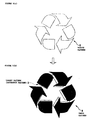
- the target pattern 5 shown by dotted lines in Figure 5 (a) is matched against the actual input pattern 6, the size difference will cause a significant discrepancy (see Figure 5 (b)), the probability of receiving a positive image recognition (the matching value) will be low, and target pattern 5 will not be recognized in the input pattern 6.
- each of the six target pattern elements 5a through 5f is compared to the corresponding input pattern element individually so that each is treated as a small independent region.
- the discrepancies caused by the magnification or reduction of the input image will for the most part be limited within a given input pattern element because the comparison is conducted in each region of the pattern elements. This regional comparison can result a sufficient accuracy in the matching process.
- element matching unit 2 will detect all of input pattern elements 6a through 6f and extract the center coordinates (indicated by white circles in the drawing) for each element. It will then transmit these coordinate values along with a descriptive notation (a number) for each element to pattern detection unit 3 as the result of the recognition routine.
- Pattern detection unit 3 compares the coordinate values sequentially with the plurality of reference arrangement data associated with each magnification which it receives from arrangement data generating unit 4. From this comparison, it determines whether the relative positional relationship of the input pattern elements that were detected matches the arrangement data for any of the magnifications, and so determines whether the input and target patterns match. In the example shown in Figure 6, the relationship matches the arrangement data for a magnification of 115%, so it is determined that the detected input pattern matches the target pattern. A result indicating this match is output from pattern detection unit 3.
- Resolution is one of the crucial elements in determining the presence of a pattern element. For example, when each comparison region is reduced for each input pattern element according to this embodiment, but elements 5a through 5f are changed to the higher resolution, then the detection can not be precisely carried out. This is because the total number of pixels in an image will increase or decrease according to the magnification ratio.
- the input pattern magnified to 115% When one region of the image in target pattern 5 contains a square with 100 pixels in it, the input pattern magnified to 115% will have 115 pixels. The magnified input pattern of 115% will increase by 15 pixels. When that same target pattern 5 is divided into ten equal segments, each segment will contain a square consisting of 10 pixels. So even though the entire input pattern has been magnified to 115% of its original size, each input pattern element will consist of only 11.5 pixels, an increase of only one to two pixels. The input pattern elements can thus be detected in the target pattern elements almost without any effect from the magnification, thus ensuring that both matching and detection can be accomplished with acceptable accuracy.
- each segment forming a pattern element will be a square containing 100 pixels. In this case, if the entire image is magnified to 115% of its original size, there will be fifteen extra pixels in each segment, and the accuracy of detection will suffer.
- magnification refers to a low magnification which an ordinary person cannot discriminate or recognize with his naked eye. Magnification ratios large enough to distinguish with the naked eye need not be addressed. If the dimensions of the copy are obviously different from those of the original, so that a counterfeit banknote can easily be distinguished at a glance, there is no need for countermeasures.
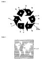
- Figure 7 shows another example of a pattern to be recognized.
- the pattern 5 shown in Figure 2 consisted of a number of shapes, so it could easily be divided into elements; however, the invention is not limited to this sort of pattern only, but is also applicable for patterns like that shown in Figure 7, which do not lend themselves easily to being divided.
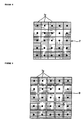
- the pattern shown in Figure 7 is continuous, so it would be difficult to divide it along the shapes in the pattern. It could, however, be divided using the mesh pattern in Figure 8 into twenty-five pattern elements 7a.
- the black circle in the center of each element 7a marks its center position. If, as is shown in Figure 9, this pattern is enlarged, pattern elements 7a can all be moved slightly away from each other. The corresponding portions of pattern 9 can then be matched against the pattern elements, and the pattern will be recognized despite the magnification.
- the image recognition device for this purpose would be configured as in Figure 1.
- the pattern may be divided into elements using schemes other than a mesh.
- the pattern elements could, for example, be circular, which would make the effect of a change in scale isotropic. However, if the pattern is divided into circular pattern elements which are not overlapped, there will be gaps between the circles. To eliminate these gaps, we can create more elements to overlap the circles and cover these gaps. When overlapping elements are used, the accuracy of matching elements may be affected; however, this is an effective way to deal with a magnified or reduced image, since the overall accuracy will be enhanced.
- Hexagonal elements which might be viewed as intermediate between round and square elements, could also be used to create a pattern like a honeycomb. In addition to those mentioned, any number of other shapes could also be used.
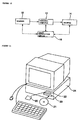
- Figure 10 illustrates a preferred embodiment of an image processing system comprising an image processing device in accordance with the present invention.
- the document is read by a scanner 10, the image input device, and the resulting image data is sent to personal computer 12, the image processing device.
- Personal computer 12 executes the prescribed processing on the input image data it receives and outputs the processed data to printer 14, the image generating device. Using the data it receives, printer 14 prints an image on the paper and outputs it.
- the processing executed by personal computer 12 might include changing the scale of the image, modifying it, correcting its color, or any of a variety of possible operations.
- the image could also be stored in any of a variety of recording media instead of being sent directly to printer 14.
- the processing to enlarge or reduce the image need not be limited to personal computer 12. It could also be executed when scanner 10 reads the image or just before printer 14 outputs it.
- the image input device need not be a scanner. It could also be a digital camera (either still or video) or any of a variety of devices.
- the scheme used to input the image need not be limited to the use of an image input device like scanner 10, as described above.
- a recording medium such as floppy disc or magnetic optical disc could also be used, or the image could be inputted electronically.
- image recognition device 16 is connected to personal computer 12.
- Image recognition device 16 has the configuration shown in Figure 1. It receives the input image data from personal computer 12 and executes the specified image recognition routine. If it determines that the image data it is processing contains the target image, it sends personal computer 12 a message indicating that result. When it receives such a message, personal computer 12 interrupts its normal image processing. It may simply stop processing the image, or it may reduce the resolution, cause the entire image to be a given color (for example, black), or superimpose a letter or mark on the image so that anyone can see at a glance that the bill or document is counterfeit or a copy.
- a given color for example, black
- the result of recognition may be output either to personal computer 12 or to printer 14.
- personal computer 12 is not the only possible source of the input image data.
- the input image data may also originate in scanner 10 or printer 14. In case the input image is received from scanner 10, the result of recognition may be sent directly to scanner 10.
- Image recognition device 16 may be a discrete device (including a board) which is attached to personal computer 12, or it may consist of application software installed in personal computer 12. In this case, image recognition device 16 would be built into the personal computer 12 shown in Figure 10. In an image processing system, image recognition device 16 could be installed in scanner 10 or printer 14 at the user's discretion.
- arrangement data needed to deal with changes in the scale of the image is stored ahead of time in arrangement data generating unit 4 of Figure 1.
- the invention is not limited to this scheme only.
- arrangement data for 100% of original size could be stored, and data for different magnifications could be generated by enlarging or reducing the image as needed for each image presented.
- the processing to accomplish this magnification or reduction could be also executed by pattern detection unit 3.
- the program system was stored ahead of time in the personal computer 12, which was treated as a single device.
- the invention is not limited to this case only. There could be an application program which caused the computer to execute all the processing routines, and this program could be stored in a given storage medium.
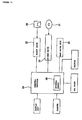
- floppy disk 20 or CD-ROM 21 could be used as the storage medium.
- the program stored on storage medium 20 or 21 would then be installed in hard drive unit 25, which is connected to (or installed in) personal computer 24 via floppy drive 22 or CD-ROM drive 23.
- personal computer 24 will acquire the configuration discussed in the above embodiment.
- the matching processing executed in element matching unit 2 and pattern detection unit 3 and the program which detects the center positions and determines the matching of the arrangement data could actually be installed in hard drive unit 25. Then when needed, this functionality could be transmitted from hard drive unit 25 to internal memory 26, where processing units 2 and 3 would be constructed. In this way all the processing could be executed at a high speed.
- the dictionary data in generating unit 1 and the arrangement data in generating unit 4 could also be realized in hard drive unit 25 or internal memory 26.
- this generating function may be performed by a program which is installed, like processing units 2 and 3 discussed above, in hard drive unit 25. When needed, this program would be transmitted from hard drive unit 25 to internal memory 26.
- the image recognition device, recording medium and image processing device can recognize an image which has been distorted so that its size and/or shape differ from the original image. This is performed by dividing the image into smaller elements and comparing each input image element with the corresponding element of a target pattern. This approach absorbs the differences in size and shape and thus allows the distorted image to be recognized.
- data concerning the relative arrangement of the elements is also considered in the final determination of whether the input image data contains the target image. This use of relative position data effectively minimizes any detrimental effect the scheme might have on recognition rate.
Landscapes
- Engineering & Computer Science (AREA)
- Computer Vision & Pattern Recognition (AREA)
- Physics & Mathematics (AREA)
- General Physics & Mathematics (AREA)
- Multimedia (AREA)
- Theoretical Computer Science (AREA)
- Image Analysis (AREA)
- Facsimile Image Signal Circuits (AREA)
- Inspection Of Paper Currency And Valuable Securities (AREA)
- Image Processing (AREA)
- Collating Specific Patterns (AREA)
Abstract
Description
Claims (19)
- An image recognition device, comprising:an element matching means to match a plurality of input pattern elements obtained by dividing an input image into a plurality of regions with the corresponding target pattern elements of a target pattern; anda pattern detection means to detect relative positions of said plurality of input pattern elements compared with reference arrangement data of said target pattern elements in order to recognize whether said input image includes said target pattern.
- An image recognition device, comprising:a dictionary generating unit which stores dictionary data for each pattern element in a target pattern;an element matching unit, which compares and matches input image pattern data which is provided as input against said dictionary data stored in said dictionary generating unit;an arrangement data generating unit which stores the position data representing the arrangement of the target pattern elements; anda pattern detection unit, which based on the output of said element matching unit and said position data from said arrangement data generating unit, determines whether said target pattern can be found in said input image pattern data.
- The image recognition device of claim 2, wherein said dictionary generating unit comprises a software routine.
- The image recognition device of claim 2, wherein said element matching unit comprises a software routine.
- The image recognition device of claim 2, wherein said arrangement data generating unit comprises a software routine.
- The image recognition device of claim 2, wherein said pattern detection unit comprises a software routine.
- An image processing device, comprising:an element matching means to match a plurality of input pattern elements obtained by dividing an input image into a plurality of regions with the corresponding target pattern elements of a target pattern;a pattern detection means to detect relative positions of said plurality of input pattern elements compared with a reference arrangement data of said target pattern elements in order to recognize whether said input image includes said target pattern; anda control means to control output of said input image to an output device when said pattern detection means recognizes said input image includes said target pattern.
- The image processing device of claim 7, wherein said output device comprises a printer.
- The image processing device of claim 7 further comprising a scanner to input said input image into said image processing device.
- The image processing device of claim 7 further comprising a digital camera to input said input image into said image processing device.
- The image processing device of claim 7 further comprising a floppy disc to input said input image into said image processing device.
- The image processing device of claim 7 further comprises a personal computer to facilitate copying of said input image.
- A recording medium for an image recognition method, comprising:an element matching means to match a plurality of input pattern elements obtained by dividing an input image into a plurality of regions with corresponding target pattern elements of a target pattern; anda pattern detection means to detect relative positions of said plurality of input pattern elements compared with a reference arrangement data of said target pattern elements in order to recognize whether said input image includes said target pattern.
- A method of processing an image, said method comprising:inputting a reference image;determining target pattern elements for said reference image by dividing said reference image into a plurality of regions;determining arrangement data for said target pattern elements;inputting data for an input image;determining input elements for said input image by dividing said input image into said plurality of regions corresponding to said reference image; andcomparing said target pattern elements and said input elements.
- The method of claim 14, wherein said comparing comprises comparing said target pattern elements and said input elements relative position to each other using said arrangement data.
- The method of claim 14 further comprising halting the process if said target pattern elements include said input elements based on said comparing.
- The method of claim 14 further comprising changing the color of a reproduction of said input image if said target pattern elements include said input elements based on said comparing.
- The method of claim 14 further comprising reducing the resolution of a reproduction of said input image if said target pattern elements include said input elements based on said comparing.
- The method of claim 14 further comprising superimposing a character on top of a reproduction of said input image if said target pattern elements include said input elements based on said comparing.
Applications Claiming Priority (2)
| Application Number | Priority Date | Filing Date | Title |
|---|---|---|---|
| JP00243799A JP3963053B2 (en) | 1999-01-08 | 1999-01-08 | Image recognition apparatus, recording medium, and image processing apparatus |
| JP243799 | 1999-01-08 |
Publications (3)
| Publication Number | Publication Date |
|---|---|
| EP1018700A2 true EP1018700A2 (en) | 2000-07-12 |
| EP1018700A3 EP1018700A3 (en) | 2003-10-29 |
| EP1018700B1 EP1018700B1 (en) | 2006-09-13 |
Family
ID=11529257
Family Applications (1)
| Application Number | Title | Priority Date | Filing Date |
|---|---|---|---|
| EP00100150A Expired - Lifetime EP1018700B1 (en) | 1999-01-08 | 2000-01-10 | An image recognition device using pattern elements |
Country Status (4)
| Country | Link |
|---|---|
| US (1) | US7272260B1 (en) |
| EP (1) | EP1018700B1 (en) |
| JP (1) | JP3963053B2 (en) |
| DE (1) | DE60030603T2 (en) |
Cited By (4)
| Publication number | Priority date | Publication date | Assignee | Title |
|---|---|---|---|---|
| AT412593B (en) * | 2003-03-31 | 2005-04-25 | Oebs Gmbh | PROCESS FOR CALIBRATION |
| EP1229487A3 (en) * | 2001-01-25 | 2006-05-03 | Ricoh Company, Ltd. | Image recognition scheme |
| WO2007004868A1 (en) * | 2005-07-06 | 2007-01-11 | Universiteit Van Amsterdam | Method and apparatus for image characterization |
| RU2507538C2 (en) * | 2009-10-19 | 2014-02-20 | Алексей Александрович Галицын | Method for group identification of objects ("friendly-foreign") and target designation based on real-time wireless positioning and intelligent radar |
Families Citing this family (5)
| Publication number | Priority date | Publication date | Assignee | Title |
|---|---|---|---|---|
| US7792611B2 (en) * | 2004-10-01 | 2010-09-07 | Ingo Werner Scheer | Spray pattern characterization and monitoring method and system |
| US8798313B2 (en) * | 2009-07-09 | 2014-08-05 | Hewlett-Packard Development Company, L.P. | Counterfeit detection system |
| CN103959309B (en) | 2011-10-03 | 2017-09-12 | 惠普发展公司,有限责任合伙企业 | The regional choice determined for counterfeit |
| JP6282040B2 (en) * | 2013-03-25 | 2018-02-21 | 株式会社高見沢サイバネティックス | Paper sheet discrimination device and paper sheet discrimination method |
| JP2014215877A (en) * | 2013-04-26 | 2014-11-17 | 株式会社デンソー | Object detection device |
Family Cites Families (20)
| Publication number | Priority date | Publication date | Assignee | Title |
|---|---|---|---|---|
| DE1774314B1 (en) * | 1968-05-22 | 1972-03-23 | Standard Elek K Lorenz Ag | DEVICE FOR MACHINE CHARACTER RECOGNITION |
| CH609795A5 (en) * | 1976-04-30 | 1979-03-15 | Gretag Ag | |
| US4955062A (en) * | 1986-12-10 | 1990-09-04 | Canon Kabushiki Kaisha | Pattern detecting method and apparatus |
| US5321470A (en) * | 1988-05-13 | 1994-06-14 | Canon Kabushiki Kaisha | Apparatus with anti-forgery provision |
| SG102585A1 (en) * | 1989-02-10 | 2004-03-26 | Canon Kk | Apparatus for image reading or processing |
| US5271068A (en) * | 1990-03-15 | 1993-12-14 | Sharp Kabushiki Kaisha | Character recognition device which divides a single character region into subregions to obtain a character code |
| CA2063785C (en) * | 1991-03-25 | 1998-09-29 | Masahiro Funada | Image processing apparatus |
| JP3501470B2 (en) * | 1992-05-08 | 2004-03-02 | キヤノン株式会社 | Image processing apparatus and method |
| JP3115736B2 (en) * | 1993-01-18 | 2000-12-11 | シャープ株式会社 | Image processing device |
| JP3397843B2 (en) | 1993-07-23 | 2003-04-21 | 株式会社リコー | Copier |
| US6463176B1 (en) * | 1994-02-02 | 2002-10-08 | Canon Kabushiki Kaisha | Image recognition/reproduction method and apparatus |
| US5987173A (en) * | 1995-03-27 | 1999-11-16 | Nippon Steel Corporation | Interactive drawing recognition processing method and apparatus thereof |
| AUPN310095A0 (en) * | 1995-05-22 | 1995-06-15 | Canon Kabushiki Kaisha | Image detection system |
| JP3679495B2 (en) | 1996-03-22 | 2005-08-03 | キヤノン株式会社 | Image processing apparatus and method |
| JP3787922B2 (en) | 1996-10-11 | 2006-06-21 | オムロン株式会社 | Image processing method and apparatus, and printer using the same |
| JPH10150542A (en) | 1996-11-15 | 1998-06-02 | Omron Corp | Image processing method and image processing system |
| JPH10162101A (en) * | 1996-11-28 | 1998-06-19 | Hitachi Ltd | Handwritten character recognition device and handwritten character recognition method |
| JP3781850B2 (en) * | 1997-01-21 | 2006-05-31 | シャープ株式会社 | Image forming system |
| US6272245B1 (en) * | 1998-01-23 | 2001-08-07 | Seiko Epson Corporation | Apparatus and method for pattern recognition |
| US6370271B2 (en) * | 1999-04-30 | 2002-04-09 | Seiko Epson Corporation | Image processing apparatus and methods for pattern recognition |
-
1999
- 1999-01-08 JP JP00243799A patent/JP3963053B2/en not_active Expired - Fee Related
-
2000
- 2000-01-10 US US09/479,886 patent/US7272260B1/en not_active Expired - Fee Related
- 2000-01-10 EP EP00100150A patent/EP1018700B1/en not_active Expired - Lifetime
- 2000-01-10 DE DE60030603T patent/DE60030603T2/en not_active Expired - Lifetime
Cited By (6)
| Publication number | Priority date | Publication date | Assignee | Title |
|---|---|---|---|---|
| EP1229487A3 (en) * | 2001-01-25 | 2006-05-03 | Ricoh Company, Ltd. | Image recognition scheme |
| US7139429B2 (en) | 2001-01-25 | 2006-11-21 | Ricoh Company, Ltd. | Image recognition scheme |
| AT412593B (en) * | 2003-03-31 | 2005-04-25 | Oebs Gmbh | PROCESS FOR CALIBRATION |
| WO2007004868A1 (en) * | 2005-07-06 | 2007-01-11 | Universiteit Van Amsterdam | Method and apparatus for image characterization |
| WO2007004864A1 (en) * | 2005-07-06 | 2007-01-11 | Universiteit Vam Amsterdam | Method and apparatus for visual object recognition |
| RU2507538C2 (en) * | 2009-10-19 | 2014-02-20 | Алексей Александрович Галицын | Method for group identification of objects ("friendly-foreign") and target designation based on real-time wireless positioning and intelligent radar |
Also Published As
| Publication number | Publication date |
|---|---|
| US7272260B1 (en) | 2007-09-18 |
| EP1018700B1 (en) | 2006-09-13 |
| JP3963053B2 (en) | 2007-08-22 |
| DE60030603T2 (en) | 2007-09-13 |
| EP1018700A3 (en) | 2003-10-29 |
| JP2000200352A (en) | 2000-07-18 |
| DE60030603D1 (en) | 2006-10-26 |
Similar Documents
| Publication | Publication Date | Title |
|---|---|---|
| US5629990A (en) | Image processing system | |
| US6272245B1 (en) | Apparatus and method for pattern recognition | |
| EP0940780B1 (en) | Image processing device and method for detecting a reference pattern | |
| EP1048987B1 (en) | Image processing device and image input device equipped with a data synthesizing unit | |
| KR19990006591A (en) | Image detection method, image detection device, image processing method, image processing device and medium | |
| JP2000333005A (en) | Pattern detection method, apparatus and recording medium | |
| JPH08340443A (en) | Method and apparatus for generating forgery possibility information, and equipment using them | |
| JPH06318282A (en) | Inspection method and device for printed picture such as document | |
| EP1755327B1 (en) | Detection of document security marks using run profiles | |
| US7272260B1 (en) | Image recognition-processing device and method using pattern elements | |
| JP4219547B2 (en) | Counterfeit detection method | |
| JPH10150548A (en) | Image input device and image processing system | |
| US6928190B2 (en) | Image discrimination apparatus, copier and image discrimination method | |
| KR100874752B1 (en) | Banknote Recognition Device and Recognition Method | |
| KR101287811B1 (en) | Hierarchical miniature security marks | |
| JP3787922B2 (en) | Image processing method and apparatus, and printer using the same | |
| JP4014070B2 (en) | Pattern detection method and image processing control method | |
| JP3253363B2 (en) | Copier with special document identification function | |
| JPH07143335A (en) | Apparatus and method for preventing copy prohibition copy in color copying machine | |
| JPH10150542A (en) | Image processing method and image processing system | |
| JPH06251128A (en) | Image processor and copying machine using its processor | |
| JP2006039732A (en) | Image discrimination method and medium processor using the same | |
| JP3202806B2 (en) | Copier with special document identification function | |
| JPH07123254A (en) | Image forming device | |
| JPH0670158A (en) | Image processor |
Legal Events
| Date | Code | Title | Description |
|---|---|---|---|
| PUAI | Public reference made under article 153(3) epc to a published international application that has entered the european phase |
Free format text: ORIGINAL CODE: 0009012 |
|
| AK | Designated contracting states |
Kind code of ref document: A2 Designated state(s): AT BE CH DE DK ES FI FR GB GR IE IT LI LU MC NL PT SE |
|
| AX | Request for extension of the european patent |
Free format text: AL;LT;LV;MK;RO;SI |
|
| 17P | Request for examination filed |
Effective date: 20000821 |
|
| PUAL | Search report despatched |
Free format text: ORIGINAL CODE: 0009013 |
|
| AK | Designated contracting states |
Kind code of ref document: A3 Designated state(s): AT BE CH DE DK ES FI FR GB GR IE IT LI LU MC NL PT SE |
|
| AX | Request for extension of the european patent |
Extension state: AL LT LV MK RO SI |
|
| RIC1 | Information provided on ipc code assigned before grant |
Ipc: 7G 06K 9/46 A Ipc: 7G 07D 7/20 B |
|
| 17Q | First examination report despatched |
Effective date: 20040420 |
|
| AKX | Designation fees paid |
Designated state(s): DE FR GB |
|
| GRAP | Despatch of communication of intention to grant a patent |
Free format text: ORIGINAL CODE: EPIDOSNIGR1 |
|
| GRAS | Grant fee paid |
Free format text: ORIGINAL CODE: EPIDOSNIGR3 |
|
| GRAA | (expected) grant |
Free format text: ORIGINAL CODE: 0009210 |
|
| AK | Designated contracting states |
Kind code of ref document: B1 Designated state(s): DE FR GB |
|
| REG | Reference to a national code |
Ref country code: GB Ref legal event code: FG4D |
|
| REF | Corresponds to: |
Ref document number: 60030603 Country of ref document: DE Date of ref document: 20061026 Kind code of ref document: P |
|
| ET | Fr: translation filed | ||
| PLBE | No opposition filed within time limit |
Free format text: ORIGINAL CODE: 0009261 |
|
| STAA | Information on the status of an ep patent application or granted ep patent |
Free format text: STATUS: NO OPPOSITION FILED WITHIN TIME LIMIT |
|
| 26N | No opposition filed |
Effective date: 20070614 |
|
| PGFP | Annual fee paid to national office [announced via postgrant information from national office to epo] |
Ref country code: DE Payment date: 20140108 Year of fee payment: 15 |
|
| PGFP | Annual fee paid to national office [announced via postgrant information from national office to epo] |
Ref country code: FR Payment date: 20140108 Year of fee payment: 15 |
|
| PGFP | Annual fee paid to national office [announced via postgrant information from national office to epo] |
Ref country code: GB Payment date: 20140108 Year of fee payment: 15 |
|
| REG | Reference to a national code |
Ref country code: DE Ref legal event code: R119 Ref document number: 60030603 Country of ref document: DE |
|
| GBPC | Gb: european patent ceased through non-payment of renewal fee |
Effective date: 20150110 |
|
| PG25 | Lapsed in a contracting state [announced via postgrant information from national office to epo] |
Ref country code: GB Free format text: LAPSE BECAUSE OF NON-PAYMENT OF DUE FEES Effective date: 20150110 Ref country code: DE Free format text: LAPSE BECAUSE OF NON-PAYMENT OF DUE FEES Effective date: 20150801 |
|
| REG | Reference to a national code |
Ref country code: FR Ref legal event code: ST Effective date: 20150930 |
|
| PG25 | Lapsed in a contracting state [announced via postgrant information from national office to epo] |
Ref country code: FR Free format text: LAPSE BECAUSE OF NON-PAYMENT OF DUE FEES Effective date: 20150202 |