EP1018582B1 - Element for finishing a narrow wall part when realizing plaster work and method for manufacturing such element - Google Patents
Element for finishing a narrow wall part when realizing plaster work and method for manufacturing such element Download PDFInfo
- Publication number
- EP1018582B1 EP1018582B1 EP00200025A EP00200025A EP1018582B1 EP 1018582 B1 EP1018582 B1 EP 1018582B1 EP 00200025 A EP00200025 A EP 00200025A EP 00200025 A EP00200025 A EP 00200025A EP 1018582 B1 EP1018582 B1 EP 1018582B1
- Authority
- EP
- European Patent Office
- Prior art keywords
- plate
- corner
- element according
- aforementioned
- wall part
- Prior art date
- Legal status (The legal status is an assumption and is not a legal conclusion. Google has not performed a legal analysis and makes no representation as to the accuracy of the status listed.)
- Expired - Lifetime
Links
- 239000011505 plaster Substances 0.000 title claims abstract description 33
- 238000000034 method Methods 0.000 title claims description 13
- 238000004519 manufacturing process Methods 0.000 title claims description 7
- 229910052602 gypsum Inorganic materials 0.000 claims description 12
- 239000010440 gypsum Substances 0.000 claims description 12
- 239000011507 gypsum plaster Substances 0.000 claims description 12
- 239000003795 chemical substances by application Substances 0.000 claims description 7
- 239000000126 substance Substances 0.000 claims description 7
- 239000000945 filler Substances 0.000 claims description 6
- 239000003292 glue Substances 0.000 claims description 3
- 239000002184 metal Substances 0.000 claims description 2
- 238000003825 pressing Methods 0.000 claims description 2
- 239000000463 material Substances 0.000 description 6
- 238000010276 construction Methods 0.000 description 3
- 238000009499 grossing Methods 0.000 description 3
- 230000002787 reinforcement Effects 0.000 description 3
- 238000005034 decoration Methods 0.000 description 2
- 239000011888 foil Substances 0.000 description 2
- 238000009413 insulation Methods 0.000 description 2
- 238000003801 milling Methods 0.000 description 2
- 239000002985 plastic film Substances 0.000 description 2
- 229920006255 plastic film Polymers 0.000 description 2
- 230000001681 protective effect Effects 0.000 description 2
- 239000007787 solid Substances 0.000 description 2
- 229910001335 Galvanized steel Inorganic materials 0.000 description 1
- 238000005452 bending Methods 0.000 description 1
- 238000001035 drying Methods 0.000 description 1
- 239000008397 galvanized steel Substances 0.000 description 1
- 238000002513 implantation Methods 0.000 description 1
- 238000010422 painting Methods 0.000 description 1
- 230000001012 protector Effects 0.000 description 1
- 239000010935 stainless steel Substances 0.000 description 1
- 229910001220 stainless steel Inorganic materials 0.000 description 1
- 229920002994 synthetic fiber Polymers 0.000 description 1
Images



Classifications
-
- E—FIXED CONSTRUCTIONS
- E06—DOORS, WINDOWS, SHUTTERS, OR ROLLER BLINDS IN GENERAL; LADDERS
- E06B—FIXED OR MOVABLE CLOSURES FOR OPENINGS IN BUILDINGS, VEHICLES, FENCES OR LIKE ENCLOSURES IN GENERAL, e.g. DOORS, WINDOWS, BLINDS, GATES
- E06B1/00—Border constructions of openings in walls, floors, or ceilings; Frames to be rigidly mounted in such openings
- E06B1/04—Frames for doors, windows, or the like to be fixed in openings
- E06B1/34—Coverings, e.g. protecting against weather, for decorative purposes
- E06B1/342—Reveal covering members disposed alongside of a window frame
-
- E—FIXED CONSTRUCTIONS
- E04—BUILDING
- E04F—FINISHING WORK ON BUILDINGS, e.g. STAIRS, FLOORS
- E04F13/00—Coverings or linings, e.g. for walls or ceilings
- E04F13/02—Coverings or linings, e.g. for walls or ceilings of plastic materials hardening after applying, e.g. plaster
- E04F13/04—Bases for plaster
- E04F13/06—Edge-protecting borders
-
- E—FIXED CONSTRUCTIONS
- E04—BUILDING
- E04F—FINISHING WORK ON BUILDINGS, e.g. STAIRS, FLOORS
- E04F13/00—Coverings or linings, e.g. for walls or ceilings
- E04F13/02—Coverings or linings, e.g. for walls or ceilings of plastic materials hardening after applying, e.g. plaster
- E04F13/04—Bases for plaster
- E04F13/06—Edge-protecting borders
- E04F2013/063—Edge-protecting borders for corners
Definitions
- This invention relates to an element for finishing a narrow wall part when realizing plaster work, as well as to a method for manufacturing such element.
- a reveal when providing plaster work, is finished by providing a corner profile by means of a quantity of gypsum plaster or such on the rough masoned corner, formed by the side of the reveal and the interior wall. Subsequently, this profile is used by the stuccoer as a guide for smoothing the plaster on the side of the reveal, between this profile and the frame of the door or the window.
- Another disadvantage consists in that it is rather difficult to realize the plaster work over the entire depth of the reveal in a straight manner, as there is only one guide profile, namely the aforementioned corner profile. Finishing in the traditional manner therefore requires a high precision and handiness of the stuccoer.
- the present invention aims at an element which allows an easy finishing of a narrow wall part, such as a reveal or a column side, when carrying out plaster work, whereby in the case of finishing a reveal, it is no longer strictly required to cover the window or such, it is easier to provide for a straight line at the location of the frame, and finishing requires less time.
- the invention relates to an element for finishing a narrow wall part, such as a reveal or a column side, when realizing plaster work, with as a characteristic that this element at least consists of a strip-shaped plate for covering the wall part to be finished, whereby this plate, at least at one longitudinal edge, is provided with an auxiliary part for realizing a corner, to which part then, on one hand, the plate and, on the other hand, plaster work is adjoined.
- the aforementioned strip-shaped plate thus can be fixed against the side of the reveal by means of several props of wet gypsum, with the aforementioned auxiliary part at the location of the corner, between reveal and wall. Since a plate is applied, no plaster has to be smoothed alongside the window, as a result of which the covering with a tape or the like is no longer strictly required. Due to the plate, automatically a flat covering of the reveal and therefore also a straight line along the window is obtained.
- the auxiliary part allows to subsequently realize plaster work against the wall in which the window or the like is situated, which plaster work perfectly adjoins up to the realized reveal. Moreover, this auxiliary part forms a reinforcement against bending of the plate during its placement against the side of the reveal.
- DE-A-32.18.533 discloses an element consisting of a plate provided with a binding strip and a protective profile with a least one rectangular corner and more than two legs may be fixed on the plate or on an insulation plate with a damp shield to cover plaster work, and said profile and/or binding strip may extents over a corner whereby said binding strip is provided with a sharp sloping border in order that no marginal line would be visible through the wallpaper.
- This invention is used in the field of wall insulation, an essential disadvantage is that said application can only handle with smooth surfaces, thus the plaster work should already be present on the wall, and, that the head side protector is profiled rectangularly.
- DE-U-88.10.264 discloses clamping and protective profiles with a least one rectangular corner and more than two legs to be fixed on the head sides of a plate and which are different in shape depending on the fact if the element must extend over the corner or not.
- This invention is used in the field of wall decoration too but the easiness of attaching is completely annulled by a main disadvantage, namely after placing a plate on the reveal side of the wall a second plate, to cover the other side of the corner, should be cut and profiled in order to join with the shape of said element.
- Another disadvantage is that after placing, an empty stroke, between two of said elements, appears equal to the thickness of the material of said element, which still had to be filled up with plaster.
- an economic disadvantage of the said element is that for each thickness of plate another element is needed, and, that said element can not be applied on very rough surface, even not with the configuration presented in fig. 7. As can be seen in fig. 6 the said element should lean closely against the wall, otherwise the resulting construction will deform and will be not stable with the consequence that the join in the corner will break open.
- This invention has a main inconvenience in decoration, caused by the consequence of using two different materials appearing at the visible site of the plaster work. Different drying and thermal dilatation and shrinking of the plaster work, filling up the said empty stroke, compared to the material of the said element, will cause this join to rupture.
- the auxiliary part preferably consists of a corner profile extending in longitudinal direction of which one leg forms a flange connected to the plate, whereas the other leg forms a flange allowing an adherence in the plaster work to be realized subsequently.
- the auxiliary part and more particularly the aforementioned profile, preferably also has a portion defining a corner edge, in such a manner that it can be applied as a guide when realizing the plastering of the wall and it moreover offers a reinforcement extending up to the corner, as a result of which the corner is impact-resistant.
- the strip-shaped plate substantially consists of gypsum plaster, and even better of cardboard-covered gypsum plaster board.
- the element can easily be fixed against the wall part to be finished by means of several props of wet gypsum.
- the gypsum plate or the cardboard-covered gypsum plaster board indeed is particularly suitable for being adhered by means of wet gypsum.
- the aforementioned element preferably is manufactured as a prefabricated element, whereby the auxiliary part, more particularly the corner profile, is fixed at the plate during manufacturing.
- the invention also relates to a method for manufacturing such element, with as a characteristic that it consists in forming a strip-shaped plate of cardboard-covered gypsum plaster board; providing a groove in at least one longitudinal narrow side of the plate; and providing and attaching a corner profile with one leg in this groove.
- the invention also relates to a method for finishing a reveal, whereby use is made of an element as described above, with as a characteristic that this method consists in bringing the element to the required length and width; providing a quantity of adherence substance, more particularly gypsum, on the unfinished reveal; pressing and positioning the aforementioned element against this adherence substance; and, after the aforementioned adherence substance has sufficiently hardened, plastering the wall part adjoining perpendicular to the reveal, whereby the aforementioned element, more particularly the pertaining auxiliary part, is used as a guide for plastering.
- a reveal 1 in other words, the lateral face of a wall 2 around a window 3 or such, is finished in a traditional manner by first, as represented in figures 1 and 2, fixing a corner profile 4 by means of a quantity of gypsum plaster 5, or in any other manner, and covering the window 3 by means of a film 6 or such, as a protection against spoiling, and subsequently, after the corner profile 4 is fixed sufficiently by the hardening of the gypsum plaster 5, plastering the reveal 1 as well as the wall side 7 in a classical manner.
- the corner profile 4 is used as a guide for smoothing the gypsum plaster 8. It is obvious that at the location of the reveal 1, there is only one guide and that this traditional technique consequently has the disadvantage that it is rather difficult to realize a straight line 9 at the window 3.
- Another disadvantage consists in that the window 3 has to be protected by means of a film 6, or at least a tape, which, as already mentioned in the introduction, is time-consuming, in respect to application as well as removal.
- the present invention aims at an element with which a narrow wall part, such as the aforementioned reveal 1, can easily be finished during the realization of plaster works.
- This element 10 consists of a strip-shaped plate 11 for covering the wall part to be finished, whereby this plate 11, in this case at one longitudinal edge 12, is provided with an auxiliary part for realizing a corner, which auxiliary part in this case is formed by a corner profile 13 extending in the longitudinal direction of the plate 11.
- the plate 11 preferably consists of a cardboard-covered gypsum plaster board, in other words, a plate with a core 14 of gypsum or similar and two top layers 15-16 of cardboard.
- the corner profile 13 preferably consists of metal, more particularly stainless and/or galvanized steel. According to the invention, it is, however, not excluded to realize it in other materials, such as, for example, synthetic material.
- the corner profile 13 may be fixed at the plate 11 with one leg 17 in the plate 11 itself.
- the second leg 18 forms a fixation- and/or adherence flange which extends at an angle in respect to the plate 11 and which can cooperate with plaster work.
- the legs 17 and 18, as represented, preferably extend at an angle which is smaller than 90°, such as this is also usual for standard corner profiles for realizing a corner with traditional plaster work.
- the corner profile 13 shows a portion 19 defining a corner edge, more particularly a portion 19 adjoining against the prolongation of the surface 20 of the plate 11.
- the portion 19 preferably is realized bead-shaped, such that thereby a small rounding at the location of the corner to be realized is obtained.
- the corner profile 13 preferably is fixed at the plate 11 in the manner as represented in figures 7 to 9.
- a groove 21 is realized in the longitudinal edge 12 of the plate 11, preferably by means of a milling process.
- the corner profile 13 is accurately positioned in the groove 21 and fixed therein by means of an adherence agent 22.
- this adherence agent 22 can first be applied in the groove 21, after which the corner profile 13, before the adherence agent 22 has hardened, is pressed on therein.
- the adherence agent 22 preferably consists of glue, but it is not excluded to apply other materials to this aim, such as any other hardening filling matter.
- the legs 17 and 18 of the corner profile 13 preferably are provided with means offering a better adherence, on one hand, in the adherence agent 22 and, on the other hand, in the plaster work to be realized subsequently, which means in the example consist of openings 23 as well as profiled edges 24.
- the groove 21 in the aforementioned first step is realized preferably such that, when the corner profile 13 is pressed with the round portion 19 against the longitudinal edge 12 and also is pressed on in such a manner that, as represented in figure 8, at the locations A and B a contact with the opposed sides of the groove 21 is made, this corner profile 13 is situated in correct position, in other words, the portion 19 is brought precisely to equal height with the surface 20.
- the small open joint between the portion 19 and the longitudinal edge 12 of the plate 11 can eventually be filled with a filling agent 25, as represented in figure 9.
- a flexible joint filler will be used.
- the element 10 preferably is realized as a prefabricated element, more particularly an element which is composed before being placed, as described hereafter, against the wall part to be finished.
- the prefabricated element 10 preferably shall be realized factory-built.
- Figures 10 and 11 represent how a reveal 1 is realized by means of an element 10 according to the invention.
- the plate 11 is sawn or cut to size. It is noted that the elements 10 can be fabricated and commercialized with different standard widths, such that, by choosing the just width, the element 10 only has to be sawn or cut to the right length.
- the element 10 brought to size is fixed against the rough surface 26 of the reveal by means of a quantity of wet gypsum 27 or any other adherence substance, such as represented in figure 10. It is obvious that the window profiles or the window panes of the window 3 hereby not necessarily will have to be covered by tape or similar, as by the, so to speak, "dry" finishing of the reveals 1, the risk of spoiling is practically nonexistent.
- finishing of reveals 1 in this manner is considerably easier than in the case of traditional plaster work.
- the finishing of the reveals 1 then does not necessarily have to be performed by skilled stuccoers but can also be easily realized by, for example, the persons applying the window 3, or by less skilled do-it-yourselfers.
- the element 10 can be realized in different variants while still remaining within the scope of the invention. So, for example, does the aforementioned auxiliary part for realizing the corner not necessarily have to consist of a corner profile 13.
- This auxiliary part for example, may also be formed of a profile or another element which exclusively offers an edge reinforcement at the longitudinal edge 12 of the plate 11, without the presence of the aforementioned leg 18.
- a fixation or adherence flange in the form of a leg 18 of a corner profile 13
- use can also be made of other adherence means, or such adherence means even may be omitted.
- Another form of possible adherence means is a net or a fleece which is fixed at the plate 11 and which is folded around the corner when finishing the reveal 1 and is plastered into the plaster work 28.
- the auxiliary part preferably extends continuously over the longitudinal edge 12.
- a corner profile 13 might be used, the legs 17-18 of which, with well-defined interstices, for example, every centimeter, are cut in transverse direction up to the portion 19 forming the actual corner, in such a manner that, when the cardboard of the cardboard-covered gypsum plaster board is cut exactly at the height of such a cut, the element 10, by folding the plate 11, can simply be broken in two. Hereby, the portion 19 at this height will break. Eventually, it is also possible to simply cut this portion 19 previously by means of nipper pliers.
- the plate 11 may consist of pure gypsum or be covered by cardboard on only one side.
- the plate 1 can be provided at its rear side with ribs or similar, as a result of which the plate 1 is reinforced and a better adherence in the gypsum 27 or in another adherence agent is obtained during application.
- the plate 11 possibly can also be provided at both longitudinal edges 12 and 29 with an auxiliary part, more particularly a corner profile 13, as a result of which elements 30 are obtained with which, as represented in figure 12, a covering around a column 31 or similar can be realized.
- element 30 is provided at two sides of the column 31, after which the other sides can be finished by means of classical plaster work 32.
Landscapes
- Engineering & Computer Science (AREA)
- Civil Engineering (AREA)
- Structural Engineering (AREA)
- Architecture (AREA)
- Finishing Walls (AREA)
- Electrical Discharge Machining, Electrochemical Machining, And Combined Machining (AREA)
- Building Environments (AREA)
- Polishing Bodies And Polishing Tools (AREA)
Abstract
Description
- This invention relates to an element for finishing a narrow wall part when realizing plaster work, as well as to a method for manufacturing such element.
- More particularly, it aims at an element for finishing a reveal or a column side.
- Traditionally, a reveal, when providing plaster work, is finished by providing a corner profile by means of a quantity of gypsum plaster or such on the rough masoned corner, formed by the side of the reveal and the interior wall. Subsequently, this profile is used by the stuccoer as a guide for smoothing the plaster on the side of the reveal, between this profile and the frame of the door or the window.
- This traditional manner of working has various disadvantages. The frame of the door or the window indeed has to be covered with tape and/or plastic film in order to avoid being spoiled. Also, window panes which eventually have been already provided, would have to be covered with tape. After plastering, the tape and/or plastic film has to be removed. It is obvious that this is time-consuming and expensive.
- Another disadvantage consists in that it is rather difficult to realize the plaster work over the entire depth of the reveal in a straight manner, as there is only one guide profile, namely the aforementioned corner profile. Finishing in the traditional manner therefore requires a high precision and handiness of the stuccoer.
- The present invention aims at an element which allows an easy finishing of a narrow wall part, such as a reveal or a column side, when carrying out plaster work, whereby in the case of finishing a reveal, it is no longer strictly required to cover the window or such, it is easier to provide for a straight line at the location of the frame, and finishing requires less time.
- To this aim, the invention relates to an element for finishing a narrow wall part, such as a reveal or a column side, when realizing plaster work, with as a characteristic that this element at least consists of a strip-shaped plate for covering the wall part to be finished, whereby this plate, at least at one longitudinal edge, is provided with an auxiliary part for realizing a corner, to which part then, on one hand, the plate and, on the other hand, plaster work is adjoined.
- In the case of finishing a reveal, the aforementioned strip-shaped plate thus can be fixed against the side of the reveal by means of several props of wet gypsum, with the aforementioned auxiliary part at the location of the corner, between reveal and wall. Since a plate is applied, no plaster has to be smoothed alongside the window, as a result of which the covering with a tape or the like is no longer strictly required. Due to the plate, automatically a flat covering of the reveal and therefore also a straight line along the window is obtained. The auxiliary part allows to subsequently realize plaster work against the wall in which the window or the like is situated, which plaster work perfectly adjoins up to the realized reveal. Moreover, this auxiliary part forms a reinforcement against bending of the plate during its placement against the side of the reveal.
- DE-A-32.18.533 discloses an element consisting of a plate provided with a binding strip and a protective profile with a least one rectangular corner and more than two legs may be fixed on the plate or on an insulation plate with a damp shield to cover plaster work, and said profile and/or binding strip may extents over a corner whereby said binding strip is provided with a sharp sloping border in order that no marginal line would be visible through the wallpaper.
- This invention is used in the field of wall insulation, an essential disadvantage is that said application can only handle with smooth surfaces, thus the plaster work should already be present on the wall, and, that the head side protector is profiled rectangularly.
- An additional inconvenience is that said application is intended to be covered by wallpaper as the construction foil, will stay visible after painting, even when this construction foil is provided with a sharp sloping border.
- DE-U-88.10.264 discloses clamping and protective profiles with a least one rectangular corner and more than two legs to be fixed on the head sides of a plate and which are different in shape depending on the fact if the element must extend over the corner or not.
- This invention is used in the field of wall decoration too but the easiness of attaching is completely annulled by a main disadvantage, namely after placing a plate on the reveal side of the wall a second plate, to cover the other side of the corner, should be cut and profiled in order to join with the shape of said element.
- Another disadvantage is that after placing, an empty stroke, between two of said elements, appears equal to the thickness of the material of said element, which still had to be filled up with plaster.
- Moreover, an economic disadvantage of the said element is that for each thickness of plate another element is needed, and, that said element can not be applied on very rough surface, even not with the configuration presented in fig. 7. As can be seen in fig. 6 the said element should lean closely against the wall, otherwise the resulting construction will deform and will be not stable with the consequence that the join in the corner will break open.
- This invention has a main inconvenience in decoration, caused by the consequence of using two different materials appearing at the visible site of the plaster work. Different drying and thermal dilatation and shrinking of the plaster work, filling up the said empty stroke, compared to the material of the said element, will cause this join to rupture.
- The above disadvantages are overcome by the element according to claim 1.
- The auxiliary part preferably consists of a corner profile extending in longitudinal direction of which one leg forms a flange connected to the plate, whereas the other leg forms a flange allowing an adherence in the plaster work to be realized subsequently.
- The auxiliary part, and more particularly the aforementioned profile, preferably also has a portion defining a corner edge, in such a manner that it can be applied as a guide when realizing the plastering of the wall and it moreover offers a reinforcement extending up to the corner, as a result of which the corner is impact-resistant.
- Preferably, the strip-shaped plate substantially consists of gypsum plaster, and even better of cardboard-covered gypsum plaster board. As a result of this, the element can easily be fixed against the wall part to be finished by means of several props of wet gypsum. The gypsum plate or the cardboard-covered gypsum plaster board indeed is particularly suitable for being adhered by means of wet gypsum.
- According to the invention, the aforementioned element preferably is manufactured as a prefabricated element, whereby the auxiliary part, more particularly the corner profile, is fixed at the plate during manufacturing.
- The invention also relates to a method for manufacturing such element, with as a characteristic that it consists in forming a strip-shaped plate of cardboard-covered gypsum plaster board; providing a groove in at least one longitudinal narrow side of the plate; and providing and attaching a corner profile with one leg in this groove.
- Finally, the invention also relates to a method for finishing a reveal, whereby use is made of an element as described above, with as a characteristic that this method consists in bringing the element to the required length and width; providing a quantity of adherence substance, more particularly gypsum, on the unfinished reveal; pressing and positioning the aforementioned element against this adherence substance; and, after the aforementioned adherence substance has sufficiently hardened, plastering the wall part adjoining perpendicular to the reveal, whereby the aforementioned element, more particularly the pertaining auxiliary part, is used as a guide for plastering.
- Other preferred characteristics are also described in the subclaims.
- With the intention of better showing the characteristics of the invention, hereafter, as an example without any limitative character, a preferred form of embodiment is described, with reference to the accompanying drawings, wherein:
- figure 1 schematically represents a window with a traditional known embodiment for finishing a reveal;
- figure 2, at a larger scale, represents a cross-section according to line II-II in figure 1;
- figure 3 represents the cross-section from figure 2 after the application of the traditional plaster work;
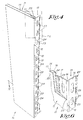
- figure 4 shows in perspective an element according to the invention;
- figure 5, at a larger scale, represents a cross-section according to line V-V in figure 4;
- figure 6, at a larger scale, represents the part indicated by F6 in figure 4, whereby the material of the plate is cut off partially;
- figures 7 and 8 represent how the element from figure 4 is manufactured;
- figure 9, at a larger scale, represents the part indicated by F9 in figure 8, in still a further step of manufacturing;
- figures 10 and 11 represent how the element from figure 4 is applied for finishing a reveal;
- figure 12 represents how a column can be covered by means of elements according to the invention.
- As represented in figures 1 to 3, a reveal 1, in other words, the lateral face of a
wall 2 around awindow 3 or such, is finished in a traditional manner by first, as represented in figures 1 and 2, fixing acorner profile 4 by means of a quantity ofgypsum plaster 5, or in any other manner, and covering thewindow 3 by means of afilm 6 or such, as a protection against spoiling, and subsequently, after thecorner profile 4 is fixed sufficiently by the hardening of thegypsum plaster 5, plastering the reveal 1 as well as thewall side 7 in a classical manner. - During plastering, the
corner profile 4 is used as a guide for smoothing the gypsum plaster 8. It is obvious that at the location of the reveal 1, there is only one guide and that this traditional technique consequently has the disadvantage that it is rather difficult to realize a straight line 9 at thewindow 3. - Another disadvantage consists in that the
window 3 has to be protected by means of afilm 6, or at least a tape, which, as already mentioned in the introduction, is time-consuming, in respect to application as well as removal. - The present invention aims at an element with which a narrow wall part, such as the aforementioned reveal 1, can easily be finished during the realization of plaster works.
- In figures 4 to 6, a preferred form of embodiment of
such element 10 is represented. - This
element 10 consists of a strip-shaped plate 11 for covering the wall part to be finished, whereby thisplate 11, in this case at onelongitudinal edge 12, is provided with an auxiliary part for realizing a corner, which auxiliary part in this case is formed by acorner profile 13 extending in the longitudinal direction of theplate 11. - As represented, the
plate 11 preferably consists of a cardboard-covered gypsum plaster board, in other words, a plate with acore 14 of gypsum or similar and two top layers 15-16 of cardboard. - The
corner profile 13 preferably consists of metal, more particularly stainless and/or galvanized steel. According to the invention, it is, however, not excluded to realize it in other materials, such as, for example, synthetic material. - The
corner profile 13 may be fixed at theplate 11 with oneleg 17 in theplate 11 itself. - The
second leg 18 forms a fixation- and/or adherence flange which extends at an angle in respect to theplate 11 and which can cooperate with plaster work. - In cross-section, the
legs - The
corner profile 13 shows aportion 19 defining a corner edge, more particularly aportion 19 adjoining against the prolongation of thesurface 20 of theplate 11. - The
portion 19 preferably is realized bead-shaped, such that thereby a small rounding at the location of the corner to be realized is obtained. - The
corner profile 13 preferably is fixed at theplate 11 in the manner as represented in figures 7 to 9. - First of all, as represented in figure 7, a
groove 21 is realized in thelongitudinal edge 12 of theplate 11, preferably by means of a milling process. - Subsequently, the
corner profile 13 is accurately positioned in thegroove 21 and fixed therein by means of anadherence agent 22. Hereby, thisadherence agent 22 can first be applied in thegroove 21, after which thecorner profile 13, before theadherence agent 22 has hardened, is pressed on therein. Theadherence agent 22 preferably consists of glue, but it is not excluded to apply other materials to this aim, such as any other hardening filling matter. - As represented in figure 6, the
legs corner profile 13 preferably are provided with means offering a better adherence, on one hand, in theadherence agent 22 and, on the other hand, in the plaster work to be realized subsequently, which means in the example consist ofopenings 23 as well as profiled edges 24. - It is noted that the
groove 21 in the aforementioned first step is realized preferably such that, when thecorner profile 13 is pressed with theround portion 19 against thelongitudinal edge 12 and also is pressed on in such a manner that, as represented in figure 8, at the locations A and B a contact with the opposed sides of thegroove 21 is made, thiscorner profile 13 is situated in correct position, in other words, theportion 19 is brought precisely to equal height with thesurface 20. - It is noted that the inclined implantation of the
leg 17, as well as the fact that thegroove 21 is provided in theplate 11 in an inclined manner, contributes to the fact that thecorner profile 13 is situated particularly solid in theplate 11, even with a tension load according to the direction in the plane of theplate 11 and perpendicular to thelongitudinal edge 12. - The small open joint between the
portion 19 and thelongitudinal edge 12 of theplate 11 can eventually be filled with a fillingagent 25, as represented in figure 9. Preferably, to this aim a flexible joint filler will be used. - It is noted that the
element 10 preferably is realized as a prefabricated element, more particularly an element which is composed before being placed, as described hereafter, against the wall part to be finished. - Although it is not excluded according to the invention to realize the
element 10 at site on the building ground, if there is a suitable milling apparatus or similar, the prefabricated element preferably shall be realized factory-built. - Figures 10 and 11 represent how a reveal 1 is realized by means of an
element 10 according to the invention. - First, the
plate 11 is sawn or cut to size. It is noted that theelements 10 can be fabricated and commercialized with different standard widths, such that, by choosing the just width, theelement 10 only has to be sawn or cut to the right length. - Subsequently, the
element 10 brought to size is fixed against therough surface 26 of the reveal by means of a quantity ofwet gypsum 27 or any other adherence substance, such as represented in figure 10. It is obvious that the window profiles or the window panes of thewindow 3 hereby not necessarily will have to be covered by tape or similar, as by the, so to speak, "dry" finishing of the reveals 1, the risk of spoiling is practically nonexistent. - It is also obvious that, as a result of the
plate 11 being straight, always a straight line 9 at the location of thewindow 3 is obtained by itself. - When the
gypsum 27 has hardened sufficiently, one may immediately start with plastering thewall side 7, whereby, for smoothing theplaster 28, thecorner profile 13 is used as a guide. As represented in figure 11, theleg 18 hereby is completely embedded in theplaster 28, as a result of which a solid corner connection between theplate 11 and theclassical plaster 28 is realized. - Between the
plate 11 and thewindow 3, eventually a small joint may be left which can be filled with an elastic joint filler. - It is noted that the finishing of reveals 1 in this manner is considerably easier than in the case of traditional plaster work. The finishing of the reveals 1 then does not necessarily have to be performed by skilled stuccoers but can also be easily realized by, for example, the persons applying the
window 3, or by less skilled do-it-yourselfers. - The
element 10 can be realized in different variants while still remaining within the scope of the invention. So, for example, does the aforementioned auxiliary part for realizing the corner not necessarily have to consist of acorner profile 13. This auxiliary part, for example, may also be formed of a profile or another element which exclusively offers an edge reinforcement at thelongitudinal edge 12 of theplate 11, without the presence of theaforementioned leg 18. - Instead of using a fixation or adherence flange in the form of a
leg 18 of acorner profile 13, use can also be made of other adherence means, or such adherence means even may be omitted. Another form of possible adherence means, for example, is a net or a fleece which is fixed at theplate 11 and which is folded around the corner when finishing the reveal 1 and is plastered into theplaster work 28. - The auxiliary part preferably extends continuously over the
longitudinal edge 12. However, it is not excluded to work, according to a variant, with interrupted or partially interruped auxiliary parts. So, for example, acorner profile 13 might be used, the legs 17-18 of which, with well-defined interstices, for example, every centimeter, are cut in transverse direction up to theportion 19 forming the actual corner, in such a manner that, when the cardboard of the cardboard-covered gypsum plaster board is cut exactly at the height of such a cut, theelement 10, by folding theplate 11, can simply be broken in two. Hereby, theportion 19 at this height will break. Eventually, it is also possible to simply cut thisportion 19 previously by means of nipper pliers. - The aforegoing allows to cut the
element 10 easily to any length, without having to saw thecorner profile 13 over its entire cross-section. - Possibly, the
plate 11 may consist of pure gypsum or be covered by cardboard on only one side. - Possibly, it can be provided at its rear side with ribs or similar, as a result of which the plate 1 is reinforced and a better adherence in the
gypsum 27 or in another adherence agent is obtained during application. - The
plate 11 possibly can also be provided at bothlongitudinal edges corner profile 13, as a result of whichelements 30 are obtained with which, as represented in figure 12, a covering around a column 31 or similar can be realized. Hereby,such element 30 is provided at two sides of the column 31, after which the other sides can be finished by means ofclassical plaster work 32. - The present invention is in no way limited to the forms of embodiment described by way of example and represented in the figures, on the contrary may such element for finishing a narrow wall part, the method for manufacturing such element, and the method for realizing the covering of a reveal by means of such element be realized in different variants while still remaining within the scope of the invention as defined by the appended claims.
Claims (18)
- Element for finishing a narrow wall part when realising plaster work, more particularly a reveal (1) or a column side, this wall part ,comprising a corner, the element (10-30) consisting of a strip-shaped plate (11) for covering the wall part to be finished, said plate (11) being provided at least at one longitudinal edge side (12) with an auxiliary part extending in longitudinal direction along said edge for realising a corner of the finished wall part, the auxiliary part being formed as a corner profile (13), characterised in that the auxiliary part is provided with a portion (19) defining a corner edge of the finished corner to be realised and with two legs (17-18), wherein a first leg (17) is intended for fixation into a groove (21) in the edge side (12) of the plate (11), and the other leg (18) extends from the plate and is intended for fixation into plaster work (28-32) applied on the wall part used for finishing the wall part (7) on the adjacent side of the corner of the wall part to be finished.
- - Element according to claim 1, characterized in that the auxiliary part is provided with a flange, more particularly a fixation and/or adherence flange extending at an angle in respect to the plate (11).
- - Element according to claim 2, characterized in that the flange is provided with means which guarantee for a good adherence in plaster work (28-32), such as openings (23) or profiled edges (24) which are formed at the aforementioned flange.
- - Element according to any of the preceding claims, characterized in that the corner profile (13) is provided with one leg (17) in a groove (21) in the plate (11) and is attached in this groove (21) by means of an adherence agent (22), such as glue, a filling agent or similar.
- Element according to any of the preceding claims, characterized in that the leg (17) of the corner profile (13) fixed in the plate (11) is provided in this plate (11) in an inclined manner, with respect to the exterior surface of the plate (11).
- - Element according to any of the preceding claims, characterized in that said portion (19) defining a corner edge, is situated such that it adjoins against the prolongation of the exterior surface of the aforementioned plate (11).
- - Element according to any of the preceding claims, characterized in that the portion (19) of the auxiliary part forms a rounding at the location of the corner.
- - Element according to claims 4 and 7, characterized in that between the longitudinal edge (12-29) of the plate (11) and the aforementioned portion (19), a joint is present and that this joint is filled with a filling agent (25).
- - Element according to any of the preceding claims, characterized in that the plate (11) substantially consists of gypsum, preferably a cardboard-covered gypsum plaster board.
- - Element according to any of the preceding claims, characterized in that the aforementioned auxiliary part, more particularly the aforementioned corner profile (13), consists of metal.
- - Element according to any of the preceding claims, characterized in that it is realized as a prefabricated element (10-30)
- - Element according to any of the preceding claims, characterized in that it is intended for finishing a reveal (1) and that the plate (11) is provided at only one longitudinal edge (12) with said auxiliary part.
- Element according to any of the claims 1 to 11, characterised in that it is intended for finishing a wall side of a column (31) with two corners and that the plate (11) is provided at both longitudinal edges (12-29) on each of said corners of the plate with auxiliary parts covering said corners of the column to be finished.
- - Method for manufacturing an element according to any of the preceding claims, characterized in that it consists in forming a strip-shaped plate (11) made of cardboard-covered gypsum plaster board; providing a groove (21) in at least one longitudinal narrow side of the plate (11); and providing and attaching a leg of a corner profile (13) in a respective groove (21).
- - Method according to claim 14, characterized in that each respective corner profile (13) is attached in the groove (21) by means of glue.
- - Method according to claim 14 or 15, characterized in that a corner profile (13) is applied consisting of two legs (17-18) with a round portion (19) in between which forms a corner edge, and that the joint between the longitudinal edge (12-29) of the plate (11) and the aforementioned portion (19) is filled with a filling agent (25).
- - Method according to any of the claims 14 to 16, characterized in tht a corner profile (13) is applied which is provided with a portion (19) forming a corner edge and that each respective groove (21) is provided in the plate (11) such that, when the corner profile (13) is pressed on with its respective leg (17) in the groove (21), in such a manner that contact is made with the respective sides of the groove (21) at two locations (A-B), this corner profile (13) is in correct position, in other words, the aforementioned portion (19) is located precisely at the same height as the exterior surface (20) of the plate (11).
- - Method for finishing a reveal, whereby use is made of an element according to claims 12, characterized in that it consists in bringing the element (10) to the required length and width; providing a quantity of adherence substance, more particularly gypsum (27), on the unfinished reveal (1); pressing and positioning the aforementioned element (10) against this adherence substance; and, after the aforementioned adherence substance has hardened sufficiently, plastering the wall part (7) adjoining perpendicular to the reveal (1), whereby the aforementioned element (10), more particularly the pertaining auxiliary part, is used as a guide for plastering.
Applications Claiming Priority (2)
| Application Number | Priority Date | Filing Date | Title |
|---|---|---|---|
| BE9900006 | 1999-01-06 | ||
| BE9900006A BE1012377A3 (en) | 1999-01-06 | 1999-01-06 | ELEMENT FOR FINISHING A narrow wall part when realizing AN PLASTERING AND METHOD FOR PRODUCING SUCH ELEMENT. |
Publications (2)
| Publication Number | Publication Date |
|---|---|
| EP1018582A1 EP1018582A1 (en) | 2000-07-12 |
| EP1018582B1 true EP1018582B1 (en) | 2006-05-10 |
Family
ID=3891681
Family Applications (1)
| Application Number | Title | Priority Date | Filing Date |
|---|---|---|---|
| EP00200025A Expired - Lifetime EP1018582B1 (en) | 1999-01-06 | 2000-01-04 | Element for finishing a narrow wall part when realizing plaster work and method for manufacturing such element |
Country Status (5)
| Country | Link |
|---|---|
| EP (1) | EP1018582B1 (en) |
| AT (1) | ATE325929T1 (en) |
| BE (1) | BE1012377A3 (en) |
| DE (1) | DE60027802T2 (en) |
| NO (1) | NO20000034L (en) |
Families Citing this family (2)
| Publication number | Priority date | Publication date | Assignee | Title |
|---|---|---|---|---|
| GB2436569A (en) * | 2006-03-30 | 2007-10-03 | Matthew Lee | Reveal cover |
| BE1025362B1 (en) * | 2017-12-19 | 2019-01-30 | Jansen Products, Naamloze Vennootschap | Element for finishing a wall part in a plastering and method for manufacturing it |
Family Cites Families (5)
| Publication number | Priority date | Publication date | Assignee | Title |
|---|---|---|---|---|
| US2725607A (en) * | 1952-10-28 | 1955-12-06 | Angeles Metal Trim Co | Wallboard trim |
| US3287867A (en) * | 1964-01-03 | 1966-11-29 | Loyd P Aton | Stair nosing |
| DE3218533C2 (en) * | 1982-05-17 | 1985-04-11 | Oskar 6620 Völklingen Adam | Reveal shell for window or door reveals |
| DE8810264U1 (en) * | 1988-08-12 | 1988-09-29 | Zahner, Heinz, 8808 Herrieden | Connecting corner strip |
| US5243797A (en) * | 1992-03-20 | 1993-09-14 | Trim-Tex, Inc. | Drywall finishing and masking accessory |
-
1999
- 1999-01-06 BE BE9900006A patent/BE1012377A3/en not_active IP Right Cessation
-
2000
- 2000-01-04 DE DE60027802T patent/DE60027802T2/en not_active Expired - Fee Related
- 2000-01-04 AT AT00200025T patent/ATE325929T1/en not_active IP Right Cessation
- 2000-01-04 EP EP00200025A patent/EP1018582B1/en not_active Expired - Lifetime
- 2000-01-05 NO NO20000034A patent/NO20000034L/en not_active Application Discontinuation
Also Published As
| Publication number | Publication date |
|---|---|
| NO20000034D0 (en) | 2000-01-05 |
| EP1018582A1 (en) | 2000-07-12 |
| BE1012377A3 (en) | 2000-10-03 |
| ATE325929T1 (en) | 2006-06-15 |
| NO20000034L (en) | 2000-07-07 |
| DE60027802T2 (en) | 2007-03-08 |
| DE60027802D1 (en) | 2006-06-14 |
Similar Documents
| Publication | Publication Date | Title |
|---|---|---|
| US5138810A (en) | Corneraide device and method | |
| CA2072005C (en) | Predecorated wallboard joint and method of joining predecorated wallboards to form a concealed joint | |
| US5269861A (en) | Structure and method for repair of sheetrock walls | |
| SK101894A3 (en) | Plastering and lining strip for window stiles, doors stiles and the like for the joint with the plastering | |
| US5925204A (en) | Method for repairing a damaged portion of wallboard | |
| US4122222A (en) | Laminate and method for drywall holes and joints | |
| DE3527507C2 (en) | ||
| CA2464079A1 (en) | Window wrap | |
| EP1018582A1 (en) | Element for finishing a narrow wall part when realizing plaster work and method for manufacturing such element | |
| GB2323394A (en) | Mortarless brick walls | |
| US1818704A (en) | Wall construction | |
| JP3918353B2 (en) | Out corner pillar | |
| JPH0949305A (en) | Interior finish wall | |
| US4136147A (en) | Method of applying fire-proofing material to elongate structural member | |
| JP2000303652A (en) | Joint make-up method, in-corner make-up method, and architectural board for implementing the method | |
| JP2022092261A (en) | Joint construction method | |
| JP2003129587A (en) | Refractory plate, and decorative refractory cover structure for steel column using the same | |
| NL2035066B1 (en) | ELEMENT FOR FINISHING A WALL SECTION | |
| JP3249385U (en) | Decorative film application spatula | |
| EP0940521B1 (en) | Wire bead for plaster, stucco and the like | |
| JPH0242823Y2 (en) | ||
| JP2995265B1 (en) | Outer corner material and method of treating inner corner of indoor wall using the same | |
| WO2026102488A1 (en) | Caulking tape system and method for controlled joint formation | |
| AU2002100754B4 (en) | Termite control system | |
| BE1031692A1 (en) | Element for finishing a wall section |
Legal Events
| Date | Code | Title | Description |
|---|---|---|---|
| PUAI | Public reference made under article 153(3) epc to a published international application that has entered the european phase |
Free format text: ORIGINAL CODE: 0009012 |
|
| AK | Designated contracting states |
Kind code of ref document: A1 Designated state(s): AT BE CH CY DE DK ES FI FR GB GR IE IT LI LU MC NL PT SE |
|
| AX | Request for extension of the european patent |
Free format text: AL;LT;LV;MK;RO;SI |
|
| 17P | Request for examination filed |
Effective date: 20010109 |
|
| AKX | Designation fees paid |
Free format text: AT BE CH CY DE DK ES FI FR GB GR IE IT LI LU MC NL PT SE |
|
| 17Q | First examination report despatched |
Effective date: 20031127 |
|
| GRAP | Despatch of communication of intention to grant a patent |
Free format text: ORIGINAL CODE: EPIDOSNIGR1 |
|
| GRAS | Grant fee paid |
Free format text: ORIGINAL CODE: EPIDOSNIGR3 |
|
| GRAA | (expected) grant |
Free format text: ORIGINAL CODE: 0009210 |
|
| AK | Designated contracting states |
Kind code of ref document: B1 Designated state(s): AT BE CH CY DE DK ES FI FR GB GR IE IT LI LU MC NL PT SE |
|
| PG25 | Lapsed in a contracting state [announced via postgrant information from national office to epo] |
Ref country code: IT Free format text: LAPSE BECAUSE OF FAILURE TO SUBMIT A TRANSLATION OF THE DESCRIPTION OR TO PAY THE FEE WITHIN THE PRESCRIBED TIME-LIMIT;WARNING: LAPSES OF ITALIAN PATENTS WITH EFFECTIVE DATE BEFORE 2007 MAY HAVE OCCURRED AT ANY TIME BEFORE 2007. THE CORRECT EFFECTIVE DATE MAY BE DIFFERENT FROM THE ONE RECORDED. Effective date: 20060510 Ref country code: FI Free format text: LAPSE BECAUSE OF FAILURE TO SUBMIT A TRANSLATION OF THE DESCRIPTION OR TO PAY THE FEE WITHIN THE PRESCRIBED TIME-LIMIT Effective date: 20060510 Ref country code: CH Free format text: LAPSE BECAUSE OF FAILURE TO SUBMIT A TRANSLATION OF THE DESCRIPTION OR TO PAY THE FEE WITHIN THE PRESCRIBED TIME-LIMIT Effective date: 20060510 Ref country code: AT Free format text: LAPSE BECAUSE OF FAILURE TO SUBMIT A TRANSLATION OF THE DESCRIPTION OR TO PAY THE FEE WITHIN THE PRESCRIBED TIME-LIMIT Effective date: 20060510 Ref country code: LI Free format text: LAPSE BECAUSE OF FAILURE TO SUBMIT A TRANSLATION OF THE DESCRIPTION OR TO PAY THE FEE WITHIN THE PRESCRIBED TIME-LIMIT Effective date: 20060510 |
|
| REG | Reference to a national code |
Ref country code: GB Ref legal event code: FG4D |
|
| REG | Reference to a national code |
Ref country code: CH Ref legal event code: EP |
|
| REF | Corresponds to: |
Ref document number: 60027802 Country of ref document: DE Date of ref document: 20060614 Kind code of ref document: P |
|
| REG | Reference to a national code |
Ref country code: IE Ref legal event code: FG4D |
|
| PG25 | Lapsed in a contracting state [announced via postgrant information from national office to epo] |
Ref country code: SE Free format text: LAPSE BECAUSE OF FAILURE TO SUBMIT A TRANSLATION OF THE DESCRIPTION OR TO PAY THE FEE WITHIN THE PRESCRIBED TIME-LIMIT Effective date: 20060810 Ref country code: DK Free format text: LAPSE BECAUSE OF FAILURE TO SUBMIT A TRANSLATION OF THE DESCRIPTION OR TO PAY THE FEE WITHIN THE PRESCRIBED TIME-LIMIT Effective date: 20060810 |
|
| PG25 | Lapsed in a contracting state [announced via postgrant information from national office to epo] |
Ref country code: ES Free format text: LAPSE BECAUSE OF FAILURE TO SUBMIT A TRANSLATION OF THE DESCRIPTION OR TO PAY THE FEE WITHIN THE PRESCRIBED TIME-LIMIT Effective date: 20060821 |
|
| PG25 | Lapsed in a contracting state [announced via postgrant information from national office to epo] |
Ref country code: PT Free format text: LAPSE BECAUSE OF FAILURE TO SUBMIT A TRANSLATION OF THE DESCRIPTION OR TO PAY THE FEE WITHIN THE PRESCRIBED TIME-LIMIT Effective date: 20061010 |
|
| REG | Reference to a national code |
Ref country code: CH Ref legal event code: PL |
|
| PGFP | Annual fee paid to national office [announced via postgrant information from national office to epo] |
Ref country code: LU Payment date: 20061220 Year of fee payment: 8 |
|
| PGFP | Annual fee paid to national office [announced via postgrant information from national office to epo] |
Ref country code: GB Payment date: 20070118 Year of fee payment: 8 |
|
| PG25 | Lapsed in a contracting state [announced via postgrant information from national office to epo] |
Ref country code: MC Free format text: LAPSE BECAUSE OF NON-PAYMENT OF DUE FEES Effective date: 20070131 |
|
| PGFP | Annual fee paid to national office [announced via postgrant information from national office to epo] |
Ref country code: NL Payment date: 20070131 Year of fee payment: 8 |
|
| PLBE | No opposition filed within time limit |
Free format text: ORIGINAL CODE: 0009261 |
|
| STAA | Information on the status of an ep patent application or granted ep patent |
Free format text: STATUS: NO OPPOSITION FILED WITHIN TIME LIMIT |
|
| 26N | No opposition filed |
Effective date: 20070213 |
|
| EN | Fr: translation not filed | ||
| PG25 | Lapsed in a contracting state [announced via postgrant information from national office to epo] |
Ref country code: DE Free format text: LAPSE BECAUSE OF NON-PAYMENT OF DUE FEES Effective date: 20070801 |
|
| PG25 | Lapsed in a contracting state [announced via postgrant information from national office to epo] |
Ref country code: GR Free format text: LAPSE BECAUSE OF FAILURE TO SUBMIT A TRANSLATION OF THE DESCRIPTION OR TO PAY THE FEE WITHIN THE PRESCRIBED TIME-LIMIT Effective date: 20060811 Ref country code: FR Free format text: LAPSE BECAUSE OF FAILURE TO SUBMIT A TRANSLATION OF THE DESCRIPTION OR TO PAY THE FEE WITHIN THE PRESCRIBED TIME-LIMIT Effective date: 20070309 |
|
| GBPC | Gb: european patent ceased through non-payment of renewal fee |
Effective date: 20080104 |
|
| NLV4 | Nl: lapsed or anulled due to non-payment of the annual fee |
Effective date: 20080801 |
|
| PG25 | Lapsed in a contracting state [announced via postgrant information from national office to epo] |
Ref country code: NL Free format text: LAPSE BECAUSE OF NON-PAYMENT OF DUE FEES Effective date: 20080801 |
|
| PG25 | Lapsed in a contracting state [announced via postgrant information from national office to epo] |
Ref country code: FR Free format text: LAPSE BECAUSE OF FAILURE TO SUBMIT A TRANSLATION OF THE DESCRIPTION OR TO PAY THE FEE WITHIN THE PRESCRIBED TIME-LIMIT Effective date: 20060510 |
|
| PG25 | Lapsed in a contracting state [announced via postgrant information from national office to epo] |
Ref country code: GB Free format text: LAPSE BECAUSE OF NON-PAYMENT OF DUE FEES Effective date: 20080104 |
|
| PG25 | Lapsed in a contracting state [announced via postgrant information from national office to epo] |
Ref country code: CY Free format text: LAPSE BECAUSE OF FAILURE TO SUBMIT A TRANSLATION OF THE DESCRIPTION OR TO PAY THE FEE WITHIN THE PRESCRIBED TIME-LIMIT Effective date: 20060510 |
|
| PGFP | Annual fee paid to national office [announced via postgrant information from national office to epo] |
Ref country code: IE Payment date: 20071221 Year of fee payment: 9 |
|
| PG25 | Lapsed in a contracting state [announced via postgrant information from national office to epo] |
Ref country code: IE Free format text: LAPSE BECAUSE OF NON-PAYMENT OF DUE FEES Effective date: 20090105 |
|
| PG25 | Lapsed in a contracting state [announced via postgrant information from national office to epo] |
Ref country code: LU Free format text: LAPSE BECAUSE OF NON-PAYMENT OF DUE FEES Effective date: 20080104 |
|
| PGFP | Annual fee paid to national office [announced via postgrant information from national office to epo] |
Ref country code: BE Payment date: 20181221 Year of fee payment: 20 |
|
| REG | Reference to a national code |
Ref country code: BE Ref legal event code: MK Effective date: 20200104 |