EP1018195B1 - Optical amplifier with actively controlled spectral gain - Google Patents
Optical amplifier with actively controlled spectral gain Download PDFInfo
- Publication number
- EP1018195B1 EP1018195B1 EP98941880A EP98941880A EP1018195B1 EP 1018195 B1 EP1018195 B1 EP 1018195B1 EP 98941880 A EP98941880 A EP 98941880A EP 98941880 A EP98941880 A EP 98941880A EP 1018195 B1 EP1018195 B1 EP 1018195B1
- Authority
- EP
- European Patent Office
- Prior art keywords
- optical
- gain
- optical amplifier
- wavelength
- filter
- Prior art date
- Legal status (The legal status is an assumption and is not a legal conclusion. Google has not performed a legal analysis and makes no representation as to the accuracy of the status listed.)
- Expired - Lifetime
Links
Images


Classifications
-
- G—PHYSICS
- G02—OPTICS
- G02B—OPTICAL ELEMENTS, SYSTEMS OR APPARATUS
- G02B6/00—Light guides; Structural details of arrangements comprising light guides and other optical elements, e.g. couplings
- G02B6/02—Optical fibres with cladding with or without a coating
-
- H—ELECTRICITY
- H01—ELECTRIC ELEMENTS
- H01S—DEVICES USING THE PROCESS OF LIGHT AMPLIFICATION BY STIMULATED EMISSION OF RADIATION [LASER] TO AMPLIFY OR GENERATE LIGHT; DEVICES USING STIMULATED EMISSION OF ELECTROMAGNETIC RADIATION IN WAVE RANGES OTHER THAN OPTICAL
- H01S3/00—Lasers, i.e. devices using stimulated emission of electromagnetic radiation in the infrared, visible or ultraviolet wave range
- H01S3/05—Construction or shape of optical resonators; Accommodation of active medium therein; Shape of active medium
- H01S3/06—Construction or shape of active medium
- H01S3/063—Waveguide lasers, i.e. whereby the dimensions of the waveguide are of the order of the light wavelength
- H01S3/067—Fibre lasers
- H01S3/06795—Fibre lasers with superfluorescent emission, e.g. amplified spontaneous emission sources for fibre laser gyrometers
-
- H—ELECTRICITY
- H01—ELECTRIC ELEMENTS
- H01S—DEVICES USING THE PROCESS OF LIGHT AMPLIFICATION BY STIMULATED EMISSION OF RADIATION [LASER] TO AMPLIFY OR GENERATE LIGHT; DEVICES USING STIMULATED EMISSION OF ELECTROMAGNETIC RADIATION IN WAVE RANGES OTHER THAN OPTICAL
- H01S3/00—Lasers, i.e. devices using stimulated emission of electromagnetic radiation in the infrared, visible or ultraviolet wave range
- H01S3/10—Controlling the intensity, frequency, phase, polarisation or direction of the emitted radiation, e.g. switching, gating, modulating or demodulating
- H01S3/13—Stabilisation of laser output parameters, e.g. frequency or amplitude
- H01S3/1301—Stabilisation of laser output parameters, e.g. frequency or amplitude in optical amplifiers
- H01S3/13013—Stabilisation of laser output parameters, e.g. frequency or amplitude in optical amplifiers by controlling the optical pumping
-
- H—ELECTRICITY
- H04—ELECTRIC COMMUNICATION TECHNIQUE
- H04B—TRANSMISSION
- H04B10/00—Transmission systems employing electromagnetic waves other than radio-waves, e.g. infrared, visible or ultraviolet light, or employing corpuscular radiation, e.g. quantum communication
- H04B10/29—Repeaters
- H04B10/291—Repeaters in which processing or amplification is carried out without conversion of the main signal from optical form
- H04B10/293—Signal power control
- H04B10/294—Signal power control in a multiwavelength system, e.g. gain equalisation
- H04B10/2941—Signal power control in a multiwavelength system, e.g. gain equalisation using an equalising unit, e.g. a filter
-
- H—ELECTRICITY
- H04—ELECTRIC COMMUNICATION TECHNIQUE
- H04B—TRANSMISSION
- H04B10/00—Transmission systems employing electromagnetic waves other than radio-waves, e.g. infrared, visible or ultraviolet light, or employing corpuscular radiation, e.g. quantum communication
- H04B10/29—Repeaters
- H04B10/291—Repeaters in which processing or amplification is carried out without conversion of the main signal from optical form
- H04B10/293—Signal power control
- H04B10/294—Signal power control in a multiwavelength system, e.g. gain equalisation
- H04B10/296—Transient power control, e.g. due to channel add/drop or rapid fluctuations in the input power
-
- H—ELECTRICITY
- H01—ELECTRIC ELEMENTS
- H01S—DEVICES USING THE PROCESS OF LIGHT AMPLIFICATION BY STIMULATED EMISSION OF RADIATION [LASER] TO AMPLIFY OR GENERATE LIGHT; DEVICES USING STIMULATED EMISSION OF ELECTROMAGNETIC RADIATION IN WAVE RANGES OTHER THAN OPTICAL
- H01S2301/00—Functional characteristics
- H01S2301/04—Gain spectral shaping, flattening
-
- H—ELECTRICITY
- H01—ELECTRIC ELEMENTS
- H01S—DEVICES USING THE PROCESS OF LIGHT AMPLIFICATION BY STIMULATED EMISSION OF RADIATION [LASER] TO AMPLIFY OR GENERATE LIGHT; DEVICES USING STIMULATED EMISSION OF ELECTROMAGNETIC RADIATION IN WAVE RANGES OTHER THAN OPTICAL
- H01S3/00—Lasers, i.e. devices using stimulated emission of electromagnetic radiation in the infrared, visible or ultraviolet wave range
- H01S3/05—Construction or shape of optical resonators; Accommodation of active medium therein; Shape of active medium
- H01S3/06—Construction or shape of active medium
- H01S3/063—Waveguide lasers, i.e. whereby the dimensions of the waveguide are of the order of the light wavelength
- H01S3/067—Fibre lasers
- H01S3/06754—Fibre amplifiers
- H01S3/06758—Tandem amplifiers
-
- H—ELECTRICITY
- H01—ELECTRIC ELEMENTS
- H01S—DEVICES USING THE PROCESS OF LIGHT AMPLIFICATION BY STIMULATED EMISSION OF RADIATION [LASER] TO AMPLIFY OR GENERATE LIGHT; DEVICES USING STIMULATED EMISSION OF ELECTROMAGNETIC RADIATION IN WAVE RANGES OTHER THAN OPTICAL
- H01S3/00—Lasers, i.e. devices using stimulated emission of electromagnetic radiation in the infrared, visible or ultraviolet wave range
- H01S3/10—Controlling the intensity, frequency, phase, polarisation or direction of the emitted radiation, e.g. switching, gating, modulating or demodulating
- H01S3/10007—Controlling the intensity, frequency, phase, polarisation or direction of the emitted radiation, e.g. switching, gating, modulating or demodulating in optical amplifiers
- H01S3/10015—Controlling the intensity, frequency, phase, polarisation or direction of the emitted radiation, e.g. switching, gating, modulating or demodulating in optical amplifiers by monitoring or controlling, e.g. attenuating, the input signal
-
- H—ELECTRICITY
- H01—ELECTRIC ELEMENTS
- H01S—DEVICES USING THE PROCESS OF LIGHT AMPLIFICATION BY STIMULATED EMISSION OF RADIATION [LASER] TO AMPLIFY OR GENERATE LIGHT; DEVICES USING STIMULATED EMISSION OF ELECTROMAGNETIC RADIATION IN WAVE RANGES OTHER THAN OPTICAL
- H01S3/00—Lasers, i.e. devices using stimulated emission of electromagnetic radiation in the infrared, visible or ultraviolet wave range
- H01S3/10—Controlling the intensity, frequency, phase, polarisation or direction of the emitted radiation, e.g. switching, gating, modulating or demodulating
- H01S3/10007—Controlling the intensity, frequency, phase, polarisation or direction of the emitted radiation, e.g. switching, gating, modulating or demodulating in optical amplifiers
- H01S3/10023—Controlling the intensity, frequency, phase, polarisation or direction of the emitted radiation, e.g. switching, gating, modulating or demodulating in optical amplifiers by functional association of additional optical elements, e.g. filters, gratings, reflectors
- H01S3/1003—Controlling the intensity, frequency, phase, polarisation or direction of the emitted radiation, e.g. switching, gating, modulating or demodulating in optical amplifiers by functional association of additional optical elements, e.g. filters, gratings, reflectors tunable optical elements, e.g. acousto-optic filters, tunable gratings
-
- H—ELECTRICITY
- H01—ELECTRIC ELEMENTS
- H01S—DEVICES USING THE PROCESS OF LIGHT AMPLIFICATION BY STIMULATED EMISSION OF RADIATION [LASER] TO AMPLIFY OR GENERATE LIGHT; DEVICES USING STIMULATED EMISSION OF ELECTROMAGNETIC RADIATION IN WAVE RANGES OTHER THAN OPTICAL
- H01S3/00—Lasers, i.e. devices using stimulated emission of electromagnetic radiation in the infrared, visible or ultraviolet wave range
- H01S3/30—Lasers, i.e. devices using stimulated emission of electromagnetic radiation in the infrared, visible or ultraviolet wave range using scattering effects, e.g. stimulated Brillouin or Raman effects
- H01S3/302—Lasers, i.e. devices using stimulated emission of electromagnetic radiation in the infrared, visible or ultraviolet wave range using scattering effects, e.g. stimulated Brillouin or Raman effects in an optical fibre
-
- H—ELECTRICITY
- H04—ELECTRIC COMMUNICATION TECHNIQUE
- H04B—TRANSMISSION
- H04B2210/00—Indexing scheme relating to optical transmission systems
- H04B2210/003—Devices including multiple stages, e.g., multi-stage optical amplifiers or dispersion compensators
Definitions
- the present invention relates to an optical amplifier, more specifically to an optical amplifier capable of adjusting the gain curve by actively controlling the spectral gain of the optical amplifier.
- Gain-flattening of optical amplifiers has been a hot topic of research since it is directly related to the transmission capacity of WDM optical communication systems.
- passive wavelength filters with fixed loss curves have been used for the gain-flattening of optical amplifiers.
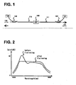
- FIG. 1 shows a schematic of a dual-stage EDFA(Erbium Doped fiber Amplifier) employing a passive gain-flattening filter according to the prior art.
- a passive gain-flattening wavelength filter 100 is inserted between the first EDF(Erbium Doped Fiber) 110 and the second EDF 111.
- Fiber gratings or thin-film filters are generally used as passive gain-flattening filter 100.
- the length, doping concentration or the like of the respective EDFs as well as the pumping direction or power of the pumping lights 120 and 121 may differ depending on the situations.
- optical signals 130 and 131 enter the EDFA bidirectionally, but occasionally optical signals may unidirectionally enter the EDFA.
- optical signals are amplified in the first and second EDFs 110 and 111 after passing through WDM couplers 140 and 141.
- the dual-stage EDFA shown in FIG. 1 provides superior gain and noise characteristics to a single-stage EDFA in spite of the optical loss resulting from wavelength filter 100.
- an additional optical isolator may be provided beside wavelength filter 100 to suppress backward spontaneous emission.
- the gain variation of a conventional EDFA is more than a few dB in the wavelength region of interest, typically over 30 nm around 1550 nm.
- FIG. 2 schematically shows the gain profiles across the 1500 - 1600nm region of the spectrum before and after the gain flattening using an appropriate wavelength filter.
- Gain-flattening is very important for the WDM optical communication systems.
- the operating conditions of the optical amplifier such as input signal power, gain, pumping power, temperature and the like are changed, flat gain profile can not be obtained since the gain characteristics of the EDF varies.
- Such changes in the operating conditions may arise from the reconfiguration or degradation of the optical communication networks. Therefore, to realize stable and flexible WDM optical communication systems, intelligent optical amplifiers are needed which can actively cope with various changes in operating conditions.
- the optical amplifier utilizing Raman nonlinear effect in an optical fiber has widely been studied along with the EDFA.
- the basic configuration of the Raman optical amplifier is similar to that of the EDFA shown in FIG. 1 but it employs a telecommunication grade fiber, a special fiber with a numerical aperture("NA") giving high Raman efficiency or a phosphosilicate based fiber with large Raman wavelength shift.
- the Raman optical amplifier is pumped by a high power laser having more than a few hundred mW pump power and a wavelength that is determined by the specific Raman wavelength shift of the fiber used.
- the wavelength range of the Raman gain curve is about 100nm wider than that of a common EDF but the gain variation is too large for the use of the WDM optical communication systems. Therefore, even in the case of the Raman optical amplifier, intelligent optical amplifiers are needed which can actively cope with various changes in operating conditions to achieve gain-flattening.
- the document EP 0 713 273 A2 describes an optical fiber amplifier which comprises a pre-amp 2 and a post-amp 3, which are connected in series, a photocoupler 4, a long wave pass filter (LWPF) 5 and an LWPF controller 6.
- the LWPF 5 is put on between the pre-amp 2 and the post-amp 3, and its cutoff wavelength can be adjustable.
- the LWPF controller 6 detects an input signal power of the input light signal and adjusts the cutoff wavelength of the LWPF 5 based on the detected input signal power.
- Gain of light signals which are output from the post-amp 3 are equalized ranging the extensive input signal power and covering wide signal-wavelenghts bands.
- the optical amplifier according to the present invention comprises a length of optical waveguide having a gain medium therein, optical pumping means, optical input means and at least one wavelength tunable filter.
- the gain medium may be composed of the different types of gain optical fibers.
- the wavelength tunable filter is disposed between two different types of gain optical fibers.
- the wavelength tunable filter comprises filter driving means for controlling the loss profile of the tunable filter. Feedback signals calculated from the measured gain curve of the optical amplifier is applied to the filter driving means in order to actively adjust the gain curve.
- the optical amplifier may further comprise temperature detecting means to compensate temperature change in the inside of the optical amplifier.
- the wavelength tunable filter is an all-fiber acousto-optic wavelength filter based on coupling between spatial modes in optical fibers.
- the wavelength tunable filter for the gain-flattening is composed of two devices AOTF1 and AOTF2 connected in series.
- Acoustic wave generators are composed of piezoelectric devices 200 and 201 and acoustic horns 203 and 204.
- the Acoustic wave generators are driven by the alternating electrical signals from filter drivers 210 and 211.
- the generated acoustic wave propagates along single mode optical fibers 220 and 221. When the wavelength of the acoustic wave coincides with the beat length between modes, mode-coupling is induced.
- the acoustic wave propagates along the length of 15cm in the single mode fiber.
- Mode-coupling to the respective cladding modes was achieved by applying three electrical signals generated from singal generators rf1, rf2 and rf3 to piezoelectric device 200.
- the half width half maximum of this filter was 3.3, 4.1 and 4.9nm, respectively.
- the fiber length for inducing mode-coupling was 5cm.
- Mode-coupling to the respective cladding modes(LP11, LP12, LP13) was achieved by applying three electrical signals generated from singal generators rf4, rf5 and rf6 to piezoelectric device 201.
- the half width half maximum of this filter was 8.0, 8.6 and 14.5nm, respectively.
- the maximum response speed mainly depends on the length of the optical fiber.
- two devices AOTF1 and AOTF2 they were 95 ⁇ s and 25 ⁇ s, respectively.
- the first device AOTF1 with narrow linewidth was used in flattening the gain over the 1530nm range, whereas the second device AOTF2 with broad linewidth was used in flattening the gain over the 1555nm range.
- the basic optical loss of two devices due to the connection of optical fibers was less than 0.5dB.
- FIG. 4 shows the configuration of the unidirectional dual-stage optical amplifier employing gain-flattening wavelength tunable filter 300 and signal generator 310 described in FIG. 3 .
- Optical fibers 320 and 321 doped with erbium of about 300ppm concentration exhibit about 2.5dB/m absorption at 1530nm, respectively.
- the first stage optical fiber 320(length: 10m) was pumped with 980nm laser diode 330 to enhance the noise characteristics.
- -10dBm optical signal was pumped with 20mW power at 1550nm, more than 10dB gain as well as more than 4dB noise figure were achieved.
- the second stage optical fiber 321(length: 24m) was pumped with 1480nm laser diode 331.
- an optical isolator 340 was used to suppress the backward spontaneous emission and the effect of reflected signals.
- the two optical fibers have different physical property since at least one parameter of the optical fibers such as core radius, material, doping concentration or length is different from each other.
- optical fibers obtaining optical gain from Raman nonlinear effect or semiconductor optical amplifying media may be used.
- a 1547.4nm DFB(Distributed FeedBack) laser output and LED(Light Emitting Diode) output were input to the above optical amplifier as a saturating signal and a probe light, respectively. Then, the gain and noise figure were measured by detecting the respective intensities of amplified LED light and spontaneous emission using a wavelength analyzer.
- the input probe light power was -27dBm over the range 1520nm to 1570nm, which was adjusted to be higher than that of spontaneous emission by more than 3dB as well as much lower than that(-13 ⁇ -7dBm) of the DFB light for the reduction of measurement error.
- FIG. 5A shows the gain curves before and after the gain flattening when the saturating signal(DFB light) power is -13dBm.
- the gain curve 400 before the gain flattening was obtained when electrical signals are not applied to the filter.
- the gain curve 402 after the gain flattening was obtained by adjusting the loss curve of the filter to minimize the gain variation.
- the gain after the gain flattening approaches a constant value(22dB) over the 35nm range between 1528nm and 1563nm.
- the arrow 410 represents the wavelength of the saturating signal.
- FIG. 5B shows the gain curves 420 and 422 before and after the gain flattening when the saturating signal power is 7dBm. 16dB flat gain was obtained by adjusting the loss curve of the filter.
- FIGS. 6A and 6B show the loss curves of the wavelength tunable filter for two different saturation powers of -13dBm and -7dBm, respectively.
- the wavelength tunable filter is the one used for the optical amplifier according to the first embodiment of the present invention.
- the loss curves 452 and 454 produced by the first and second devices AOTF1, AOTF2 of FIG. 3 were combined to form a total loss curve 450 in log scale.
- the total curve 460 was formed from the loss curves 462 and 464.
- the first and second devices AOTF1 and AOTF2 were used in flattening the gain over the 1530nm and 1555nm ranges, respectively.
- the six arrows indicate the center wavelengths of the notches produced by six alternating electrical signals.
- the frequency and voltage of applied electrical signals were 2.0076MHz; 10.04V, 2.4015MHz; 9.96V, 2.9942MHz; 23.2V, 1.0277MHz; 15V, 1.5453MHz; 9V and 2.3357MHz; 17.2V, when measured with the output impedance of 50 ⁇ .
- they were 2.0078MHz; 4.74V, 2.3989MHz; 7.58V, 2.9938MHz; 14.02V, 1.0348MHz; 20.02V, 1.5391MHz; 13.2V and 2.3375MHz; 15.8V. If the efficiency of the acoustic wave generator is enhanced and an optical fiber having smaller diameter is employed, the drive voltage can be lowered less than 1V.
- the active optical amplifier according to the first embodiment of the present invention can be used to obtain a desired gain curve under various operating conditions unlike the conventional passive optical amplifier.
- the advantage of the active optical amplifier could be validated through the following experiment. In the experiment, the loss curve of the filter as well as the pumping power for the second stage optical fiber were adjusted to obtain 19dBm flat gain when the saturating signal power was 10dBm.
- FIG. 7A shows flattened gain curves at various operating gain levels of the optical amplifier according to the present invention, which is obtained by adjusting the filter.
- FIG. 7B shows gain tilt produced when the filter is not adjusted.
- the curve 500 is a flattened gain curve for the pumping power of 42mW.
- pumping power and filter profile should be readjusted to change the gain of an optical amplifier.
- the curves 502 and 504 are flattened gain curves obtained when the pumping powers are changed to 75mW and 21mW and filter profiles are adjusted to reach the gain levels of 22.5dB and 16dB, respectively.
- the noise figures 510 are less than 5dB over the 35nm range between 1528nm and 1563nm.
- the optical amplifier employing this filter with actively tunable loss curve can produce flattened gain profiles at various gain levels.
- the optical amplifier employing the conventional passive wavelength filter can no more produce flattened gain profiles for the adjustment of gain levels since it is designed to produce flattened gain profiles at a specific gain level.
- FIG. 7B shows the experimental result to demonstrate this problem.
- the filter was adjusted to obtain flattened 19dB gain at the pumping power of 42mW. Then, the pumping power was increased up to 75mW without changing the loss curve of the filter. In this case, the gain 522 increased on the whole, but a gain variation of 3dB was observed over the 35nm range.
- the gain 524 decreased with a gain variation of about 4dB.
- Such gain tilts were expected to be a problem of the optical amplifier employing passive wavelength filters, exhibiting the limitation of the convention optical amplifier applications.
- a gain detection system that can determine whether the measured gain curve coincides with a desired gain profile is required to realize a self-adjusting optical amplifier in spite of the changes in operating conditions.
- FIG. 8 shows the configuration of the optical amplifier according to a second embodiment of the present invention, which employs an optical gain detection system.
- the gain detection system can detect the gain of the optical amplifier by comparing the spectrum of input light to that of output light.
- the first and second stage amplifiers are composed of pumping lasers 604 and 606, WDM couplers, and erbium doped optical fibers 600 and 602.
- An active wavelength tunable filter 610 having a desired loss curve is disposed between optical fibers 600 and 602.
- a passive wavelength filter having a specific loss curve may be used for a variety of purposes.
- the operation of the gain detection system is as follows.
- incoming multi-wavelength optical signals 620 are input to a wavelength filter 640 such as a rotatable diffraction grating and a Fabry-Perot filter by a fiber coupler 630.
- the fiber coupler 630 has a low wavelength dependence as well as low coupling ratios of less than a few percents.
- an optical detector 650 measures the optical signal intensity as a function of wavelength while the wavelength filter 640 is tuned.
- the optical signals amplified at the first and second stage amplifiers are transmitted through a fiber coupler 631 and a wavelength filter 641 to an optical detector 651 for the detection of signal intensities as a function of wavelength.
- the fiber coupler 631 also has a low wavelength dependence as well as low coupling ratios of about a few percents.
- the gain curve is obtained by comparing the measured input and output signal intensities. From the comparison of the gain curve with a desired gain curve, a controller 660 calculates the required pumping power and filter profiles. The respective pumping lasers 604, 606 and filter driver 670 are controlled according to the calculation results. Through such a feedback of the controller 660, an active and intelligent optical amplifier, capable of obtaining a desired gain curve in spite of changes in external conditions, with a response time less than 1ms can be realized.
- FIG. 9 shows the configuration of the active and intelligent optical amplifier according to a third embodiment of the present invention, which employs an optical gain detection system different from the optical gain detection system described in FIG. 8 .
- This configuration is basically similar to that of FIG. 8 , however, there is a difference in obtaining the gain curve of the optical amplifier.
- the spectrum of the backward spontaneous emission is obtained after transmitting an optical coupler 680 at the input port and a wavelength filter 640 to an optical detector 650.
- the gain curve of the optical amplifier can be obtained from the spectrum and a well-known amplifier modelling formula.
- a controller 660 calculates the required pumping power and filter profiles from the comparison of the gain curve with a desired gain curve.
- the respective pumping lasers 604, 606 and filter driver 670 are controlled according to the calculation results, as was described in FIG. 8 .
- the gain detection system of FIG. 8 or FIG. 9 may include a thermometer capable of detecting the temperature inside the optical amplifier. If the temperature change is compensated in spite of the temperature dependence of the gain curve of the erbium doped optical fiber or the wavelength tunable filter, the total gain curve of the optical amplifier can have a desired shape.
- FIG. 10 shows the configuration of a fiber light source.
- the configuration of the fiber light source is similar to those of the above-described optical fibers. However, the difference is that the fiber light source can actively produce optical output spectra using the amplified spontaneous emission generated from a pumped gain optical fiber without external input optical signals. In the case of employing an erbium doped optical fiber, an output spectrum can be obtained with a broadband of more than 30nm at 1550nm center wavelength.
- the gain optical fiber is divided into two parts, similar to the above-described dual-stage optical amplifier. The first stage optical fiber 700 and the second stage optical fiber 701 are pumped contra-directionally by optical pumping means 710 and 711 to increase the optical power.
- the one end 720 of the first stage optical fiber 700 is cut at angles to reduce reflectance, and the other end of the first stage optical fiber 700 connected to the one end of the second stage optical fiber 701 through a wavelength tunable filter 730.
- the other end of the second stage optical fiber 701 is connected to an optical isolator 740 to avoid the optical feedback from the outside.
- a mid-stage optical isolator 741 is installed to remove the backward amplified spontaneous emission travelling from the first stage to the second stage, enhancing the power of the forward optical output 750.
- an additional fixed wavelength filter 760 can be installed to obtain a variety of output spectra.
- a Fabry-Perot filter having a free spectral range of 0.8nm or 1.6nm and a finesse of more than 10 is used as fixed wavelength filter 760, spectrum-sliced output light, adequate for the light source of WDM optical communication systems, can be obtained.
- the desired optical power for each wavelength channel of the spectrum-sliced output spectrum can be obtained by adjusting a filter driver 735.
- the optical loss or gain in interconnected communication systems is different for each channel, signal to noise characteristics for each channel can be optimized by adjusting the optical power for each channel of the light source. That is, higher optical power is supplied for a channel of high optical loss and lower optical power for a channel of low optical loss, respectively.
- FIG. 11 is a graph showing a representative spectrum of the spectrum-sliced optical output generated from the fiber light source of the invention. Referring to FIG. 11 , the optical power for each channel is flattened over a few tens of nanometer wavelength range.
- the above-described active optical amplifier provides a variety of gain curves in various driving conditions of WDM optical communication systems. For example, a constant gain level can be obtained in spite of changes in surrounding temperature, spectrum hole-burning effect resulted from the change in optical input power or the like. Also, the gain flatness can be maintained even when the gain level is varied by the reconfiguration of the optical communication networks.
- the active optical amplifiers may be used for all amplifiers. Otherwise, the active optical amplifier may be used between every a few passive optical amplifiers. Moreover, it may be used as a front-stage amplifier between a light source and an optical transmission line when the optical transmission line shows wavelength dependent irregular optical loss or gain.
- signal to noise characteristics for each wavelength can be optimized by adjusting the optical power of the light, which is input to the optical transmission line, for each wavelength at the front-stage amplifier. That is, low power light is input to the optical transmission line for the wavelength showing great optical loss therein. On the contrary, high power light is input to the optical transmission line for the wavelength showing small optical loss therein.
- the fiber light source can produce desired output spectrum since it actively copes with the changes in external conditions. Therefore, it can be used in the applications of a fiber-optic gyroscope, a white-light interferometer or characteristics analysis on the devices used in WDM optical communication systems. Moreover, the spectrum-sliced light source with a periodic transmittance can be used as a light source of WDM optical communication systems. In this case, the wavelength dependent optical loss in the optical transmission line is compensated by controlling the optical power of each wavelength channel to a desired state to yield optimal signal to noise ratio.
Landscapes
- Physics & Mathematics (AREA)
- Electromagnetism (AREA)
- Engineering & Computer Science (AREA)
- Optics & Photonics (AREA)
- Plasma & Fusion (AREA)
- Computer Networks & Wireless Communication (AREA)
- Signal Processing (AREA)
- General Physics & Mathematics (AREA)
- Lasers (AREA)
- Optical Modulation, Optical Deflection, Nonlinear Optics, Optical Demodulation, Optical Logic Elements (AREA)
Priority Applications (1)
| Application Number | Priority Date | Filing Date | Title |
|---|---|---|---|
| EP08015640A EP2037548A3 (en) | 1998-07-14 | 1998-08-19 | Fiber light source with desired output spectrum |
Applications Claiming Priority (3)
| Application Number | Priority Date | Filing Date | Title |
|---|---|---|---|
| KR9828259 | 1998-07-14 | ||
| KR1019980028259A KR100328291B1 (ko) | 1998-07-14 | 1998-07-14 | 능동제어된파장별이득을갖는광증폭기및변화가능한출력스펙트럼을갖는광섬유광원 |
| PCT/KR1998/000254 WO2000004613A1 (en) | 1998-07-14 | 1998-08-19 | Optical amplifier with actively controlled spectral gain and fiber light source with desired output spectrum |
Related Child Applications (1)
| Application Number | Title | Priority Date | Filing Date |
|---|---|---|---|
| EP08015640A Division EP2037548A3 (en) | 1998-07-14 | 1998-08-19 | Fiber light source with desired output spectrum |
Publications (2)
| Publication Number | Publication Date |
|---|---|
| EP1018195A1 EP1018195A1 (en) | 2000-07-12 |
| EP1018195B1 true EP1018195B1 (en) | 2008-10-08 |
Family
ID=19544048
Family Applications (2)
| Application Number | Title | Priority Date | Filing Date |
|---|---|---|---|
| EP08015640A Withdrawn EP2037548A3 (en) | 1998-07-14 | 1998-08-19 | Fiber light source with desired output spectrum |
| EP98941880A Expired - Lifetime EP1018195B1 (en) | 1998-07-14 | 1998-08-19 | Optical amplifier with actively controlled spectral gain |
Family Applications Before (1)
| Application Number | Title | Priority Date | Filing Date |
|---|---|---|---|
| EP08015640A Withdrawn EP2037548A3 (en) | 1998-07-14 | 1998-08-19 | Fiber light source with desired output spectrum |
Country Status (7)
| Country | Link |
|---|---|
| EP (2) | EP2037548A3 (pt) |
| JP (1) | JP2002520888A (pt) |
| KR (1) | KR100328291B1 (pt) |
| CN (1) | CN100392927C (pt) |
| CA (1) | CA2303092C (pt) |
| DE (1) | DE69840103D1 (pt) |
| WO (1) | WO2000004613A1 (pt) |
Families Citing this family (47)
| Publication number | Priority date | Publication date | Assignee | Title |
|---|---|---|---|---|
| US6728026B2 (en) | 1998-07-14 | 2004-04-27 | Novera Optics, Inc. | Dynamically tunable optical amplifier and fiber optic light source |
| DE20122782U1 (de) | 2000-06-17 | 2007-11-15 | Leica Microsystems Cms Gmbh | Beleuchtungseinrichtung |
| DE10115589B4 (de) | 2000-06-17 | 2020-07-30 | Leica Microsystems Cms Gmbh | Konfokales Scanmikroskop |
| DE20122783U1 (de) | 2000-06-17 | 2007-11-15 | Leica Microsystems Cms Gmbh | Anordnung zum Untersuchen mikroskopischer Präparate mit einem Scanmikroskop und Beleuchtungseinrichtung für ein Scanmikroskop |
| EP1164406B1 (de) * | 2000-06-17 | 2019-04-17 | Leica Microsystems CMS GmbH | Verfahren und Vorrichtung zur Beleuchtung eines Objekts |
| US6898367B2 (en) | 2000-06-17 | 2005-05-24 | Leica Microsystems Heidelberg Gmbh | Method and instrument for microscopy |
| AU2001282901A1 (en) * | 2000-07-17 | 2002-01-30 | Optigain, Inc. | Control system for optical amplifiers and optical fiber devices |
| US6504989B1 (en) | 2000-10-23 | 2003-01-07 | Onetta, Inc. | Optical equipment and methods for manufacturing optical communications equipment for networks |
| US6498677B1 (en) | 2000-10-23 | 2002-12-24 | Onetta, Inc. | Optical amplifier systems with transient control |
| KR100380217B1 (ko) * | 2000-12-08 | 2003-04-16 | 한국과학기술원 | 파장분할다중방식 광전송시스템을 위한 광증폭기의 조정방법 |
| US6633430B1 (en) | 2001-02-15 | 2003-10-14 | Onetta, Inc. | Booster amplifier with spectral control for optical communications systems |
| US6438010B1 (en) | 2001-03-02 | 2002-08-20 | Onetta, Inc. | Drive circuits for microelectromechanical systems devices |
| US6731424B1 (en) | 2001-03-15 | 2004-05-04 | Onetta, Inc. | Dynamic gain flattening in an optical communication system |
| WO2002080318A1 (en) * | 2001-03-31 | 2002-10-10 | Corning Incorporated | Noise-compensating gain controller for an optical amplifier |
| US6734954B2 (en) * | 2001-04-04 | 2004-05-11 | Nortel Networks Limited | Method and system for automatic Raman gain control |
| US6529316B1 (en) | 2001-05-03 | 2003-03-04 | Onetta, Inc. | Optical network equipment with optical channel monitor and dynamic spectral filter alarms |
| US6545800B1 (en) | 2001-06-05 | 2003-04-08 | Onetta, Inc. | Depolarizers for optical channel monitors |
| US6483631B1 (en) | 2001-06-05 | 2002-11-19 | Onetta, Inc. | Optical amplifier spectral tilt controllers |
| FR2827099A1 (fr) * | 2001-07-05 | 2003-01-10 | Cit Alcatel | Systeme de transmission a fibre optique a amplification par diffusion raman stimulee |
| DE10137158B4 (de) | 2001-07-30 | 2005-08-04 | Leica Microsystems Heidelberg Gmbh | Verfahren zur Scanmikroskopie und Scanmikroskop |
| GB0124258D0 (en) * | 2001-10-09 | 2001-11-28 | Marconi Comm Ltd | Optical amplifier control in WDM communications systems |
| JP3903768B2 (ja) * | 2001-10-31 | 2007-04-11 | 日本電気株式会社 | 光ファイバ伝送システムとラマン利得制御装置、及びラマン利得制御方法 |
| EP1349242A1 (en) * | 2002-03-27 | 2003-10-01 | Alcatel | Raman fiber amplification stage; optical system and method to control the raman amplification stage |
| KR20030089278A (ko) * | 2002-05-17 | 2003-11-21 | (주)엠디케이 | 파장 분할 다중화 시스템용 다단 광섬유 증폭기 |
| JP2006108499A (ja) * | 2004-10-07 | 2006-04-20 | Furukawa Electric Co Ltd:The | 光信号増幅装置及びロススペクトルの決定方法。 |
| EP1675283B1 (en) * | 2004-12-23 | 2007-04-18 | Alcatel Lucent | Method of controlling the gain of a raman amplifier |
| KR100725224B1 (ko) * | 2005-05-04 | 2007-06-04 | 재단법인서울대학교산학협력재단 | 광섬유라만증폭기의 이득고정방법 및 이득고정기 |
| EP1876737A1 (en) * | 2006-07-06 | 2008-01-09 | Alcatel Lucent | A controlled optical amplifier device and its corresponding feed back control method |
| US7924497B2 (en) * | 2006-09-21 | 2011-04-12 | Tyco Electronics Subsea Communications Llc | System and method for gain equalization and optical communication system incorporating the same |
| JP5476576B2 (ja) * | 2007-03-12 | 2014-04-23 | 独立行政法人情報通信研究機構 | バーストモードエルビウム添加ファイバ増幅器 |
| CN101719800B (zh) * | 2008-10-09 | 2013-10-30 | 昂纳信息技术(深圳)有限公司 | 一种提高放大器中信号功率和噪声功率比值的方法和装置 |
| US8908265B2 (en) * | 2009-09-04 | 2014-12-09 | Xieon Networks S.A.R.L. | Optical fiber amplifier comprising an embedded filter and a control method with improved feedforward control performance |
| KR101276338B1 (ko) | 2009-12-18 | 2013-06-18 | 한국전자통신연구원 | 파장 가변 광원 |
| JP5625415B2 (ja) * | 2010-03-19 | 2014-11-19 | 富士通株式会社 | 光増幅装置,利得制御方法,光伝送装置および利得制御装置 |
| JP5716300B2 (ja) * | 2010-06-30 | 2015-05-13 | 富士通株式会社 | 光伝送システム |
| JP5884654B2 (ja) * | 2012-06-12 | 2016-03-15 | 富士通株式会社 | 光増幅器及び光増幅器制御方法 |
| CN103067092A (zh) * | 2012-12-28 | 2013-04-24 | 华为技术有限公司 | 多波长光源装置 |
| US9042007B1 (en) * | 2014-07-22 | 2015-05-26 | Oplink Communications, Inc. | Optical amplifier |
| CN104300360B (zh) * | 2014-10-16 | 2018-04-20 | 浙江大学 | 一种改善超辐射发光二极管光源波长稳定性的装置和方法 |
| CN104466681B (zh) * | 2014-11-25 | 2018-12-25 | 武汉光迅科技股份有限公司 | 一种光纤放大器的串级控制系统 |
| US9766483B2 (en) | 2016-01-21 | 2017-09-19 | Sumitomo Electric Industries, Ltd. | Optical transceiver implementing erbium doped fiber amplifier |
| US11329444B2 (en) | 2016-09-20 | 2022-05-10 | Nec Corporation | Optical amplifier and control method therefor |
| CN108206448A (zh) * | 2016-12-19 | 2018-06-26 | 南京理工大学 | 高功率光纤激光的选择性多通道输出系统及其控制方法 |
| CN114204994B (zh) * | 2018-03-09 | 2023-07-07 | 华为技术有限公司 | 光纤放大器及光纤放大器的增益调节方法 |
| CN110752503B (zh) * | 2019-05-09 | 2021-01-01 | 长春理工大学 | 单纵模与非单纵模双脉冲激光交替调q输出方法及激光器 |
| CN110752502B (zh) * | 2019-05-09 | 2021-01-01 | 长春理工大学 | 单纵模与非单纵模双波长激光交替调q输出方法及激光器 |
| CN112993732B (zh) * | 2019-12-17 | 2023-04-18 | 华为技术有限公司 | 一种光放大装置以及通过光放大装置的信号放大方法 |
Family Cites Families (6)
| Publication number | Priority date | Publication date | Assignee | Title |
|---|---|---|---|---|
| IT1247845B (it) * | 1991-03-29 | 1995-01-02 | Pirelli Cavi Spa | Linea di telecomunicazione a fibre ottiche con dispositivo di protezione per amplificatori ottici |
| EP0590379B1 (de) * | 1992-09-30 | 1997-07-02 | Siemens Aktiengesellschaft | Optische Übertragungseinrichtung für die Übertragung optischer Signale im Wellenlängenmultiplex auf einer Vielzahl benachbarter optischer Trägerwellenlängen |
| KR0146648B1 (ko) * | 1994-06-28 | 1998-08-17 | 양승택 | 다채널 광섬유증폭광원의 채널폭 조절장치 |
| DE69520547T2 (de) | 1994-11-16 | 2001-11-08 | Oki Electric Industry Co., Ltd. | Faseroptischer Verstärker |
| US5457568A (en) * | 1994-11-28 | 1995-10-10 | At&T Corp. | 980 NM pumped erbium fiber amplifier |
| KR0150486B1 (ko) * | 1994-12-07 | 1998-12-01 | 양승택 | 단일 펌프 광원을 이용한 파장가변형 다파장 광섬유 레이저 구도 |
-
1998
- 1998-07-14 KR KR1019980028259A patent/KR100328291B1/ko not_active IP Right Cessation
- 1998-08-19 WO PCT/KR1998/000254 patent/WO2000004613A1/en active Application Filing
- 1998-08-19 EP EP08015640A patent/EP2037548A3/en not_active Withdrawn
- 1998-08-19 EP EP98941880A patent/EP1018195B1/en not_active Expired - Lifetime
- 1998-08-19 CA CA002303092A patent/CA2303092C/en not_active Expired - Fee Related
- 1998-08-19 CN CNB988104156A patent/CN100392927C/zh not_active Expired - Fee Related
- 1998-08-19 JP JP2000560640A patent/JP2002520888A/ja active Pending
- 1998-08-19 DE DE69840103T patent/DE69840103D1/de not_active Expired - Lifetime
Also Published As
| Publication number | Publication date |
|---|---|
| EP2037548A2 (en) | 2009-03-18 |
| CN1276924A (zh) | 2000-12-13 |
| EP1018195A1 (en) | 2000-07-12 |
| JP2002520888A (ja) | 2002-07-09 |
| CN100392927C (zh) | 2008-06-04 |
| WO2000004613A1 (en) | 2000-01-27 |
| EP2037548A3 (en) | 2009-04-15 |
| KR100328291B1 (ko) | 2002-08-08 |
| CA2303092C (en) | 2005-02-08 |
| DE69840103D1 (de) | 2008-11-20 |
| CA2303092A1 (en) | 2000-01-27 |
| KR20000008448A (ko) | 2000-02-07 |
Similar Documents
| Publication | Publication Date | Title |
|---|---|---|
| EP1018195B1 (en) | Optical amplifier with actively controlled spectral gain | |
| US6728026B2 (en) | Dynamically tunable optical amplifier and fiber optic light source | |
| EP0812078B1 (en) | Optical communication system and optical amplifier | |
| KR0146648B1 (ko) | 다채널 광섬유증폭광원의 채널폭 조절장치 | |
| US6724524B1 (en) | Gain control in Raman amplifiers | |
| KR20020027515A (ko) | 비선형 사그낙 증폭기에 의한 이득 평탄화 | |
| US6421170B1 (en) | Gain control and shaping of EDFAs via dual cavity gain control | |
| Okamura | Automatic optical loss compensation with erbium-doped fiber amplifier | |
| Dong et al. | Dual-wavelength Brillouin-erbium fiber laser with tunable wavelength spacing | |
| KR100582542B1 (ko) | 장파장 대역 이득제어 광증폭기 | |
| CA2388519A1 (en) | Method for producing a fiber laser | |
| KR100401137B1 (ko) | 광섬유 증폭기 및 이를 이용한 광섬유 격자 파장 측정 장치 | |
| WO2003029858A1 (en) | High power, low noise, superflourescent device and methods related thereto | |
| US6819482B2 (en) | Optical amplifier and optical communication system including the same | |
| US6389195B1 (en) | Dynamic fiber loop-mirror filter based on pump-induced saturable gain or saturable absorber gratings | |
| KR100488195B1 (ko) | 광섬유 라만 증폭기 | |
| US6906854B1 (en) | System and method for controlling noise in raman amplifiers | |
| JP3939322B2 (ja) | 波長多重信号を光増幅する光増幅器を制御するための方法と装置 | |
| EP3582412A1 (en) | Complementary optical fiber-based amplifiers with built-in gain flattening | |
| KR100326151B1 (ko) | 신호 대 잡음비 성능이 향상된 라만 광섬유 증폭기 및 그 사용방법 | |
| KR100194960B1 (ko) | 광 증폭기 | |
| Melo et al. | Widely tunable L-band erbium doped fiber ring laser by means of induced cavity loss control | |
| JP2003188443A (ja) | 光増幅器 | |
| Noura et al. | Optimization of hybrid Raman-Brillouin-EDF amplification fiber laser in long distance FBG sensor system | |
| KR980013062A (ko) | 평탄한 이득특성을 갖는 어븀 도핑 광섬유 증폭기 |
Legal Events
| Date | Code | Title | Description |
|---|---|---|---|
| PUAI | Public reference made under article 153(3) epc to a published international application that has entered the european phase |
Free format text: ORIGINAL CODE: 0009012 |
|
| 17P | Request for examination filed |
Effective date: 20000314 |
|
| AK | Designated contracting states |
Kind code of ref document: A1 Designated state(s): DE FR GB |
|
| RAP1 | Party data changed (applicant data changed or rights of an application transferred) |
Owner name: NOVERA OPTICS, INC. |
|
| 17Q | First examination report despatched |
Effective date: 20031030 |
|
| GRAP | Despatch of communication of intention to grant a patent |
Free format text: ORIGINAL CODE: EPIDOSNIGR1 |
|
| RTI1 | Title (correction) |
Free format text: OPTICAL AMPLIFIER WITH ACTIVELY CONTROLLED SPECTRAL GAIN |
|
| RIC1 | Information provided on ipc code assigned before grant |
Ipc: H01S 3/23 20060101ALI20080208BHEP Ipc: H01S 3/30 20060101ALI20080208BHEP Ipc: H04B 10/12 20060101ALI20080208BHEP Ipc: G02F 1/39 20060101ALI20080208BHEP Ipc: H01S 3/10 20060101ALI20080208BHEP Ipc: H01S 3/07 20060101AFI20080208BHEP |
|
| GRAS | Grant fee paid |
Free format text: ORIGINAL CODE: EPIDOSNIGR3 |
|
| GRAA | (expected) grant |
Free format text: ORIGINAL CODE: 0009210 |
|
| AK | Designated contracting states |
Kind code of ref document: B1 Designated state(s): DE FR GB |
|
| REG | Reference to a national code |
Ref country code: GB Ref legal event code: FG4D |
|
| REF | Corresponds to: |
Ref document number: 69840103 Country of ref document: DE Date of ref document: 20081120 Kind code of ref document: P |
|
| PLBE | No opposition filed within time limit |
Free format text: ORIGINAL CODE: 0009261 |
|
| STAA | Information on the status of an ep patent application or granted ep patent |
Free format text: STATUS: NO OPPOSITION FILED WITHIN TIME LIMIT |
|
| 26N | No opposition filed |
Effective date: 20090709 |
|
| PGFP | Annual fee paid to national office [announced via postgrant information from national office to epo] |
Ref country code: DE Payment date: 20130725 Year of fee payment: 16 |
|
| PGFP | Annual fee paid to national office [announced via postgrant information from national office to epo] |
Ref country code: FR Payment date: 20130725 Year of fee payment: 16 Ref country code: GB Payment date: 20130729 Year of fee payment: 16 |
|
| REG | Reference to a national code |
Ref country code: DE Ref legal event code: R119 Ref document number: 69840103 Country of ref document: DE |
|
| GBPC | Gb: european patent ceased through non-payment of renewal fee |
Effective date: 20140819 |
|
| REG | Reference to a national code |
Ref country code: DE Ref legal event code: R119 Ref document number: 69840103 Country of ref document: DE Effective date: 20150303 |
|
| REG | Reference to a national code |
Ref country code: FR Ref legal event code: ST Effective date: 20150430 |
|
| PG25 | Lapsed in a contracting state [announced via postgrant information from national office to epo] |
Ref country code: DE Free format text: LAPSE BECAUSE OF NON-PAYMENT OF DUE FEES Effective date: 20150303 Ref country code: GB Free format text: LAPSE BECAUSE OF NON-PAYMENT OF DUE FEES Effective date: 20140819 |
|
| PG25 | Lapsed in a contracting state [announced via postgrant information from national office to epo] |
Ref country code: FR Free format text: LAPSE BECAUSE OF NON-PAYMENT OF DUE FEES Effective date: 20140901 |