EP1017509B1 - Procede et utilisation d'un dispositif pour le revetement d'un element filaire par une couche fine d'agent liquide et fibre optique ainsi revetue - Google Patents
Procede et utilisation d'un dispositif pour le revetement d'un element filaire par une couche fine d'agent liquide et fibre optique ainsi revetue Download PDFInfo
- Publication number
- EP1017509B1 EP1017509B1 EP98942797A EP98942797A EP1017509B1 EP 1017509 B1 EP1017509 B1 EP 1017509B1 EP 98942797 A EP98942797 A EP 98942797A EP 98942797 A EP98942797 A EP 98942797A EP 1017509 B1 EP1017509 B1 EP 1017509B1
- Authority
- EP
- European Patent Office
- Prior art keywords
- spraying
- liquid agent
- process according
- elongate article
- coating
- Prior art date
- Legal status (The legal status is an assumption and is not a legal conclusion. Google has not performed a legal analysis and makes no representation as to the accuracy of the status listed.)
- Expired - Lifetime
Links
- 0 **(CC[N+]([O-])O)=[Mn] Chemical compound **(CC[N+]([O-])O)=[Mn] 0.000 description 2
Images

Classifications
-
- G—PHYSICS
- G02—OPTICS
- G02B—OPTICAL ELEMENTS, SYSTEMS OR APPARATUS
- G02B6/00—Light guides; Structural details of arrangements comprising light guides and other optical elements, e.g. couplings
- G02B6/02—Optical fibres with cladding with or without a coating
- G02B6/032—Optical fibres with cladding with or without a coating with non solid core or cladding
-
- B—PERFORMING OPERATIONS; TRANSPORTING
- B05—SPRAYING OR ATOMISING IN GENERAL; APPLYING FLUENT MATERIALS TO SURFACES, IN GENERAL
- B05B—SPRAYING APPARATUS; ATOMISING APPARATUS; NOZZLES
- B05B13/00—Machines or plants for applying liquids or other fluent materials to surfaces of objects or other work by spraying, not covered by groups B05B1/00 - B05B11/00
- B05B13/02—Means for supporting work; Arrangement or mounting of spray heads; Adaptation or arrangement of means for feeding work
- B05B13/0207—Means for supporting work; Arrangement or mounting of spray heads; Adaptation or arrangement of means for feeding work the work being an elongated body, e.g. wire or pipe
-
- B—PERFORMING OPERATIONS; TRANSPORTING
- B05—SPRAYING OR ATOMISING IN GENERAL; APPLYING FLUENT MATERIALS TO SURFACES, IN GENERAL
- B05B—SPRAYING APPARATUS; ATOMISING APPARATUS; NOZZLES
- B05B13/00—Machines or plants for applying liquids or other fluent materials to surfaces of objects or other work by spraying, not covered by groups B05B1/00 - B05B11/00
- B05B13/02—Means for supporting work; Arrangement or mounting of spray heads; Adaptation or arrangement of means for feeding work
- B05B13/0207—Means for supporting work; Arrangement or mounting of spray heads; Adaptation or arrangement of means for feeding work the work being an elongated body, e.g. wire or pipe
- B05B13/0214—Means for supporting work; Arrangement or mounting of spray heads; Adaptation or arrangement of means for feeding work the work being an elongated body, e.g. wire or pipe the liquid or other fluent material being applied to the whole periphery of the cross section of the elongated body
-
- B—PERFORMING OPERATIONS; TRANSPORTING
- B05—SPRAYING OR ATOMISING IN GENERAL; APPLYING FLUENT MATERIALS TO SURFACES, IN GENERAL
- B05D—PROCESSES FOR APPLYING FLUENT MATERIALS TO SURFACES, IN GENERAL
- B05D7/00—Processes, other than flocking, specially adapted for applying liquids or other fluent materials to particular surfaces or for applying particular liquids or other fluent materials
- B05D7/20—Processes, other than flocking, specially adapted for applying liquids or other fluent materials to particular surfaces or for applying particular liquids or other fluent materials to wires
-
- C—CHEMISTRY; METALLURGY
- C03—GLASS; MINERAL OR SLAG WOOL
- C03C—CHEMICAL COMPOSITION OF GLASSES, GLAZES OR VITREOUS ENAMELS; SURFACE TREATMENT OF GLASS; SURFACE TREATMENT OF FIBRES OR FILAMENTS MADE FROM GLASS, MINERALS OR SLAGS; JOINING GLASS TO GLASS OR OTHER MATERIALS
- C03C25/00—Surface treatment of fibres or filaments made from glass, minerals or slags
- C03C25/10—Coating
- C03C25/104—Coating to obtain optical fibres
- C03C25/106—Single coatings
-
- C—CHEMISTRY; METALLURGY
- C03—GLASS; MINERAL OR SLAG WOOL
- C03C—CHEMICAL COMPOSITION OF GLASSES, GLAZES OR VITREOUS ENAMELS; SURFACE TREATMENT OF GLASS; SURFACE TREATMENT OF FIBRES OR FILAMENTS MADE FROM GLASS, MINERALS OR SLAGS; JOINING GLASS TO GLASS OR OTHER MATERIALS
- C03C25/00—Surface treatment of fibres or filaments made from glass, minerals or slags
- C03C25/10—Coating
- C03C25/12—General methods of coating; Devices therefor
- C03C25/14—Spraying
- C03C25/143—Spraying onto continuous fibres
-
- G—PHYSICS
- G02—OPTICS
- G02B—OPTICAL ELEMENTS, SYSTEMS OR APPARATUS
- G02B6/00—Light guides; Structural details of arrangements comprising light guides and other optical elements, e.g. couplings
- G02B6/02—Optical fibres with cladding with or without a coating
- G02B6/02395—Glass optical fibre with a protective coating, e.g. two layer polymer coating deposited directly on a silica cladding surface during fibre manufacture
-
- B—PERFORMING OPERATIONS; TRANSPORTING
- B05—SPRAYING OR ATOMISING IN GENERAL; APPLYING FLUENT MATERIALS TO SURFACES, IN GENERAL
- B05B—SPRAYING APPARATUS; ATOMISING APPARATUS; NOZZLES
- B05B14/00—Arrangements for collecting, re-using or eliminating excess spraying material
-
- G—PHYSICS
- G02—OPTICS
- G02B—OPTICAL ELEMENTS, SYSTEMS OR APPARATUS
- G02B6/00—Light guides; Structural details of arrangements comprising light guides and other optical elements, e.g. couplings
- G02B6/02—Optical fibres with cladding with or without a coating
- G02B6/02033—Core or cladding made from organic material, e.g. polymeric material
-
- Y—GENERAL TAGGING OF NEW TECHNOLOGICAL DEVELOPMENTS; GENERAL TAGGING OF CROSS-SECTIONAL TECHNOLOGIES SPANNING OVER SEVERAL SECTIONS OF THE IPC; TECHNICAL SUBJECTS COVERED BY FORMER USPC CROSS-REFERENCE ART COLLECTIONS [XRACs] AND DIGESTS
- Y10—TECHNICAL SUBJECTS COVERED BY FORMER USPC
- Y10T—TECHNICAL SUBJECTS COVERED BY FORMER US CLASSIFICATION
- Y10T428/00—Stock material or miscellaneous articles
- Y10T428/29—Coated or structually defined flake, particle, cell, strand, strand portion, rod, filament, macroscopic fiber or mass thereof
- Y10T428/2913—Rod, strand, filament or fiber
- Y10T428/2933—Coated or with bond, impregnation or core
-
- Y—GENERAL TAGGING OF NEW TECHNOLOGICAL DEVELOPMENTS; GENERAL TAGGING OF CROSS-SECTIONAL TECHNOLOGIES SPANNING OVER SEVERAL SECTIONS OF THE IPC; TECHNICAL SUBJECTS COVERED BY FORMER USPC CROSS-REFERENCE ART COLLECTIONS [XRACs] AND DIGESTS
- Y10—TECHNICAL SUBJECTS COVERED BY FORMER USPC
- Y10T—TECHNICAL SUBJECTS COVERED BY FORMER US CLASSIFICATION
- Y10T428/00—Stock material or miscellaneous articles
- Y10T428/29—Coated or structually defined flake, particle, cell, strand, strand portion, rod, filament, macroscopic fiber or mass thereof
- Y10T428/2913—Rod, strand, filament or fiber
- Y10T428/2933—Coated or with bond, impregnation or core
- Y10T428/2938—Coating on discrete and individual rods, strands or filaments
-
- Y—GENERAL TAGGING OF NEW TECHNOLOGICAL DEVELOPMENTS; GENERAL TAGGING OF CROSS-SECTIONAL TECHNOLOGIES SPANNING OVER SEVERAL SECTIONS OF THE IPC; TECHNICAL SUBJECTS COVERED BY FORMER USPC CROSS-REFERENCE ART COLLECTIONS [XRACs] AND DIGESTS
- Y10—TECHNICAL SUBJECTS COVERED BY FORMER USPC
- Y10T—TECHNICAL SUBJECTS COVERED BY FORMER US CLASSIFICATION
- Y10T428/00—Stock material or miscellaneous articles
- Y10T428/29—Coated or structually defined flake, particle, cell, strand, strand portion, rod, filament, macroscopic fiber or mass thereof
- Y10T428/2913—Rod, strand, filament or fiber
- Y10T428/2933—Coated or with bond, impregnation or core
- Y10T428/2964—Artificial fiber or filament
Definitions
- the invention relates to the field of manufacturing wire elements coated with at least one thin layer of a coating, such as in particular a protective material.
- the invention finds in particular, but not exclusively, its application in the field of optical fiber manufacturing.
- Optical fibers are made of silica and contain many microcracks on their surface. When these fibers are placed under stress (by example when bent) these cracks spread and can cause fiber breakage. This phenomenon is particularly accentuated if the fiber found in a humid environment. It is therefore necessary to protect the fibers silica with a hydrophobic protective coating to increase their "n” factor stress corrosion. This factor “n” accounts for the tightness and therefore for the lifetime of the fibers: this will be greater the more the factor "n” important.
- optical fibers are generally provided with a double acrylate-based polymer coating (a flexible primary coating coated with a rigid secondary coating) and have a factor "n" of about 20.
- a double coating having the drawback of being relatively permeable to water, various industrialists have sought either to make it less permeable, or to deposit a waterproof thin layer under it.
- Such a thin layer generally has a thickness of a few tens of nanometers and is protected by a conventional double coating with a minimum thickness of 40 ⁇ m. This type of waterproof deposit allows to obtain a factor "n" greater than 100.
- the double protective coating cited above is a resin photopolymerizable deposited on silica by means of pressurized dies of diameter defined according to the thicknesses to be deposited.
- the silica fiber runs through center of these streams supplied with continuous resin.
- the resins used are viscous (a few thousand mPa.s) to prevent any flow out of the Faculty. This type of process is not suitable for deposits of thickness less than 10 ⁇ m because, for very small thicknesses the risks of friction of the fiber on the supply chain walls are important.
- the ceramics or carbon used to seal the fiber are deposited by a very specific process: the "CVD” process (Chemical Vapor Deposition).
- CVD Chemical Vapor Deposition
- Such a process requires the use of gaseous reactants. Metals are meanwhile deposited melted on silica. Their cooling causes micro-bends and therefore strong attenuations (10 dB / km). In addition, the speed of the deposit is limited by the cooling time of the metal.
- fiber optic cables for future distribution networks must have a very compact structure. In order to increase this compactness all by allowing good protection of the fibers, it is desirable to protect them with the thinnest possible coating layer with good qualities adhesion to silica while offering good resistance to water and humidity.
- An objective of the present invention is therefore to propose a method of applying a resin on fiber allowing the diameter of a fiber to be reduced optical while improving its stress corrosion factor "n".
- Another object of the invention is to disclose such a method which eliminates the risk of friction and embrittlement of the optical fiber during the deposition of the coating.
- an objective of the present invention is to provide a method who can use other resins and / or have applications other than the application to optical fibers, such as the deposition of thin coatings, either adhering or decoupling (colored or not), the deposition of surface treatment agents or coloring inks, on any type of wire element.
- Another object of the present invention is to propose the use of a device for the implementation of such a process which can be very easily integrated into the towers of state-of-the-art fiberizing used for the manufacture of optical fibers.
- the fiber-drawing towers of the state of the art are conventionally constituted by a preform softening furnace, followed by a system of cooling, of a silica diameter meter, of at least one die of depositing a coating, at least one coating drying oven, a coated fiber diameter meter and a device to recover and to wind the fiber.
- the invention therefore proposes to use the spraying of a liquid agent on a wire element to allow the coating thereof with a thin layer of such agent and has the advantage of eliminating all contact between the wired element and the means for depositing the liquid agent.
- spraying is a very used for depositing liquid films on large substrates or for marking other objects with large areas.
- State-of-the-art spraying methods being implemented on large substrate surfaces, they in fact involve little or no loss of the sprayed product. Their use for wire elements, for which significant losses of the sprayed product would have been feared, was therefore not obvious.
- One of these methods consists in implementing the passage of a wire over ink rollers. Such a method has the disadvantage of involving contact with the wire making it unsuitable for depositing a resin on fibers such as silica fibers (embrittlement, electrostatism).
- Another method consists in implementing the passage of the wire in a bath horizontal. Such a process is completely unsuitable for depositing coatings on optical fibers which use vertical scrolling.
- Yet another method consists in implementing the passage of the wire in a vertical bath, the wire being pulled upwards to prevent the liquid from flowing out of the bath.
- the liquid agent used may have a viscosity of less than 100 mPa.s.
- the use of a liquid agent having a low viscosity makes it possible to spray microdroplets allowing to obtain better wetting of the wired element and authorizes the obtaining of thin layers of smaller thickness than in the state of the art of deposition by pressurized die.
- the spraying of said liquid agent on said wired element is carried out in the form of a jet essentially conical forming an angle ⁇ advantageously between 1 ° and 10 °.
- a projection mode makes it possible to obtain a very uniform distribution of the layer of liquid agent deposited on the wire element and ensuring the deposit even if the fiber moves during fiberizing.
- said spraying of said liquid agent is carried out at a distance between 1 mm and 20 mm from said wire element and using a pressure of said liquid agent preferably between 0.1 and 2 bar.
- the method comprises a step of determining the minimum spray pressure of said agent liquid for which said conical spray jet is properly formed, a step of determining the maximum spray pressure of said agent liquid for which said wire element starts to vibrate under the effect of the spraying and a step of setting an optimal spraying pressure between said minimum pressure and said maximum pressure and selected in function of the running speed of said wire element.
- pressure is meant optimal, the pressure at which the wire element does not vibrate and for which a layer of desired thickness is produced at the desired running speed.
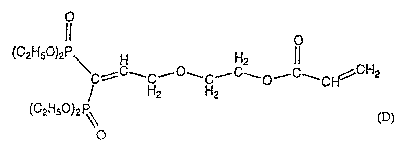
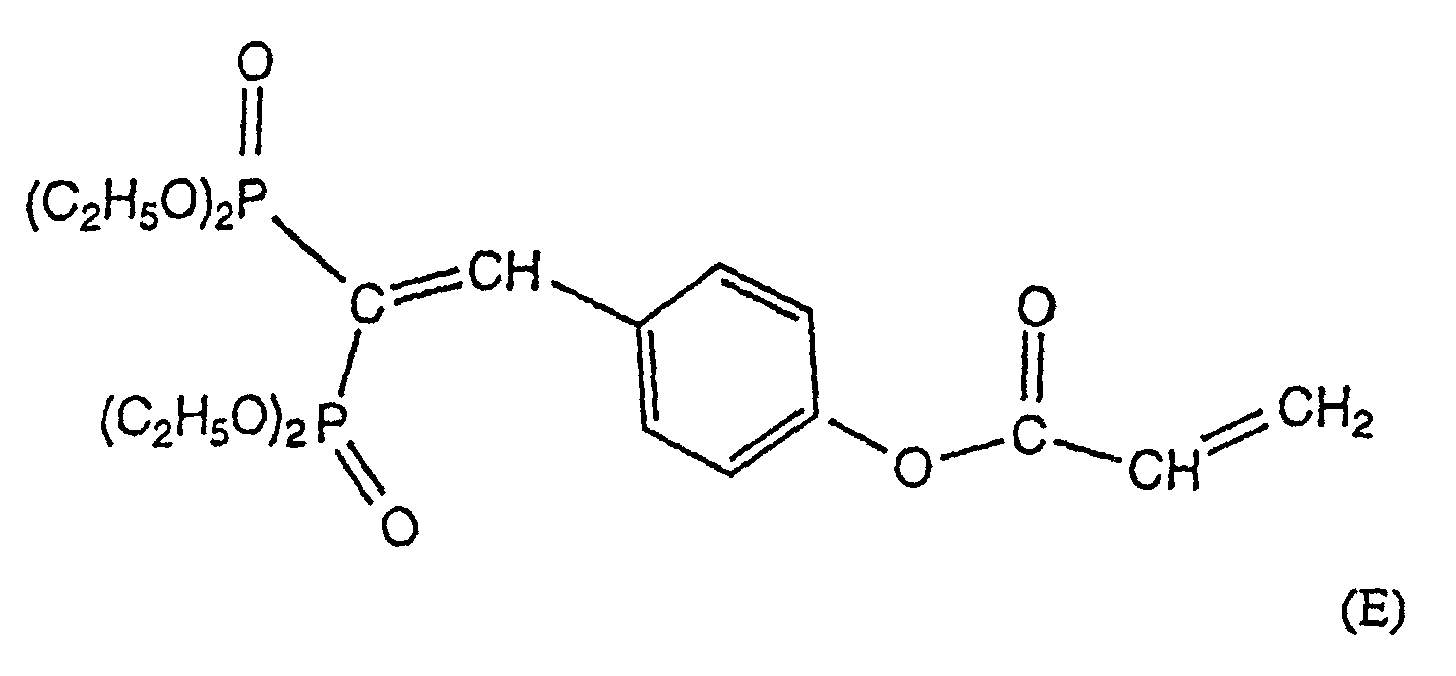
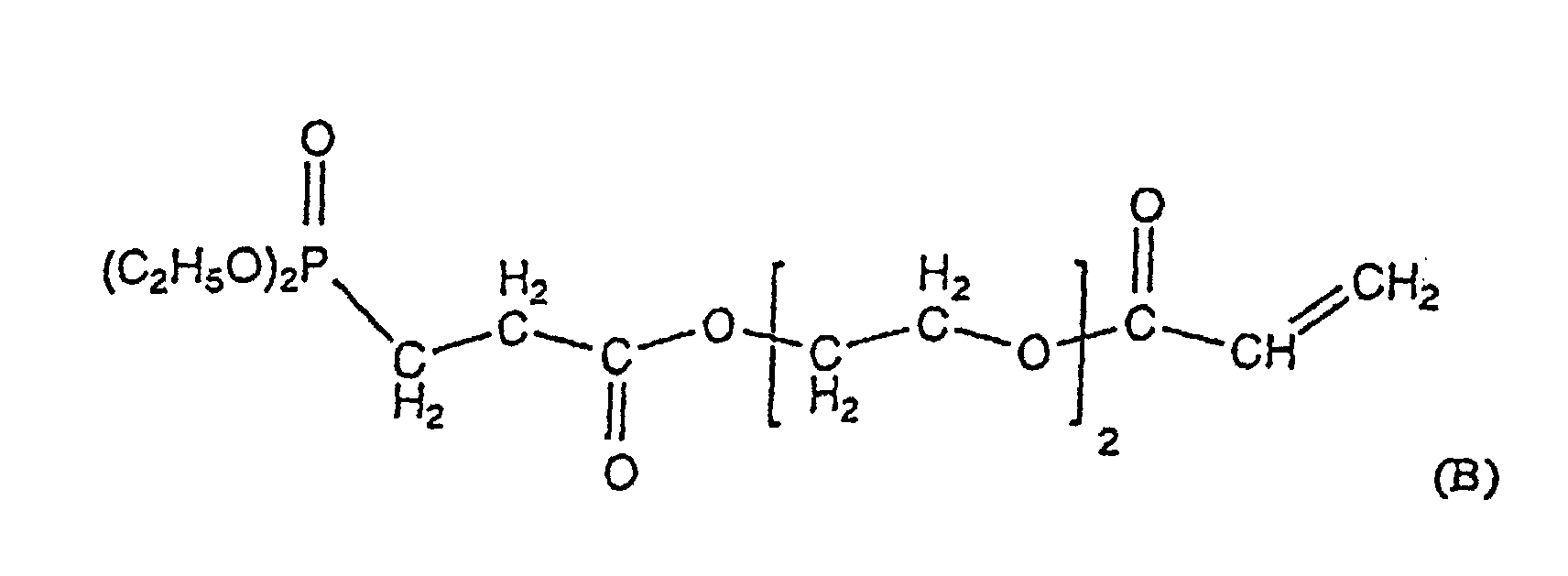
- said compound is chosen from the group consisting of compounds of formulas:
- acrylate thinner for make the liquid reactant mentioned above, it will advantageously be chosen from the group consisting of phenoxyethyl etheracrylate, ethoxyethylacrylate, ethoxyethoxyethylacrylate, trimethylolpropanetriacrylate, isobornylacrylate.
- said liquid agent used is a light-curing liquid reactant comprising at least one compound photoinitiator. Note that we can also consider using reactants which can polymerize under the action of a factor other than light.
- the method according to the invention also comprises a step additional consisting of forming on said wire element coated with said layer thin at least one layer of classic or quasi-classic protective coating with a thickness of less than 60 ⁇ m, preferably less than 40 ⁇ m. Fibers coated according to the process recommended by the invention will therefore then have a diameter smaller than the diameters obtained according to the techniques of the state of the art and will increase the compactness of the corresponding cables.
- the invention also relates to the use of a device for the method described above, this device being characterized in that it comprises means for spraying at least one liquid agent on a wire element.
- the means of spray are integrated into a spray chamber defining a spray enclosure provided with an inlet and an outlet, and the interior of which essentially scrolls said wire element.
- a such an enclosure makes it possible to define a defined volume of spraying and to avoid projections of liquid agent during the operation.
- said orifice inlet of the spray chamber may have a conical shape facilitating the introduction of the wire element of the chamber.
- the spraying means include at least two spray nozzles for distributing said liquid agent according to a cone of spray.
- three nozzles are used. spray evenly distributed around said wire element and these nozzles have a outlet port with a diameter between a few tens to a few hundred microns.
- Such means allow a conical distribution of the jet, the cones formed being inclined at an angle (which can be symbolized by the angle formed by the longitudinal axes of the nozzles and the traveling fiber) preferably between 20 ° and 90 °.
- said spray chamber is provided with an agent recovery gutter liquid sprayed in excess
- said spraying means include at least one reservoir of said liquid agent and the device comprises means for re-routing of the liquid agent recovered in said gutter to said reservoir. It is thus possible to work in a closed circuit to avoid any loss of the agent sprayed liquid.
- the present invention also relates to any optical fiber characterized in that it consists of silica coated with at least one thin layer made from of a liquid reactant and obtained by the process described above.
- said thin layer is deposited directly on the silica.
- said thin layer has a thickness of between a few hundred nanometers and a few micrometers.
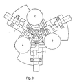
- the spray device for element wired used according to the invention has three spray guns 1 each having a reservoir 2 of liquid agent (in FIGS. 1 and 2, a single gun 1 and its tank 2 are shown). Note that in other embodiments, we may also use a reservoir common to all pistols.
- these pistols are provided with their end of a spray nozzle la.
- the nozzles will have preferably a diameter of a few tens to a few hundred microns.
- the nozzles 1a are positioned in offset planes.
- the product is sprayed in the form of very fine droplets whose advantage is better spreading over the fiber.
- the projected jet is conical which allows to overcome possible displacements of the fiber which can occur during fiberizing. In the mode embodiment shown, the conical jet forms an angle ⁇ of a few degrees.
- the nozzles 1a are inserted into a defined spray chamber 3 by an enclosure 9, a plug 4 positioned above said enclosure 9 and a plug 5 positioned below said enclosure 9.
- the enclosure 9 has orifices 9a for positioning the nozzles la sealed with seals 1b.
- the plug 4 is pierced with a channel 4b allowing the passage of the wire element and provided at its upper end by an orifice conical inlet 4a thereof.
- the diameter of this inlet port can vary from a few hundred microns to a few millimeters.
- the plug 5 is provided with an outlet orifice 5a and a gutter 6 allowing to recover the surplus of product projected against the walls of the enclosure 9 by the guns 1.
- the gutter is connected to an evacuation circuit 7 connected to a return system (not shown) of the product to the tanks 2.
- the pressure is then modified as a function of the fiber drawing speed.
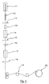
- the device shown in Figures 1 to 3 can easily be integrated into a fiber optic fiber towers, as shown in Figure 4, for spraying of a light-curing liquid reactant in the form of a fine layer with a thickness between a few hundred nanometers and a few micrometers.
- the first deposition device is constituted by a spraying device 10 as described with reference to the figures 1 and 2 and allows the deposition of a liquid reactant on the fiber in the form of a thin layer having a thickness which can vary from a few hundred nanometers to a few micrometers. Note that in other modes of embodiment, it is also possible to integrate several successive spraying systems.
- the pressurized die 16 makes it possible to form on the fiber a additional coating with a thickness of less than 60 ⁇ m, preferably less than 40 ⁇ m Note on this subject that we can use on the fiberizing tower a second pressurized die for depositing a third layer of coating. Note also that we can also spray, deposit the protective coating and polymerize both layers simultaneously.
- the spraying device described with reference to FIGS. 1 and 2 has been used to spray on silica optical fibers a thin layer of various light-curing liquid reagents.
- the composition of these liquid reactants is given in Examples 1 and 2 below.
- the amount of compound A incorporated in this mixture was 20% in weight.
- the liquid obtained had a viscosity of the order of 10 mPa.s, and became shown to be homogeneous and stable over time (no demixing after several months).
- a conventional photoinitiator for UV polymerization has been added to this liquid, in conventional weight proportions.
- the compound of formula E mentioned above was mixed with the solution phenoxyethyletheracrylate / isobornylacrylate mentioned in Example 1 according to the same proportion as in this example.
- the resin obtained was also shown liquid, homogeneous and stable with a viscosity of the order of 10 mPa.s. We have him added a photoinitiator compound for UV polymerization.
- the liquid reactants were also sprayed onto silica plates and the results obtained were compared with the results obtained by plate deposition of silica from conventional coating resins (950-106 and 950-108 from DSM) and solution essentially composed of the phenoxyethyl etheracrylate / isobornylacrylate mixture / photoinitiator.
- UV reactivity has been studied using a photocalorimeter (DPA Perkin Elmer) which provides an exothermic peak during the polymerization of the resin and allows the measurement of the start and end times of reaction from the peak obtained.
- DPA Perkin Elmer a photocalorimeter
- the coating formed being very thin, it was mechanically protected by a coating resin of quasi-classical invoice.
- Such parameters made it possible to obtain a uniform deposit of thickness close to a micron. This thickness was measured by electron microscopy and AFM on film samples without a protective coating.
Landscapes
- Life Sciences & Earth Sciences (AREA)
- Physics & Mathematics (AREA)
- Chemical & Material Sciences (AREA)
- Engineering & Computer Science (AREA)
- Organic Chemistry (AREA)
- Optics & Photonics (AREA)
- Geochemistry & Mineralogy (AREA)
- Materials Engineering (AREA)
- Chemical Kinetics & Catalysis (AREA)
- General Life Sciences & Earth Sciences (AREA)
- General Physics & Mathematics (AREA)
- General Chemical & Material Sciences (AREA)
- Wood Science & Technology (AREA)
- Application Of Or Painting With Fluid Materials (AREA)
- Surface Treatment Of Glass Fibres Or Filaments (AREA)
- Optical Fibers, Optical Fiber Cores, And Optical Fiber Bundles (AREA)
- Nozzles (AREA)
- Details Or Accessories Of Spraying Plant Or Apparatus (AREA)
Abstract
Description
- l'utilisation d'un revêtement primaire contenant un promoteur d'adhésion qui améliore la tenue de la fibre à l'eau et à l'humidité. Ce revêtement primaire est revêtu d'un revêtement secondaire classique et permettrait l'obtention d'un facteur "n" de 30 ;
- l'utilisation d'un revêtement secondaire fluoré dans lequel le greffage d'atomes de fluor, élément hydrophobe, sur les oligomères uréthane-acrylate présents dans la résine de base permet d'améliorer la tenue à l'eau et à l'humidité de la fibre. Le facteur "n" obtenu grâce à un tel procédé est de l'ordre de 40.
- des céramiques tels que les carbures et nitrures de silicium, les carbures de titane ;
- certains métaux tels que l'aluminium, le zinc, le cuivre...;
- le carbone.
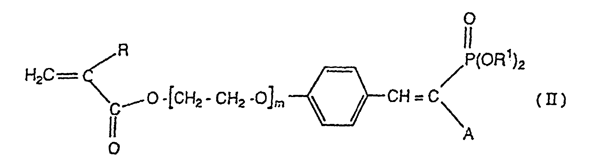
- au moins un composé acrylophosphoré ou méthacrylophosphoré de formule
générale (I) ou de formule générale (II):
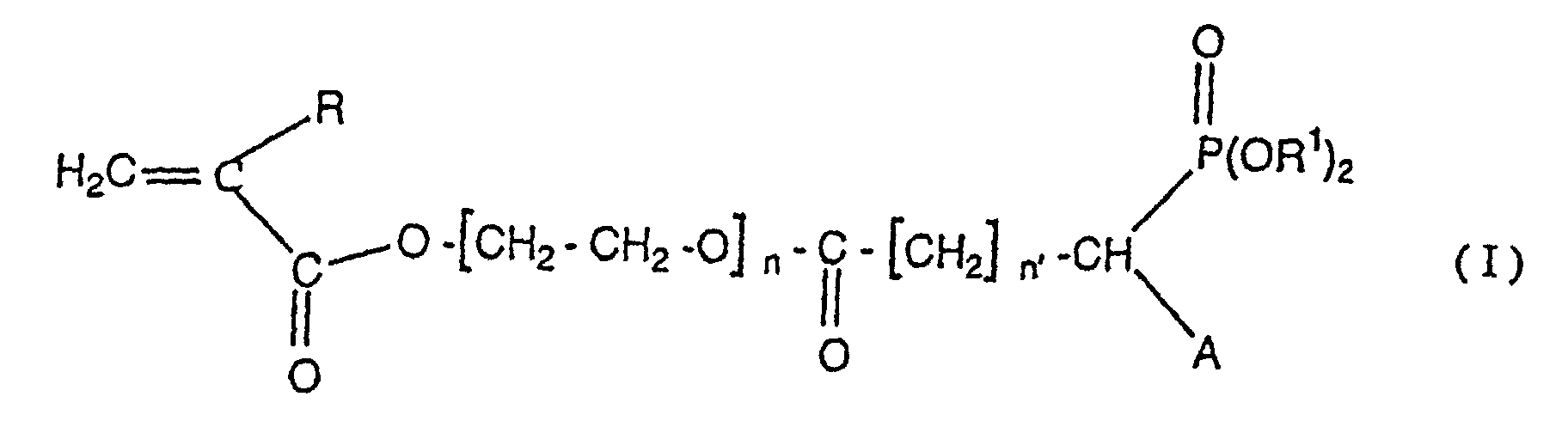 dans lesquelles,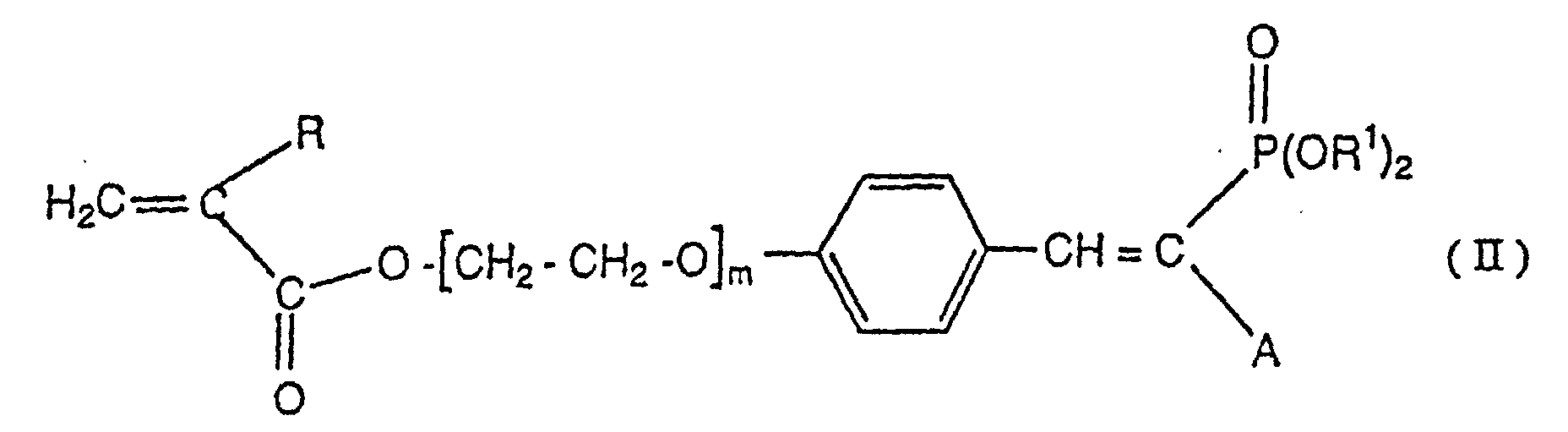
- R représente un atome d'hydrogène ou un reste alkyle, linéaire ou ramifié, ayant un nombre d'atomes de carbone allant de 1 à 3, et de préférence soit un atome d'hydrogène soit un radical méthyle ;
- R1 représente un reste alkyle, linéaire ou ramifié ayant un nombre d'atomes de carbone allant de 1 à 4 et de préférence un radical CH3- ou un radical CH3CH2- ;
- A représente un atome d'hydrogène ou un reste alkyle, linéaire ou ramifié ayant un nombre d'atomes de carbone allant de 1 à 3 ou un autre groupement phosphonate - P(O)(OR1)2 et représente de préférence -P(O)(OCH3)3 ou -P(O)(OEt)2;
- n et n' sont des nombres qui peuvent prendre des valeurs identiques ou différentes égales à 1, 2 ou 3 ;
- m peut être égal à 0, 1, 2 ou 3.
- au moins un diluant acrylate.




- une couche intermédiaire entre deux couches de revêtement classique ou quasi-classique, ou
- une couche de protection extérieure prévue sur une couche de revêtement classique ou quasi-classique.
- la figure 1 représente une vue de face d'un dispositif de pulvérisation d'un agent liquide sur un élément filaire selon l'invention ne montrant, pour les besoins de clarté de la description, qu'un seul pistolet de pulvérisation ;
- la figure 2 représente une vue de face en coupe partielle du dispositif montré à la figure 1 ;
- la figure 3 représente une vue de dessus du dispositif de pulvérisation sur laquelle les trois pistolets de pulvérisation sont montrés ;
- la figure 4 représente une vue schématique d'une tour de fibrage pour fibres optiques intégrant un dispositif de pulvérisation tel que représenté aux figures 1 à 3.
- de protéger l'environnement de l'agent liquide pulvérisé autour de l'élément filaire ;
- de récupérer l'excédent de produit projeté autour de l'élément filaire, grâce à la gouttière 6.
- la pression minimum d'agent liquide pour laquelle le jet conique est uniforme et correctement formé ;
- la pression maximum d'agent liquide pour laquelle la fibre se met à vibrer sous l'effet de l'air sortant des buses.
- un four 11 dans lequel la préforme est ramollie ;
- un système de refroidissement 12 de la fibre de silice sortant du four 11 ;
- un premier dispositif mesureur de diamètre 13 permettant de mesurer le diamètre de la fibre avant revêtement ;
- un premier dispositif de dépôt d'une première couche de revêtement sur la fibre ;
- un four UV 14 permettant de polymériser et ainsi de durcir la couche de revêtement déposée sur la fibre grâce au premier dispositif de dépôt ;
- un second dispositif mesureur de diamètre 15 permettant de mesurer le diamètre de la fibre revêtue de la première couche de revêtement ;
- une filière pressurisée 16 de dépôt d'une seconde couche de revêtement sur la fibre ;
- un second four UV 17 permettant de polymériser et ainsi de durcir la deuxième couche de revêtement déposée sur la fibre grâce à la filière pressurisée 16;
- un troisième dispositif mesureur de diamètre 18 permettant de mesurer le diamètre de la fibre revêtue de la première couche de revêtement et de la seconde couche de revêtement ;
- un assemblage 19 permettant de réceptionner la fibre défilant par gravité dans les éléments cités ci-dessus et incluant une bobine 20.
- on dépose une fine couche de résine (env. 10 µm) sur une plaque de silice au moyen d'un rouleau calibré ;
- on effectue un quadrillage sur la résine polymérisée avec un peigne normalisé; et,
- on évalue l'adhésion selon les décollements observés après passage d'un ruban adhésif normalisé sur la partie quadrillée.
- soit d'augmenter les vitesses de fibrage sans rajouter de fours UV;
- soit de réduire, pour une vitesse donnée, le nombre de fours nécessaires, ce qui apporte un gain sur le coût de fabrication.
- température de transition vitreuse : 40 °C
- module d'Young : de 10 à 1000 MPa
- viscosité : 5000 mPa.s à 25 °C.
- diamètre des buses : quelques centaines de microns ;
- débit de produit pulvérisé : de l'ordre du cm3/min ;
- distance centre des buses-fibres : quelques millimètres.
- une force à la rupture équivalente ;
- un facteur "n" initial sensiblement supérieur et non dégradé après un vieillissement accéléré de 30 jours à 85 °C et 85 % d'humidité relative (mesures réalisées après repos de 24 h à 23 °C et 50 % d'humidité relative).
Claims (23)
- Procédé de dépôt d'au moins une couche mince d'un agent liquide sur un élément filaire destinée à former un revêtement sur ledit élément filaire caractérisé en ce qu'il consiste à pulvériser ledit agent liquide sur ledit élément filaire grâce à des moyens de pulvérisation, ledit élément filaire et lesdits moyens de pulvérisation étant en déplacement relatif l'un par rapport à l'autre, et en ce que ledit agent liquide est un réactant liquide polymérisable comprenant :au moins un composé acrylophosphoré ou méthacrylophosphoré de formule (I) ou de formule (II):
 dans lesquelles,
 R représente un atome d'hydrogène ou un reste alkyle, linéaire ou ramifié, ayant un nombre d'atomes de carbone allant de 1 à 3, et de préférence soit un atome d'hydrogène soit un radical méthyle ;R1 représente un reste alkyle, linéaire ou ramifié ayant un nombre d'atomes de carbone allant de 1 à 4 et de préférence un radical CH3- ou un radical CH3CH2- ;A représente un atome d'hydrogène ou un reste alkyle, linéaire ou ramifié ayant un nombre d'atomes de carbone allant de 1 à 3 ou un autre groupement phosphonate - P(O)(OR1)2 et représente de préférence -P(O)(OCH3)3 ou -P(O)(OEt)2;n et n' sont des nombres qui peuvent prendre des valeurs identiques ou différentes égales à 1, 2 ou 3 ;m peut être égal à 0, 1, 2 ou 3.au moins un diluant acrylate.
 - Procédé selon la revendication I caractérisé en ce que ledit agent liquide présente une viscosité inférieure à 100 mPa.s.
- Procédé selon la revendication 1 ou 2 caractérisé en ce que la pulvérisation dudit agent liquide sur ledit élément filaire est effectuée sous forme d'un jet essentiellement conique.
- Procédé selon la revendication 3 caractérisé en ce que ledit jet essentiellement conique forme un angle α compris entre 1° et 10 °.
- Procédé selon l'une quelconque des revendications 1 à 4 caractérisé en ce que ladite pulvérisation dudit agent liquide est effectuée à une distance comprise entre 1 mm et 20 mm dudit élément filaire.
- Procédé selon l'une quelconque des revendications 1 à 5 caractérisé en ce que ladite étape de pulvérisation est effectuée en utilisant une pression dudit agent liquide comprise entre 0,1 et 2 bars.
- Procédé selon l'une quelconque des revendications 4 à 6 caractérisé en ce qu'il comprend une étape consistant à déterminer une pression minimum de pulvérisation dudit agent liquide pour laquelle ledit jet conique de pulvérisation est correctement formé, une étape consistant à déterminer une pression maximum de pulvérisation dudit agent liquide pour laquelle ledit élément filaire se met à vibrer sous l'effet de la pulvérisation et une étape consistant à fixer une pression optimale de pulvérisation comprise entre ladite pression minimum et ladite pression maximum choisie en fonction de la vitesse de défilement dudit élément filaire.
- Procédé selon l'une quelconque des revendications 1 à 7 caractérisé en ce que ledit composé est choisi dans le groupe constitué par les composés de formule :


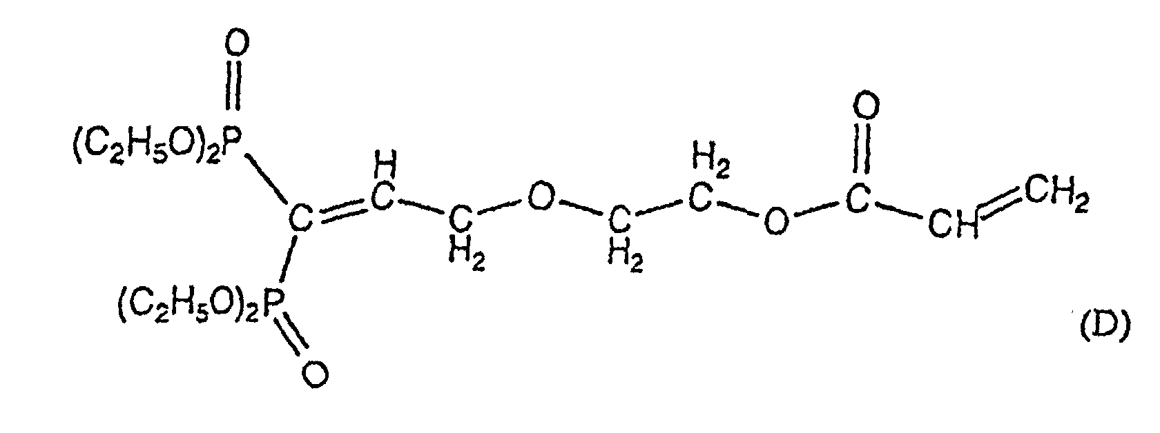

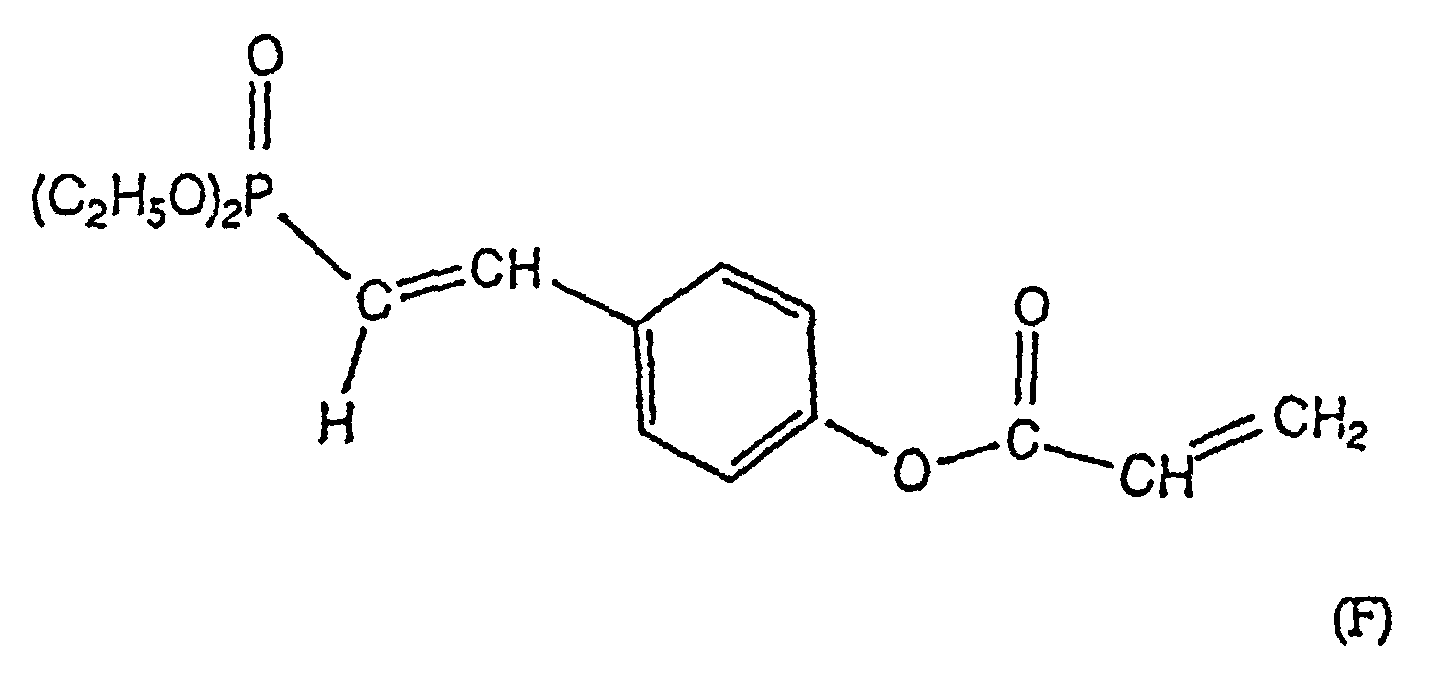
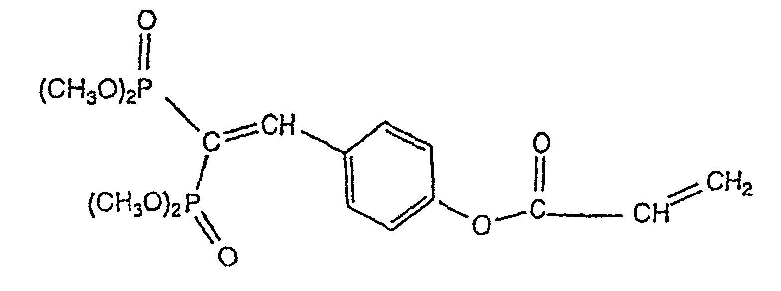
- Procédé selon l'une des revendications 1 à 8 caractérisé en ce que ledit réactant liquide est pulvérisé sur ledit élément filaire pour former une couche d'épaisseur comprise entre quelques centaines de nanomètres et quelques micromètres.
- Procédé selon l'une quelconque des revendications 1 à 9 caractérisé en ce que ledit diluant acrylate est choisi dans le groupe constitué par la phénoxyéthylétheracrylate, l'éthoxyéthylacrylate, l'éthoxyéthoxyéthylacrylate, la triméthylolpropanetriacrylate, l'isobornylacrylate.
- Procédé selon l'une des revendications 1 à 10 caractérisé en ce que ledit réactant liquide photopolymérisable comprend de plus au moins un composé photoinitiateur.
- Procédé selon l'une des revendications 1 à 11 caractérisé en ce qu'il comprend une étape supplémentaire consistant à former sur ledit élément filaire au moins une couche de revêtement secondaire classique ou quasi-classique d'une épaisseur inférieure à 60 µm, préférentiellement inférieure à 40 µm.
- Procédé selon l'une des revendications 1 à 12 caractérisé en ce que ledit élément filaire défile verticalement.
- Utilisation d'un dispositif comprenant des moyens de pulvérisation (1, 2) d'au moins un agent liquide sur un élément filaire ledit agent liquide comprenant au moins un composé acylosphophoré ou métacrylophosphoré, lesdits moyens de pulvérisation (1) comprenant au moins trois buses de pulvérisation équiréparties autour dudit élément filaire et permettant de distribuer ledit agent liquide selon un cône de pulvérisation, pour la mise en oeuvre du procédé selon l'une des revendications 1 à 13
- Utilisation selon la revendication 14 caractérisée en ce que lesdits moyens de pulvérisation (1, 2) sont intégrés dans une chambre de pulvérisation (3) pourvue d'un orifice d'entrée (4a) et d'un orifice de sortie (5a) et à l'intérieur de laquelle défile verticalement ledit élément filaire.
- Utilisation selon l'une des revendications 14 ou 15 caractérisée en ce que lesdits buses (1a) présentent un orifice de sortie d'un diamètre compris entre quelques dizaines à quelques centaines de microns.
- Utilisation selon l'une quelconque des revendications 15 à 16 caractérisée en ce que ladite chambre de pulvérisation (3) est pourvue d'une gouttière (6) de récupération de l'agent liquide pulvérisé en excès.
- Utilisation selon la revendication 17 caractérisée en ce que lesdits moyens de pulvérisation (1) incluent au moins un réservoir (2) dudit agent liquide et en ce qu'il comprend des moyens de réacheminement de l'agent liquide récupéré dans ladite gouttière (6) vers ledit réservoir (2).
- Utilisation d'une tour de fibrage pour fibres optiques comprenant au moins un dispositif (10) de dépôt d'un agent liquide par pulvérisation pour la mise en oeuvre d'un procédé selon l'une des revendications 11 à 13.
- Fibre optique caractérisée en ce qu'elle est constituée d'un coeur de silice revêtue d'au moins une fine couche réalisée à partir d'un réactant liquide d'une épaisseur comprise entre quelques centaines de nanomètres et quelques micromètres obtenue par le procédé selon l'une des revendications 1 à 13.
- Fibre optique selon la revendication 20 caractérisée en ce que ladite fine couche est déposée directement sur la silice.
- Fibre optique selon l'une des revendications 20 ou 21 caractérisée en ce qu'elle comprend en outre au moins une couche de revêtement classique ou quasi-classique et en ce que ladite fine couche forme :une couche intermédiaire entre deux couches de revêtement classique, ouune couche de protection extérieure prévue sur une couche de revêtement classique ou quasi-classique.
- Fibre optique selon l'une des revendications 20 à 22 caractérisée en ce que ladite fine couche présente une épaisseur comprise entre quelques centaines de nanomètres et quelques micromètres.
Applications Claiming Priority (3)
| Application Number | Priority Date | Filing Date | Title |
|---|---|---|---|
| FR9711037 | 1997-09-01 | ||
| FR9711037A FR2767724B1 (fr) | 1997-09-01 | 1997-09-01 | Procede et dispositif pour le revetement d'un element filaire par une couche fine d'agent liquide et fibre optique ainsi revetue |
| PCT/FR1998/001865 WO1999011391A1 (fr) | 1997-09-01 | 1998-08-28 | Procede et dispositif pour le revetement d'un element filaire par une couche fine d'agent liquide et fibre optique ainsi revetue |
Publications (2)
| Publication Number | Publication Date |
|---|---|
| EP1017509A1 EP1017509A1 (fr) | 2000-07-12 |
| EP1017509B1 true EP1017509B1 (fr) | 2003-07-16 |
Family
ID=9510781
Family Applications (1)
| Application Number | Title | Priority Date | Filing Date |
|---|---|---|---|
| EP98942797A Expired - Lifetime EP1017509B1 (fr) | 1997-09-01 | 1998-08-28 | Procede et utilisation d'un dispositif pour le revetement d'un element filaire par une couche fine d'agent liquide et fibre optique ainsi revetue |
Country Status (7)
| Country | Link |
|---|---|
| US (1) | US6258404B1 (fr) |
| EP (1) | EP1017509B1 (fr) |
| JP (1) | JP4323090B2 (fr) |
| CN (1) | CN1137006C (fr) |
| DE (1) | DE69816457T2 (fr) |
| FR (1) | FR2767724B1 (fr) |
| WO (1) | WO1999011391A1 (fr) |
Families Citing this family (8)
| Publication number | Priority date | Publication date | Assignee | Title |
|---|---|---|---|---|
| NL1018338C2 (nl) | 2001-06-20 | 2002-12-30 | Draka Fibre Technology Bv | Optische vezel. |
| US6865322B2 (en) * | 2002-06-04 | 2005-03-08 | Goi Acquisitions Llc | Fiber optic device with enhanced resistance to environmental conditions and method |
| US6741774B2 (en) * | 2002-06-04 | 2004-05-25 | Gould Fiber Optics, Inc. | Fiber optic device with enhanced resistance to environmental conditions and method |
| FI116432B (fi) * | 2003-05-15 | 2005-11-15 | Elektrobit Testing Oy | Menetelmä ja järjestely kanavasimulaation suorittamiseksi |
| US7218820B2 (en) * | 2004-07-22 | 2007-05-15 | Welldynamics, Inc. | Method and system for providing a hydrogen diffusion barrier for fiber optic cables used in hostile environments |
| US6907170B1 (en) | 2004-07-22 | 2005-06-14 | Halliburton Energy Services, Inc. | Hydrogen diffusion delay barrier for fiber optic cables used in hostile environments |
| US7400803B2 (en) * | 2005-03-25 | 2008-07-15 | Welldynamics, B.V. | Method and apparatus for providing a hydrogen diffusion barrier for fiber optic cables used in hostile environments |
| CN100504479C (zh) * | 2004-12-06 | 2009-06-24 | 皮雷利&C.有限公司 | 点对点光纤链路 |
Family Cites Families (5)
| Publication number | Priority date | Publication date | Assignee | Title |
|---|---|---|---|---|
| DE3380845D1 (en) * | 1982-09-03 | 1989-12-21 | Sumitomo Electric Industries | Apparatus for coating optical transmission glass fibers |
| US4606870A (en) * | 1984-07-25 | 1986-08-19 | Essex Group, Inc. | Preparing magnet wire having electron beam curable wire enamels |
| JPH04139038A (ja) * | 1990-09-28 | 1992-05-13 | Sumitomo Electric Ind Ltd | 光ファイバの製造方法及び製造装置 |
| WO1995002004A1 (fr) * | 1993-07-08 | 1995-01-19 | Dsm N.V. | Compositions ignifuges durcissables par irradiation et exemptes d'halogene |
| CN1104230C (zh) * | 1996-12-19 | 2003-04-02 | 花王株式会社 | 牙用涂料组合物 |
-
1997
- 1997-09-01 FR FR9711037A patent/FR2767724B1/fr not_active Expired - Fee Related
-
1998
- 1998-08-28 DE DE69816457T patent/DE69816457T2/de not_active Expired - Lifetime
- 1998-08-28 US US09/485,133 patent/US6258404B1/en not_active Expired - Fee Related
- 1998-08-28 CN CNB988087103A patent/CN1137006C/zh not_active Expired - Fee Related
- 1998-08-28 WO PCT/FR1998/001865 patent/WO1999011391A1/fr not_active Ceased
- 1998-08-28 JP JP2000508480A patent/JP4323090B2/ja not_active Expired - Fee Related
- 1998-08-28 EP EP98942797A patent/EP1017509B1/fr not_active Expired - Lifetime
Also Published As
| Publication number | Publication date |
|---|---|
| FR2767724A1 (fr) | 1999-03-05 |
| FR2767724B1 (fr) | 2001-06-01 |
| DE69816457T2 (de) | 2004-04-15 |
| EP1017509A1 (fr) | 2000-07-12 |
| CN1137006C (zh) | 2004-02-04 |
| DE69816457D1 (de) | 2003-08-21 |
| JP4323090B2 (ja) | 2009-09-02 |
| WO1999011391A1 (fr) | 1999-03-11 |
| CN1268908A (zh) | 2000-10-04 |
| US6258404B1 (en) | 2001-07-10 |
| JP2001514074A (ja) | 2001-09-11 |
Similar Documents
| Publication | Publication Date | Title |
|---|---|---|
| US7466892B2 (en) | Optical and optoelectronic articles | |
| US6696157B1 (en) | Diamond-like glass thin films | |
| FR2522342A1 (fr) | Procede de formation d'un revetement de metal sur une fibre et fibre correspondante | |
| US20180171469A1 (en) | Transparent omniphobic thin film articles | |
| EP2021836B1 (fr) | Article d'optique comportant un revetement externe hydrophobe et/ou oleophobe revetu d'une couche temporaire | |
| WO2007003720A1 (fr) | Revetement de surface hydrophobe et a faible hysteresis de mouillage, procede de depot d'un tel revetement, micro-composant et utilisation | |
| CN1136352A (zh) | 宽频带光纤、光纤芯线、光线缆芯 | |
| FR2992431A1 (fr) | Fibre optique revetue | |
| EP1017509A1 (fr) | Procede et dispositif pour le revetement d'un element filaire par une couche fine d'agent liquide et fibre optique ainsi revetue | |
| EP1261560B1 (fr) | Pellicules de transmission de radiation sur des articles en verre | |
| CA2093543A1 (fr) | Materiau polymere de type polyurethanne acrylate pour revetement de fibre optique ou pour ruban a fibres optiques | |
| EP0251912B1 (fr) | Procédé d'enduction métallique étanche d'une fibre optique , et dispositif mettant en oeuvre ce procédé | |
| FR2780165A1 (fr) | Fibre optique munie d'un revetement de protection et procede de fabrication de cette fibre | |
| CN101971069A (zh) | 光纤心线 | |
| CA3194075A1 (fr) | Utilisation de fibres composite verre-resine pour le renforcement du beton | |
| CA2174856A1 (fr) | Procede d'elaboration d'un revetement protecteur a base de bore amorphe sur une fibre optique, et fibre optique munie d'un tel revetement | |
| US20130230707A1 (en) | Method of making durable articles | |
| CA2291143A1 (fr) | Couche de carbone mince pour guides d'ondes optiques | |
| US6701054B1 (en) | Thin carbon coating of optical waveguides | |
| FR2809720A1 (fr) | Preformes et fibres optiques revetues d'alumines et/ou de silice | |
| BE1010246A3 (fr) | Connecteur pour liaison optique sur base d'un film polymere autoportant d'indice donne et procede de fabrication d'un tel film. | |
| Hamjah et al. | Aerosol Jet Printing of Polymer Optical Waveguides | |
| WO2020212286A1 (fr) | Procédé de formation d'un film de particules à la surface d'un substrat | |
| CN1910485A (zh) | 带透镜的光纤以及制造带透镜的光纤的方法 | |
| JP2003081661A (ja) | 光ファイバの製造方法及び製造装置 |
Legal Events
| Date | Code | Title | Description |
|---|---|---|---|
| PUAI | Public reference made under article 153(3) epc to a published international application that has entered the european phase |
Free format text: ORIGINAL CODE: 0009012 |
|
| 17P | Request for examination filed |
Effective date: 20000125 |
|
| AK | Designated contracting states |
Kind code of ref document: A1 Designated state(s): DE GB IT |
|
| 17Q | First examination report despatched |
Effective date: 20000828 |
|
| GRAH | Despatch of communication of intention to grant a patent |
Free format text: ORIGINAL CODE: EPIDOS IGRA |
|
| RTI1 | Title (correction) |
Free format text: METHOD AND USE OF A DEVICE FOR COATING A WIREFRAME ELEMENT WITH A FINE LIQUID AGENT DEPOSIT AND COATED OPTICAL FIBRE |
|
| GRAH | Despatch of communication of intention to grant a patent |
Free format text: ORIGINAL CODE: EPIDOS IGRA |
|
| GRAA | (expected) grant |
Free format text: ORIGINAL CODE: 0009210 |
|
| AK | Designated contracting states |
Designated state(s): DE GB IT |
|
| REG | Reference to a national code |
Ref country code: GB Ref legal event code: FG4D Free format text: NOT ENGLISH |
|
| RIC1 | Information provided on ipc code assigned before grant |
Ipc: 7C 03C 25/14 B Ipc: 7C 03C 25/28 A |
|
| REF | Corresponds to: |
Ref document number: 69816457 Country of ref document: DE Date of ref document: 20030821 Kind code of ref document: P |
|
| GBT | Gb: translation of ep patent filed (gb section 77(6)(a)/1977) |
Effective date: 20031015 |
|
| PLBE | No opposition filed within time limit |
Free format text: ORIGINAL CODE: 0009261 |
|
| STAA | Information on the status of an ep patent application or granted ep patent |
Free format text: STATUS: NO OPPOSITION FILED WITHIN TIME LIMIT |
|
| 26N | No opposition filed |
Effective date: 20040419 |
|
| PGFP | Annual fee paid to national office [announced via postgrant information from national office to epo] |
Ref country code: DE Payment date: 20110803 Year of fee payment: 14 Ref country code: GB Payment date: 20110728 Year of fee payment: 14 |
|
| PGFP | Annual fee paid to national office [announced via postgrant information from national office to epo] |
Ref country code: IT Payment date: 20110723 Year of fee payment: 14 |
|
| GBPC | Gb: european patent ceased through non-payment of renewal fee |
Effective date: 20120828 |
|
| PG25 | Lapsed in a contracting state [announced via postgrant information from national office to epo] |
Ref country code: IT Free format text: LAPSE BECAUSE OF NON-PAYMENT OF DUE FEES Effective date: 20120828 |
|
| PG25 | Lapsed in a contracting state [announced via postgrant information from national office to epo] |
Ref country code: DE Free format text: LAPSE BECAUSE OF NON-PAYMENT OF DUE FEES Effective date: 20130301 Ref country code: GB Free format text: LAPSE BECAUSE OF NON-PAYMENT OF DUE FEES Effective date: 20120828 |
|
| REG | Reference to a national code |
Ref country code: DE Ref legal event code: R119 Ref document number: 69816457 Country of ref document: DE Effective date: 20130301 |