EP1017503B1 - Apparatus and method for separating blood samples - Google Patents
Apparatus and method for separating blood samples Download PDFInfo
- Publication number
- EP1017503B1 EP1017503B1 EP97912730A EP97912730A EP1017503B1 EP 1017503 B1 EP1017503 B1 EP 1017503B1 EP 97912730 A EP97912730 A EP 97912730A EP 97912730 A EP97912730 A EP 97912730A EP 1017503 B1 EP1017503 B1 EP 1017503B1
- Authority
- EP
- European Patent Office
- Prior art keywords
- fixture
- specimen
- centrifuge
- sample
- receiver
- Prior art date
- Legal status (The legal status is an assumption and is not a legal conclusion. Google has not performed a legal analysis and makes no representation as to the accuracy of the status listed.)
- Expired - Lifetime
Links
- 238000000034 method Methods 0.000 title claims description 17
- 210000004369 blood Anatomy 0.000 title description 18
- 239000008280 blood Substances 0.000 title description 18
- 238000000926 separation method Methods 0.000 claims description 26
- 210000002966 serum Anatomy 0.000 claims description 22
- 238000007789 sealing Methods 0.000 claims description 11
- 239000007788 liquid Substances 0.000 claims description 6
- 210000003743 erythrocyte Anatomy 0.000 claims description 4
- 210000004027 cell Anatomy 0.000 description 27
- 238000012360 testing method Methods 0.000 description 9
- 239000000463 material Substances 0.000 description 8
- 239000000306 component Substances 0.000 description 3
- 238000012546 transfer Methods 0.000 description 3
- 239000003146 anticoagulant agent Substances 0.000 description 2
- 229940127219 anticoagulant drug Drugs 0.000 description 2
- 230000008901 benefit Effects 0.000 description 2
- 230000036512 infertility Effects 0.000 description 2
- 238000009987 spinning Methods 0.000 description 2
- JJLJMEJHUUYSSY-UHFFFAOYSA-L Copper hydroxide Chemical compound [OH-].[OH-].[Cu+2] JJLJMEJHUUYSSY-UHFFFAOYSA-L 0.000 description 1
- 101000882917 Penaeus paulensis Hemolymph clottable protein Proteins 0.000 description 1
- 208000007536 Thrombosis Diseases 0.000 description 1
- 230000009471 action Effects 0.000 description 1
- 230000004913 activation Effects 0.000 description 1
- 239000000443 aerosol Substances 0.000 description 1
- 238000013459 approach Methods 0.000 description 1
- 230000015572 biosynthetic process Effects 0.000 description 1
- 230000017531 blood circulation Effects 0.000 description 1
- 230000023555 blood coagulation Effects 0.000 description 1
- 239000012503 blood component Substances 0.000 description 1
- 210000001772 blood platelet Anatomy 0.000 description 1
- 239000007795 chemical reaction product Substances 0.000 description 1
- 238000004891 communication Methods 0.000 description 1
- 238000013461 design Methods 0.000 description 1
- 201000010099 disease Diseases 0.000 description 1
- 208000037265 diseases, disorders, signs and symptoms Diseases 0.000 description 1
- 230000000694 effects Effects 0.000 description 1
- 238000005516 engineering process Methods 0.000 description 1
- 239000011521 glass Substances 0.000 description 1
- 230000005484 gravity Effects 0.000 description 1
- 238000003780 insertion Methods 0.000 description 1
- 230000037431 insertion Effects 0.000 description 1
- 238000002372 labelling Methods 0.000 description 1
- 238000007648 laser printing Methods 0.000 description 1
- 230000007246 mechanism Effects 0.000 description 1
- 244000005700 microbiome Species 0.000 description 1
- 238000013508 migration Methods 0.000 description 1
- 230000005012 migration Effects 0.000 description 1
- 230000008569 process Effects 0.000 description 1
- 239000000047 product Substances 0.000 description 1
Images


Classifications
-
- B—PERFORMING OPERATIONS; TRANSPORTING
- B04—CENTRIFUGAL APPARATUS OR MACHINES FOR CARRYING-OUT PHYSICAL OR CHEMICAL PROCESSES
- B04B—CENTRIFUGES
- B04B5/00—Other centrifuges
- B04B5/04—Radial chamber apparatus for separating predominantly liquid mixtures, e.g. butyrometers
- B04B5/0407—Radial chamber apparatus for separating predominantly liquid mixtures, e.g. butyrometers for liquids contained in receptacles
- B04B5/0414—Radial chamber apparatus for separating predominantly liquid mixtures, e.g. butyrometers for liquids contained in receptacles comprising test tubes
-
- G—PHYSICS
- G01—MEASURING; TESTING
- G01N—INVESTIGATING OR ANALYSING MATERIALS BY DETERMINING THEIR CHEMICAL OR PHYSICAL PROPERTIES
- G01N33/00—Investigating or analysing materials by specific methods not covered by groups G01N1/00 - G01N31/00
- G01N33/48—Biological material, e.g. blood, urine; Haemocytometers
- G01N33/483—Physical analysis of biological material
- G01N33/487—Physical analysis of biological material of liquid biological material
- G01N33/49—Blood
- G01N33/491—Blood by separating the blood components
Definitions
- the present invention relates to separation of plasma or serum from the red cells of a blood sample and more particularly to an apparatus and method for rapidly achieving such separation.
- plasma or serum is typically separated from the red blood cells of a blood sample by placing whole liquid or clotted blood respectively, in a tube, placing the tube in a swinging bucket type centrifuge which upon activation rotates rapidly and causes the tube to acquire a horizontal position.
- the red cells being heavier than the plasma or serum migrate to the end of the tube furthest from the center of rotation thus producing separation of the various components of the sample.
- the mechanism is very complex requiring two separately driven rotating shafts, two different hollow needles to affect interconnection of the bottle and the receiver, rectangular shaped or other non-cylindrical specimen bottles to ensure that the bottles do not rotate about their own axes.
- This procedure further requires proper registration of the needle with the sample bottle.
- a readily movable self-sealing stopper in the specimen bottle is employed to assist in the search for the strata of the material desired. This procedure may require opening of the specimen bottle to locate the strata interface thus compromising the sterility of the specimen and possibly endangering the workers.
- Still another object of the present invention is to automatically separate serum or plasma into a different container from red blood cells from which the serum or plasma has been extracted.
- Still another object of the present invention is to provide a quite simple assemblage for application to a centrifuge, the assemblage comprised of two test tubes, with self-sealing stoppers, a two ended hollow needle and a universal fixture to hold the tubes and needles in proper coaxial or side by side registration.
- Yet another object of the present intention is to provide an apparatus for rapidly separating plasma or serum from blood samples by an assembly having a fixed structure of small size employing standard test tubes of the type employed by medical and paramedical personnel to withdraw blood from a patient.
- the present invention provides a centrifuge and plasma or serum separation arrangement comprising:
- the preferred embodiment of the present invention is comprised of a spinning drum, which spins a plurality of pairs of head-to-head tubes held coaxially of one another and located around a vertical axis parallel to and spaced from the longitudinal center line of the tubes.
- Each pair of tubes is arranged head to head in which a primary tube contains blood while a collection tube is under vacuum and is empty. The primary or sample tube is located below the collection tube.
- the red cells migrate a quite short distance to one side of the primary or sample tube.
- the separation time is quite short because of the shorter separating distance compared to the present method in which the cells are driven to the bottom of a tube, or in the Shanley patent to the walls of a 500 ml bottle.
- the use of small vessels such as test tubes has the advantage of more uniform pressure across the tube and thus a calculated maximum force may be employed without fear of damage to the specimens. Large vessels do not permit uniform pressures across the vessels so that lower average forces must be employed to insure that excessive pressure is not developed in the sample. Also in larger vessels separation may not be uniform as a result of nonuniform pressure.
- the two tubes of each pair, the sample and collection tubes, are connected during the interval the drum is rotating by a single two sided hollow needle.
- the needle is introduced into the center of each of the tubes through self-sealing stoppers substantially simultaneously.
- the plasma flows into the collection tube by reason of the partial vacuum in the collection tube and the pressure developed by the centrifuging action in the primary tube.
- the sample tube is usually not completely filled, 80% to 90% being the usual. At 90% with 44% red cells, only about 40% of the tube contains red cells thus providing a reasonable margin of safety. With a 41% red cell sample only 37% of the tube is filled with red cells.
- red cells and other non-serum or plasma materials are not near the center of the sample tube as a result of centrifuging and the two ended needle may be located along the center line of the tubes. Red cells are not available to the needle and therefore will not pass into the empty collecting tube.
- This feature provides a plasma or serum containing tube at the end of centrifuging suitable for use in the analytical determinations without any further serum or plasma transfer steps required. Further it is not necessary to perform any function that can compromise the sterility of the sample.
- the fixture which holds the two tubes facing each other and a hollow needle having two sharp ends in between.
- the tubes must have self-sealing stoppers or caps so that the blood flows only through the needle and does not spin out of the tubes.
- the tubes and needle can be snapped on or off the fixture manually or automatically. Further, the fixture with the tubes can be loaded or unloaded manually or automatically onto the drum. After the separation is completed and while the centrifuge is still spinning the two tubes are forced to slide towards each other so that the needle penetrates both stoppers allowing plasma to flow from the primary to the collection tube.
- the needle is preferably held by a disc that is snugly received by the fixture and may be made integral with the fixture. In all cases the needle should be a disposable item.
- the collection tube can be labeled after it is placed in the fixture by any of several well known technologies such as laser printing directly onto the glass or plastic of the collection tube or on a sticky back label so that the collection tube label matches exactly a bar code or other code on a readable label previously applied to the sample tube.
- This approach assure positive specimen identification and replaces a step currently performed by other less dependable methods in which mislabeling of the collection tube can occur.
- Both tubes can be pre-labeled and the labeling verified upon insertion into the centrifuge by a computer or other suitable means.
- the drum is provided with a plurality of bays, each of which can contain a fixture with tubes.
- the bay is directed inwardly opposite to the direction of rotation so that inertia forces the fixture into its designated position.
- the bays are designed, however, such that it is easy to replace the fixtures with the tubes by an external device that loads and unloads the centrifuge.
- the fixture can accommodate tubes of different sizes and different fixtures may be employed for different size tubes.
- the interface with the centrifuge remains the same.
- the above described assemblage is fully functional. If the sample has been drawn into a tube with an anticoagulant, it remains a liquid and the distribution is as stated above. If the sample is drawn into a tube without an anticoagulant the blood clotting proteins will polymerize about the blood platelets which had previously agglutinated, and after a predetermined time say, for instance, 10 minutes, will form a gelatinous mass or blood clot. This mass is usually formed directly in the sample tube and centrifuged. Since the distribution of red cells and related material in the clot and the serum is essentially the same as that of the red cells and plasma in a liquid sample, the assemblage remains the same. Thus regardless of the nature of the specimen or sample, the simple arrangement described above is completely suitable for the task.
- the entire system is designed around the disposables; two test tubes, a needle and a couple of stoppers.
- the fixture may also be disposable.
- the geometry is slender, easily handled and provides short sample separation times. Further the system is designed for automation particularly since assembly of the tubes, fixture, etc. I is quite simple.
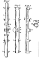
- FIG. 1 illustrates a slot 17 through which the needle passes as the needle holder 12 is inserted into slot 10.
- the needle, needle holder and fixture may be cast as a unit.
- the assemblage is held together by the fixture 6 a slim simple device made of a spring type material so that all elements of the assemblage are firmly held in place.
- the stoppers and the test tubes are normally available in the industry and together with the needle and possibly the fixture are considered disposable.
- the structure is such that the needle may be and preferably is held along the center line of the tubes.
- the bevel of the needle is oriented away from the red cells.
- the fixture's spring fingers at one of its ends may be of a size to accommodate a tube of a different dimension from the fingers at its other end.
- the length of the needle may vary to accommodate tubes of different lengths and may fill the space between the stoppers.
- FIG. 5 there is illustrated a region of the fixture holders 18 of a centrifuge.
- a fixture such as fixture 6 of Figures 1-3, is insertable into each receiver 20 of a centrifuge having a plurality of receivers 20.
- the fixtures are situated with the center line of the tubes and needle parallel to spin center 22 of the centrifuge.
- the spin rate may be anywhere from 60 rps to 120 rps.
- the fixture 6 is of such structure as to interface with the centrifuge regardless of the sizes of the tubes.
- the receivers 20 of the centrifuge may be or are identical and are provided with a notch 21 for receiving a projection 23 on the fixture 6, see Figure 4, to stabilize the position of the structure in the receiver 20.
- Both coagulated and uncoagulated blood may be processed at the same time so as to produce serum in the one instance and plasma in the other.
- the centrifuge as indicated above has numerous pockets and the sample in each pocket has no relationship to the samples in any of the other pockets so that both types of materials can be centrifuged concurrently.
- plasma and/or serum can be the end product or products.
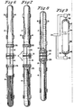
- FIG. 6 tubes 2 and 4 are fully separated (extended) with liquid or coagulated whole blood in sample or lower tube 4.
- Figure 7 illustrates the tubes after centrifuging with the red cells compacted against the region of the tube wall remote from the center of rotation of the centrifuge.
- the red cells constitute only about 37% to a maximum of about 44% in the latter case if the tube is fully filled.
- the center 25 of the lower tube 4 rarely if ever contains red cells as a result of centrifuging for a time necessary to effect complete separation, one minute or less in a standard size tube.
- the tubes 2 and 4 have been pushed together causing needle 14 to penetrate self-sealing stoppers 26 and 28 and establish communication between tubes 2 and 4.
- the vacuum in tube 2 and the pressure created by centrifuging in the sample tube causes the plasma or serum, to be transferred to the upper tube 2.
- the tubes may be separated while the centrifuge is still rotating, the stoppers 26 and 28 sealing their respective tubes.
- the centrifuge may now be stopped, the fixture(s) with tubes may be removed and the tubes processed separately thereafter. If the material remaining in the sample tube is not to be used the sample tube may also be discarded.
- a solenoid 32 is connected to a cap 44 that is disposed about the top of upper tube 34 of an array employed in the present invention.
- a plate 36 presses on the top of the tube 34 to force it down to cause the upper tube 34 to move toward lower tube 38.
- Concurrently solenoid 40 is energized to move lower tube 38 upward whereby the tubes 34 and 38 assume the position of Figure 6 hereof.
- each solenoid shaft On the end of each solenoid shaft is an elastic sleeve with the plate 36 of solenoid 32 at the upper end of the structure as viewed in Figure 9. There is a corresponding plate 42 of solenoid 40 disposed inside of sleeve 46. Upon reversal of polarity to the solenoids, the needle is withdrawn from the tubes.
- the needle be coaxial with the tubes.
- the needle may be off center away from the side of the tubes in which the red cells are collected to further insure in those rare instances that red cells may be near the center so that none of the red cells are drawn into the upper tube. Such an occurrence is quite uncommon if not essentially impossible.
- location of the collection tube above the sample tube permits gravity to assist in the separation of the heavier red cells from the plasma and serum.
- the two tubes be of the same length or diameter.
- a fixture may be provided that can accommodate different size tubes or different fixtures may be provided for each different combination of test tubes or a test tube and plastic tubing. It is not necessary that the upper tube be a test tube.
- hose plastic tubing
- the hose discharges into a suitable container.
- FIG. 10 of the accompanying drawings there is illustrated an arrangement of standard sample and receiver tubes 50 and 52, respectively, arranged side by side.
- the tubes 50 and 52 are held by spring fingers 55 of a fixture 53 that is insertable into pockets of a centrifuge.
- a U-shaped needle 54 is positioned above stoppers 56 and 58 of both tubes and is attached to a leaf spring 51 so as to be poised above the stoppers. Depression of the springs, as by the apparatus of Figure 12, connects the tubes 50 and 52.
- Figure 9 is acceptable for a single pocket arrangement but would be awkward for a multiple pocket arrangement.
- the structure of Figure 12, however, is suitable for multiple pockets.
- a solenoid 80 is symmetrical with respect to axis 82 of the centrifuge 84. Armature 86 of the solenoid 80 provides across its top a plate 88 that lies about all of the pockets of the centrifugre.
- Coil 90 of the solenoid 80 is connected through slip rings 92 located on a surface of the centrifuge.
- the armature 86 and its plate 88 are biased upwardly as viewed in Figure 11 but upon energization of the solenoid the armature is retracted into the coil 90 and the plate presses down on receiver tubes 94 of tube and fixture structures located in the pockets of the centrifuge.
- the sleeve arrangement of Figure 9 may be employed to extract the needle from the tubes.
- the geometry of this system or assemblage is remarkably simple, the fixture 6 is responsible for and does at all times maintain the assemblage.
- the assemblage can handle both coagulated and uncoagulated blood in the centrifuge at the same time.
- the structure is designed around inexpensive disposables. Further because of its slim design it can produce separation of red cells, etc. from serum or plasma in a matter of approximately one minute or less at speeds of 60 to 120 rps.
- the collection tube may be integral with the fixture.
Landscapes
- Health & Medical Sciences (AREA)
- Life Sciences & Earth Sciences (AREA)
- Engineering & Computer Science (AREA)
- Biomedical Technology (AREA)
- Chemical & Material Sciences (AREA)
- Hematology (AREA)
- Physics & Mathematics (AREA)
- Analytical Chemistry (AREA)
- Biochemistry (AREA)
- Urology & Nephrology (AREA)
- Ecology (AREA)
- Food Science & Technology (AREA)
- Medicinal Chemistry (AREA)
- Biophysics (AREA)
- Molecular Biology (AREA)
- General Health & Medical Sciences (AREA)
- General Physics & Mathematics (AREA)
- Immunology (AREA)
- Pathology (AREA)
- Centrifugal Separators (AREA)
- Investigating Or Analysing Biological Materials (AREA)
Description
- The present invention relates to separation of plasma or serum from the red cells of a blood sample and more particularly to an apparatus and method for rapidly achieving such separation.
- In current practice plasma or serum is typically separated from the red blood cells of a blood sample by placing whole liquid or clotted blood respectively, in a tube, placing the tube in a swinging bucket type centrifuge which upon activation rotates rapidly and causes the tube to acquire a horizontal position. The red cells being heavier than the plasma or serum migrate to the end of the tube furthest from the center of rotation thus producing separation of the various components of the sample.
- The above procedure is time consuming requiring extended periods of centrifuging to achieve the desired results because of the long migration path of the red cells.
- U.S. Patent No. 3,190,547 to J.J. Shanley which forms the basis of the pre-characterizing portions of
claims 1 and 10 discloses in Figures 10-13 a centrifuge wherein bottles are located below evacuated plasma receivers. The combination of each bottle and receiver is rotated together with other such combinations about an axis parallel to the axis of each combination, which axis passes through a bottle and receiver. In consequence red cells migrate upon rotation of the bottles about such axis toward the outer walls of the sample bottles. Upon completion of centrifuging the sample bottle and plasma receivers are connected through hollow needles situated in self-sealing stoppers in each member of the combination. The plasma is drawn into the plasma receivers which are then spun at a higher than previous rotational velocity separately from the now stationary specimen bottles to produce further separation of the materials drawn therein. - The mechanism is very complex requiring two separately driven rotating shafts, two different hollow needles to affect interconnection of the bottle and the receiver, rectangular shaped or other non-cylindrical specimen bottles to ensure that the bottles do not rotate about their own axes. This procedure further requires proper registration of the needle with the sample bottle. To provide proper alignment with the various strata in the specimen bottle, a readily movable self-sealing stopper in the specimen bottle is employed to assist in the search for the strata of the material desired. This procedure may require opening of the specimen bottle to locate the strata interface thus compromising the sterility of the specimen and possibly endangering the workers.
- It is an object of the present invention to greatly shorten the time required to separate the components of either anticoagulated and/or clotted blood samples.
- It is another object of the present invention to produce separation of the red blood cells from other components of whole blood in a system in which the plasma or serum at the end of the process is disposed in a separate container from the red cells.
- Still another object of the present invention is to automatically separate serum or plasma into a different container from red blood cells from which the serum or plasma has been extracted.
- Still another object of the present invention is to provide a quite simple assemblage for application to a centrifuge, the assemblage comprised of two test tubes, with self-sealing stoppers, a two ended hollow needle and a universal fixture to hold the tubes and needles in proper coaxial or side by side registration.
- Yet another object of the present intention is to provide an apparatus for rapidly separating plasma or serum from blood samples by an assembly having a fixed structure of small size employing standard test tubes of the type employed by medical and paramedical personnel to withdraw blood from a patient.
- It is another object of the invention to provide a fixture for holding the assemblage in registration, the fixtures all having a universal interface for registration with a centrifuge designed for such purpose and having a second interface that varies only with the dimensions of the test tubes. Thus loading and unloading of the centrifuge is simple and lends itself to automated input to and output from the machine. Also such arrangement increases safety by reducing the contact of laboratory personnel with the equipment and the danger of contact with potentially contaminated blood.
- The present invention provides a centrifuge and plasma or serum separation arrangement comprising:
- (a) a plurality of sample holders (4);
- (b) a plurality of specimen receivers (2, 94);
- (c) a centrifuge having a member (18, 84) rotatable at high speed about an axis;
- (d) self-sealing stoppers (26) for said sample holders and said specimen receivers;
- (e) a plurality of hollow needles (14) for piercing said stoppers (26), each needle of said needles having two sharp ends, and
- (f) means (80, 86, 88, 90, 92) on said centrifuge for causing said needles to pierce said stoppers,
characterized in that the separation arrangement further comprises: - (g) a plurality of unitary fixtures (6), each fixture of said fixtures for holding, in collinear or side by side alignment, a sample holder (4) of said sample holders and a specimen receiver (2, 94) of said specimen receivers.
- The preferred embodiment of the present invention is comprised of a spinning drum, which spins a plurality of pairs of head-to-head tubes held coaxially of one another and located around a vertical axis parallel to and spaced from the longitudinal center line of the tubes. Each pair of tubes is arranged head to head in which a primary tube contains blood while a collection tube is under vacuum and is empty. The primary or sample tube is located below the collection tube.
- When the drum rotates, the red cells migrate a quite short distance to one side of the primary or sample tube. The separation time is quite short because of the shorter separating distance compared to the present method in which the cells are driven to the bottom of a tube, or in the Shanley patent to the walls of a 500 ml bottle. There is less chance of damage to the red cells due to the smaller radial pressure required. The use of small vessels such as test tubes has the advantage of more uniform pressure across the tube and thus a calculated maximum force may be employed without fear of damage to the specimens. Large vessels do not permit uniform pressures across the vessels so that lower average forces must be employed to insure that excessive pressure is not developed in the sample. Also in larger vessels separation may not be uniform as a result of nonuniform pressure.
- The two tubes of each pair, the sample and collection tubes, are connected during the interval the drum is rotating by a single two sided hollow needle. The needle is introduced into the center of each of the tubes through self-sealing stoppers substantially simultaneously. The plasma flows into the collection tube by reason of the partial vacuum in the collection tube and the pressure developed by the centrifuging action in the primary tube. It is to be noted that in humans the red cell and other non-plasma or serum volume of blood represents about 44% in males and 41% in females. The sample tube is usually not completely filled, 80% to 90% being the usual. At 90% with 44% red cells, only about 40% of the tube contains red cells thus providing a reasonable margin of safety. With a 41% red cell sample only 37% of the tube is filled with red cells. Thus the red cells and other non-serum or plasma materials are not near the center of the sample tube as a result of centrifuging and the two ended needle may be located along the center line of the tubes. Red cells are not available to the needle and therefore will not pass into the empty collecting tube. This feature provides a plasma or serum containing tube at the end of centrifuging suitable for use in the analytical determinations without any further serum or plasma transfer steps required. Further it is not necessary to perform any function that can compromise the sterility of the sample.
- Further, in accordance with the preferred embodiment, there is a fixture which holds the two tubes facing each other and a hollow needle having two sharp ends in between. The tubes must have self-sealing stoppers or caps so that the blood flows only through the needle and does not spin out of the tubes. The tubes and needle can be snapped on or off the fixture manually or automatically. Further, the fixture with the tubes can be loaded or unloaded manually or automatically onto the drum. After the separation is completed and while the centrifuge is still spinning the two tubes are forced to slide towards each other so that the needle penetrates both stoppers allowing plasma to flow from the primary to the collection tube. The needle is preferably held by a disc that is snugly received by the fixture and may be made integral with the fixture. In all cases the needle should be a disposable item.
- The collection tube can be labeled after it is placed in the fixture by any of several well known technologies such as laser printing directly onto the glass or plastic of the collection tube or on a sticky back label so that the collection tube label matches exactly a bar code or other code on a readable label previously applied to the sample tube. This approach assure positive specimen identification and replaces a step currently performed by other less dependable methods in which mislabeling of the collection tube can occur. Both tubes can be pre-labeled and the labeling verified upon insertion into the centrifuge by a computer or other suitable means.
- Furthermore, the drum is provided with a plurality of bays, each of which can contain a fixture with tubes. The bay is directed inwardly opposite to the direction of rotation so that inertia forces the fixture into its designated position. The bays are designed, however, such that it is easy to replace the fixtures with the tubes by an external device that loads and unloads the centrifuge. The fixture can accommodate tubes of different sizes and different fixtures may be employed for different size tubes. The interface with the centrifuge remains the same.
- Regardless of the nature of the sample, the above described assemblage is fully functional. If the sample has been drawn into a tube with an anticoagulant, it remains a liquid and the distribution is as stated above. If the sample is drawn into a tube without an anticoagulant the blood clotting proteins will polymerize about the blood platelets which had previously agglutinated, and after a predetermined time say, for instance, 10 minutes, will form a gelatinous mass or blood clot. This mass is usually formed directly in the sample tube and centrifuged. Since the distribution of red cells and related material in the clot and the serum is essentially the same as that of the red cells and plasma in a liquid sample, the assemblage remains the same. Thus regardless of the nature of the specimen or sample, the simple arrangement described above is completely suitable for the task.
- As will become apparent subsequently the entire system is designed around the disposables; two test tubes, a needle and a couple of stoppers. The fixture may also be disposable. The geometry is slender, easily handled and provides short sample separation times. Further the system is designed for automation particularly since assembly of the tubes, fixture, etc. I is quite simple.
- The above and other features, objects and advantages of the present invention, together with the best means contemplated by the inventors for carrying out the invention will become more apparent from reading the following description of a preferred embodiment and perusing the associated drawings in which:
-
- Figure 1 is a front view of the assembled containers, the needle and the fixture for holding the assembled containers;
- Figure 2 is a front view of the fixture;
- Figure 3 is a side view of the fixture;
- Figure 4 is a detail taken along section line 4-4 of Figure 3;
- Figure 5 is a top view of the part of the centrifuge for holding the fixtures, containers and needles;
- Figure 6 illustrates the tubes, fixture and needle with lower tube filled with whole blood;
- Figure 7 illustrates the separation of the blood components as a result of centrifuging;
- Figure 8 illustrates the position of the tubes upon transfer of materials;
- Figure 9 is a view of one of the chambers for holding a fixture, container and needle illustrating the location of the solenoids for bringing the containers together and for separating them;
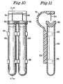
- Figure 10 illustrates a different arrangement of the sample and collection tubes;
- Figure 11 is a side view of the apparatus of Figure 10; and
- Figure 12 illustrates a structure for causing all of the needles of various structures in the pockets of a centrifuge to pierce their associated tube structures concurrently.
- Referring specifically to Figures 1-4 of the accompanying drawings, two
tubes fixture 6. The fixture has several sets ofopposed spring fingers 8 for grasping the tubes when inserted into thefixture 6. Two sets of spring fingers are illustrated for each tube. Located in the center of the fixture is aslot 10 for receiving a slottedneedle holder 12. Aneedle 14 may be integral withfixture 6. The needle holder is insertable intohorizontal slot 10 of Figures 1-3 with the needle seated invertical channels 16, Figure 2. Thus the needle is firmly held in place, Figure 1. The position of theneedle 14 andneedle holder 12 is clearly illustrated in Figure 1. Figure 4 illustrates a slot 17 through which the needle passes as theneedle holder 12 is inserted intoslot 10. The needle, needle holder and fixture may be cast as a unit. - The assemblage is held together by the fixture 6 a slim simple device made of a spring type material so that all elements of the assemblage are firmly held in place. The stoppers and the test tubes are normally available in the industry and together with the needle and possibly the fixture are considered disposable. As previously indicated the structure is such that the needle may be and preferably is held along the center line of the tubes. The bevel of the needle is oriented away from the red cells. The fixture's spring fingers at one of its ends may be of a size to accommodate a tube of a different dimension from the fingers at its other end. Also the length of the needle may vary to accommodate tubes of different lengths and may fill the space between the stoppers.
- Referring to Figure 5, there is illustrated a region of the
fixture holders 18 of a centrifuge. A fixture, such asfixture 6 of Figures 1-3, is insertable into eachreceiver 20 of a centrifuge having a plurality ofreceivers 20. The fixtures are situated with the center line of the tubes and needle parallel to spincenter 22 of the centrifuge. The spin rate may be anywhere from 60 rps to 120 rps. - The
fixture 6 is of such structure as to interface with the centrifuge regardless of the sizes of the tubes. As can be seen in Figure 5 thereceivers 20 of the centrifuge may be or are identical and are provided with anotch 21 for receiving aprojection 23 on thefixture 6, see Figure 4, to stabilize the position of the structure in thereceiver 20. - Both coagulated and uncoagulated blood may be processed at the same time so as to produce serum in the one instance and plasma in the other. The centrifuge as indicated above has numerous pockets and the sample in each pocket has no relationship to the samples in any of the other pockets so that both types of materials can be centrifuged concurrently. Thus plasma and/or serum can be the end product or products.
- Reference is now made to Figures 6-8. In Figure 6
tubes lower tube 4. Figure 7 illustrates the tubes after centrifuging with the red cells compacted against the region of the tube wall remote from the center of rotation of the centrifuge. The red cells constitute only about 37% to a maximum of about 44% in the latter case if the tube is fully filled. Thus thecenter 25 of thelower tube 4 rarely if ever contains red cells as a result of centrifuging for a time necessary to effect complete separation, one minute or less in a standard size tube. - Referring now to Figure 8 of the accompanying drawings, the
tubes needle 14 to penetrate self-sealingstoppers tubes tube 2 and the pressure created by centrifuging in the sample tube causes the plasma or serum, to be transferred to theupper tube 2. Thereafter the tubes may be separated while the centrifuge is still rotating, thestoppers - Referring to Figure 9, a
solenoid 32 is connected to acap 44 that is disposed about the top ofupper tube 34 of an array employed in the present invention. Aplate 36 presses on the top of thetube 34 to force it down to cause theupper tube 34 to move towardlower tube 38. Concurrentlysolenoid 40 is energized to movelower tube 38 upward whereby thetubes - On the end of each solenoid shaft is an elastic sleeve with the
plate 36 ofsolenoid 32 at the upper end of the structure as viewed in Figure 9. There is acorresponding plate 42 ofsolenoid 40 disposed inside ofsleeve 46. Upon reversal of polarity to the solenoids, the needle is withdrawn from the tubes. - It is not necessary that the needle be coaxial with the tubes. The needle may be off center away from the side of the tubes in which the red cells are collected to further insure in those rare instances that red cells may be near the center so that none of the red cells are drawn into the upper tube. Such an occurrence is quite uncommon if not essentially impossible. Note the level of the needle away from the red cells. Further, location of the collection tube above the sample tube permits gravity to assist in the separation of the heavier red cells from the plasma and serum. It is not necessary that the two tubes be of the same length or diameter. A fixture may be provided that can accommodate different size tubes or different fixtures may be provided for each different combination of test tubes or a test tube and plastic tubing. It is not necessary that the upper tube be a test tube. It can be a hose (plastic tubing) connected, for instance, to a vacuum pump that is energized at approximately the same time as the solenoid to produce puncture of the self-sealing stopper by the needle. The hose discharges into a suitable container.
- Referring now to Figure 10 of the accompanying drawings, there is illustrated an arrangement of standard sample and
receiver tubes tubes spring fingers 55 of afixture 53 that is insertable into pockets of a centrifuge. AU-shaped needle 54 is positioned abovestoppers leaf spring 51 so as to be poised above the stoppers. Depression of the springs, as by the apparatus of Figure 12, connects thetubes - It is apparent that at no time in the procedure is the sample, the serum or the plasma exposed to the air and thus its contents cannot reach the external environment. The risk is eliminated to blood workers of exposure to disease causing microorganisms in blood in this step that otherwise could occur upon removal of the stopper from either tube. Removal of a stopper is accompanied by formation of droplets or aerosol from liquid blood or clots during manual transfer of plasma or serum to a secondary collection tube.
- The arrangements of Figure 9 is acceptable for a single pocket arrangement but would be awkward for a multiple pocket arrangement. The structure of Figure 12, however, is suitable for multiple pockets. In this structure a
solenoid 80 is symmetrical with respect toaxis 82 of thecentrifuge 84.Armature 86 of thesolenoid 80 provides across its top aplate 88 that lies about all of the pockets of the centrifugre.Coil 90 of thesolenoid 80 is connected throughslip rings 92 located on a surface of the centrifuge. - The
armature 86 and itsplate 88 are biased upwardly as viewed in Figure 11 but upon energization of the solenoid the armature is retracted into thecoil 90 and the plate presses down onreceiver tubes 94 of tube and fixture structures located in the pockets of the centrifuge. The sleeve arrangement of Figure 9 may be employed to extract the needle from the tubes. - The geometry of this system or assemblage is remarkably simple, the
fixture 6 is responsible for and does at all times maintain the assemblage. The assemblage can handle both coagulated and uncoagulated blood in the centrifuge at the same time. The structure is designed around inexpensive disposables. Further because of its slim design it can produce separation of red cells, etc. from serum or plasma in a matter of approximately one minute or less at speeds of 60 to 120 rps. In still another arrangement the collection tube may be integral with the fixture.
Claims (14)
- A centrifuge and plasma or serum separation arrangement comprising:(a) a plurality of sample holders (4);(b) a plurality of specimen receivers (2, 94);(c) a centrifuge having a member (18, 84) rotatable at high speed about an axis;(d) self-sealing stoppers (26) for said sample holders and said specimen receivers;(e) a plurality of hollow needles (14) for piercing said stoppers (26), each needle of said needles having two sharp ends, and(f) means (80, 86, 88, 90, 92) on said centrifuge for causing said needles to pierce said stoppers,characterized in that the separation arrangement further comprises:(g) a plurality of unitary fixtures (6), each fixture of said fixtures for holding, in collinear or side by side alignment, a sample holder (4) of said sample holders and a specimen receiver (2, 94) of said specimen receivers.
- The separation arrangement of claim 1 wherein said centrifuge member (18, 84) has a plurality of pockets (20) displaced from said axis, each pocket (20) of said pockets for receiving a said fixture (6).
- The separation arrangement of claim 2 wherein an axis of each fixture when received in a said pocket is parallel to said axis of said member (18, 84).
- The separation arrangement of either claim 2 or claim 3 wherein each said fixture (6) has an outwardly extending projection (23), and wherein each said pocket (20) has means (21) to engage said projection so as to maintain an orientation of said fixture in said pocket.
- The separation arrangement of any preceding claim wherein said sample holders (4) and said specimen receivers (2, 94) are of different sizes, and wherein said fixtures (6) are adapted to receive said sample holders and said specimen receivers of said different sizes.
- The separation arrangement of any preceding claim wherein each fixture (6) includes spring fingers (8) for holding said sample holders (4) and said specimen receivers (2, 94).
- The separation arrangement of claim 6 wherein each fixture (6) includes a long narrow spine, said spring fingers (8) being spaced along a length of said spine and extending from said spine, said fingers (8) having a shape to engage and hold cylindrical objects, wherein each fixture (6) iricludes outwardly extending rigid fingers located between two of said spring fingers (8) and defining a narrow slot (10) perpendicular to said length of said spine, and wherein each fixture includes a disc (12), said slot (10) dimensioned to snugly receive said disc (12), said slot (10) defined by top and bottom members having narrow recesses (17) aligned with said length of said spine.
- The separation arrangement of either claim 6 or claim 7 wherein said spring fingers (8) permit a said sample holder (4) and said receiver (2, 94) held by a said fixture (6) to be moved toward one another such that a said needle (14) held by said fixture (6) pierces said stoppers (26) of said sample holder and said receiver.
- The separation arrangement of any preceding claim wherein said means (80, 86, 88, 90, 92) for causing said needles (14) to pierce said stoppers (26) include means for exerting a force directed along an axis of said fixtures, so as to bring said sample holders (4) and said receivers (2, 94) sufficiently close together to cause said needles to pass through said stoppers and enter said sample holders and said receivers.
- A method of rapidly separating plasma or serum from red blood cells, the method comprising:(a) providing:(i) a plurality of sample holders (4);(ii) a plurality of specimen receivers (2, 94);(iii) a centrifuge having a member (18, 84) rotatable at high speed about an axis,(iv) self-sealing stoppers (26) for said sample holders and said specimen receivers;(v) a plurality of hollow needles (14) for piercing said stoppers (26), each needle of said needles having two sharp ends, and(vi) means (80, 86, 88, 90, 92) on said centrifuge for causing said needles to pierce said stoppers;(b) aligning a sample holder (4) of said sample holders, a specimen receiver (2, 94) of said specimen receivers, and a said needle (14);characterized in that the method further comprises the step of:(c) holding, in collinear or side by side alignment, said sample holder (4) and said specimen receiver (2, 94), using a unitary fixture (6).
- The method of claim 10 wherein said centrifuge member (18, 84) has a plurality of pockets (20) displaced from said axis, each pocket of said pockets for receiving a said fixture (6), the method further comprising the step of:(d) inserting said unitary fixture (6) including said sample holder (4), said specimen receiver (2, 94), and said needle (14), into a said pocket (20).
- The method of claim 11 further comprising the steps of:(e) rotating said holder (4) and said receiver (2, 94) using said centrifuge;(f) after a separation has been effected, causing said holder (4) and said receiver (2, 94) to be moved relative to one another so as to cause said needle (14) to enter said holder (4) and said receiver (2, 94) through said stoppers (26), thereby allowing the flow of separated liquid from the sample holder (4) into the specimen receiver (2, 94), and(g) separating said holder (4) and said receiver (2, 94) while said centrifuge is still rotating, so as to remove said needle (14) from said holders and said receivers.
- The method of claim 12 further comprising the step of maintaining a vacuum in a specimen receiver (2, 94) of said specimen receivers during step (e).
- The method of claim 10 wherein said fixture is configured, at one end, to be received by a pocket of said member, and is adapted to receive any of said plurality of sample holders, said sample holders being of different sizes.
Applications Claiming Priority (5)
| Application Number | Priority Date | Filing Date | Title |
|---|---|---|---|
| US73423596A | 1996-10-21 | 1996-10-21 | |
| US734235 | 1996-10-21 | ||
| US08/897,420 US6132353A (en) | 1996-10-21 | 1997-07-21 | Apparatus and method for separating plasma or serum from the red cells of a blood sample |
| US897420 | 1997-07-21 | ||
| PCT/US1997/018571 WO1998017397A1 (en) | 1996-10-21 | 1997-10-20 | Apparatus and method for separating blood samples |
Publications (3)
| Publication Number | Publication Date |
|---|---|
| EP1017503A1 EP1017503A1 (en) | 2000-07-12 |
| EP1017503A4 EP1017503A4 (en) | 2002-07-31 |
| EP1017503B1 true EP1017503B1 (en) | 2006-07-12 |
Family
ID=27112698
Family Applications (1)
| Application Number | Title | Priority Date | Filing Date |
|---|---|---|---|
| EP97912730A Expired - Lifetime EP1017503B1 (en) | 1996-10-21 | 1997-10-20 | Apparatus and method for separating blood samples |
Country Status (7)
| Country | Link |
|---|---|
| US (2) | US6132353A (en) |
| EP (1) | EP1017503B1 (en) |
| JP (1) | JP2002509480A (en) |
| AU (1) | AU733746B2 (en) |
| CA (1) | CA2248088C (en) |
| DE (1) | DE69736334T2 (en) |
| WO (1) | WO1998017397A1 (en) |
Families Citing this family (21)
| Publication number | Priority date | Publication date | Assignee | Title |
|---|---|---|---|---|
| US7456024B2 (en) | 2001-08-29 | 2008-11-25 | Hexal Pharma Gmbh | Method and device for preparing a sample of biological origin in order to determine at least one constituent contained therein |
| US6905453B2 (en) * | 2003-01-29 | 2005-06-14 | Manfred Grumberg | System and method for centrifugal separating of blood components and for sampling therefrom |
| WO2007002580A2 (en) * | 2005-06-23 | 2007-01-04 | Bioveris Corporation | Diagnostic as say system with multi -well reagent container |
| JP3890066B2 (en) * | 2005-06-27 | 2007-03-07 | 積水化学工業株式会社 | Blood separation instrument and blood separation device |
| KR100767448B1 (en) * | 2006-06-30 | 2007-10-17 | 메디칸(주) | Centrifuge and Centrifugal Method |
| JP2012515931A (en) * | 2008-04-25 | 2012-07-12 | ウィンケルマン、ジェイムズ | System and method for determining total blood count and white blood cell percentage |
| US9602777B2 (en) * | 2008-04-25 | 2017-03-21 | Roche Diagnostics Hematology, Inc. | Systems and methods for analyzing body fluids |
| GB2461076A (en) * | 2008-06-20 | 2009-12-23 | James Love | Devices and methods for the separation of blood serum from a blood sample |
| US8177072B2 (en) | 2008-12-04 | 2012-05-15 | Thermogenesis Corp. | Apparatus and method for separating and isolating components of a biological fluid |
| CN103338800B (en) * | 2010-11-29 | 2015-07-01 | 赛诺菲-安万特德国有限公司 | Dispense interface component for a drug delivery device |
| US9111343B2 (en) | 2011-01-18 | 2015-08-18 | Roche Diagnostics Hematology, Inc. | Microscope slide coordinate system registration |
| JP2013132241A (en) * | 2011-12-26 | 2013-07-08 | Otsuka Pharmaceut Factory Inc | Cell separation device |
| JP5748648B2 (en) * | 2011-12-26 | 2015-07-15 | 国立研究開発法人国立循環器病研究センター | Cell separation device and centrifugation method |
| FR3007671B1 (en) * | 2013-07-01 | 2015-07-17 | Chopin Technologies | SECURING DEVICE. |
| FR3007670B1 (en) * | 2013-07-01 | 2017-01-06 | Chopin Tech | SECURING AND CENTRIFUGING DEVICE. |
| EP3386391B1 (en) | 2015-12-11 | 2020-11-25 | Babson Diagnostics, Inc. | Specimen container and method for separating serum or plasma from whole blood |
| US20190331703A1 (en) | 2016-11-14 | 2019-10-31 | Siemens Healthcare Diagnostics Inc. | Sample preparation device |
| JP6831539B2 (en) * | 2017-05-22 | 2021-02-17 | 栄研化学株式会社 | Reagent cartridge |
| EP3967401B1 (en) * | 2020-09-10 | 2022-12-21 | F. Hoffmann-La Roche AG | Fluid transfer device and method for interconnecting vessels |
| US12050052B1 (en) | 2021-08-06 | 2024-07-30 | Babson Diagnostics, Inc. | Refrigerated carrier device for biological samples |
| WO2023196922A1 (en) | 2022-04-06 | 2023-10-12 | Babson Diagnostics, Inc. | Automated centrifuge loader |
Family Cites Families (22)
| Publication number | Priority date | Publication date | Assignee | Title |
|---|---|---|---|---|
| US1718593A (en) * | 1927-02-15 | 1929-06-25 | Arthur E Smith | Ampul |
| US1928998A (en) * | 1930-02-12 | 1933-10-03 | Kovacs Nikolaus | Double ampule for sterile solutions |
| US3190547A (en) * | 1963-07-29 | 1965-06-22 | Giovanni Raccuglia | Method and apparatus for centrifugally fractionating liquid mixtures |
| US3494508A (en) * | 1968-05-10 | 1970-02-10 | Peter Stauton Hoefer | Fractionator |
| US3586064A (en) * | 1969-09-03 | 1971-06-22 | Metropolitan Pathology Lab Inc | Blood serum collection tube and method of collection |
| US3654925A (en) * | 1969-09-23 | 1972-04-11 | Becton Dickinson Co | Plasma separator system |
| FR2076223A5 (en) * | 1970-01-07 | 1971-10-15 | Commissariat Energie Atomique | |
| US3771965A (en) * | 1971-04-23 | 1973-11-13 | R Grams | Biological fluid sampling apparatus |
| US3872867A (en) * | 1971-06-02 | 1975-03-25 | Upjohn Co | Wet-dry additive assembly |
| US3826260A (en) * | 1971-12-27 | 1974-07-30 | Upjohn Co | Vial and syringe combination |
| US3983037A (en) * | 1973-11-05 | 1976-09-28 | Jae Yoon Lee | Apparatus for transfer, storage, and distribution of liquid |
| US4030663A (en) * | 1974-04-04 | 1977-06-21 | Beckman Instruments, Inc. | Tube adaptor for centrifuge rotor bucket |
| FI51052C (en) * | 1975-02-14 | 1976-10-11 | Osmo Antero Suovaniemi | Centrifuge. |
| SE448323B (en) * | 1985-08-27 | 1987-02-09 | Ersson Nils Olof | PROCEDURE AND PROCEDURE TO SEPARATE SERUM OR PLASMA FROM BLOOD |
| US4828716A (en) * | 1987-04-03 | 1989-05-09 | Andronic Devices, Ltd. | Apparatus and method for separating phases of blood |
| DE8808138U1 (en) * | 1988-06-24 | 1988-10-27 | Ballies, Uwe, Dr. med., 2300 Kiel | Device for separating the serum separated from the blood clot by centrifugation of a sample tube |
| US5137693A (en) * | 1990-07-30 | 1992-08-11 | Miles Inc. | Spring biased test tube holder |
| JPH0774772B2 (en) * | 1990-12-31 | 1995-08-09 | エイ. レビン ロバート | Blood sampling assembly, target cell collection method and target component collection method |
| US5096573A (en) * | 1991-03-21 | 1992-03-17 | Wilfred Bermudez | Blood and fluid separator apparatus |
| JPH06239352A (en) * | 1993-02-05 | 1994-08-30 | Nissho Corp | Solution injection set |
| US5653686A (en) * | 1995-01-13 | 1997-08-05 | Coulter Corporation | Closed vial transfer method and system |
| US6234948B1 (en) * | 1997-10-27 | 2001-05-22 | Michael Yavilevich | Combined centrifugation assembly |
-
1997
- 1997-07-21 US US08/897,420 patent/US6132353A/en not_active Expired - Fee Related
- 1997-10-20 WO PCT/US1997/018571 patent/WO1998017397A1/en not_active Ceased
- 1997-10-20 JP JP51945898A patent/JP2002509480A/en not_active Ceased
- 1997-10-20 DE DE69736334T patent/DE69736334T2/en not_active Expired - Fee Related
- 1997-10-20 CA CA002248088A patent/CA2248088C/en not_active Expired - Fee Related
- 1997-10-20 AU AU49841/97A patent/AU733746B2/en not_active Ceased
- 1997-10-20 EP EP97912730A patent/EP1017503B1/en not_active Expired - Lifetime
-
2000
- 2000-09-13 US US09/661,131 patent/US6398705B1/en not_active Expired - Fee Related
Also Published As
| Publication number | Publication date |
|---|---|
| AU733746B2 (en) | 2001-05-24 |
| WO1998017397A1 (en) | 1998-04-30 |
| JP2002509480A (en) | 2002-03-26 |
| US6398705B1 (en) | 2002-06-04 |
| CA2248088C (en) | 2002-05-14 |
| DE69736334D1 (en) | 2006-08-24 |
| EP1017503A1 (en) | 2000-07-12 |
| DE69736334T2 (en) | 2007-07-05 |
| AU4984197A (en) | 1998-05-15 |
| CA2248088A1 (en) | 1998-04-30 |
| US6132353A (en) | 2000-10-17 |
| EP1017503A4 (en) | 2002-07-31 |
Similar Documents
| Publication | Publication Date | Title |
|---|---|---|
| US6398705B1 (en) | Apparatus for separating plasma or serum from the red cells with a blood sample | |
| US4828716A (en) | Apparatus and method for separating phases of blood | |
| US5030341A (en) | Apparatus for separating phases of blood | |
| US5413246A (en) | Apparatus and method for aliquotting phases of blood | |
| US5163582A (en) | Apparatus and method for aliquotting blood serum or blood plasma | |
| US4962044A (en) | Test tube filter/dispenser apparatus and method | |
| US5555920A (en) | Method and apparatus for aliquotting blood serum or blood plasma | |
| EP0341586B1 (en) | Apparatus for separating phases of blood | |
| US5251786A (en) | Biological fluid collection and delivery apparatus and method | |
| US3654925A (en) | Plasma separator system | |
| EP3171151A1 (en) | Device for constant-volume collection using centrifugation or for further storage | |
| US20040245163A1 (en) | Purification device for ribonucleic acid in large volumes, and method | |
| US4119125A (en) | Method and apparatus for handling liquid samples | |
| US5322192A (en) | Pipetting apparatus | |
| WO1994000169A1 (en) | Device and system for blood separation | |
| US6905453B2 (en) | System and method for centrifugal separating of blood components and for sampling therefrom | |
| EP3525932B1 (en) | A device for collecting and/or handling a liquid sample and for separating said liquid sample into different components and a method for using the same |
Legal Events
| Date | Code | Title | Description |
|---|---|---|---|
| PUAI | Public reference made under article 153(3) epc to a published international application that has entered the european phase |
Free format text: ORIGINAL CODE: 0009012 |
|
| 17P | Request for examination filed |
Effective date: 19980825 |
|
| AK | Designated contracting states |
Kind code of ref document: A1 Designated state(s): DE ES FR GB IT SE |
|
| A4 | Supplementary search report drawn up and despatched |
Effective date: 20020613 |
|
| AK | Designated contracting states |
Kind code of ref document: A4 Designated state(s): DE ES FR GB IT SE |
|
| RAP1 | Party data changed (applicant data changed or rights of an application transferred) |
Owner name: GRUMBERG, MANFRED Owner name: ZINDER, OREN Owner name: WINKELMAN, JAMES W. |
|
| RIN1 | Information on inventor provided before grant (corrected) |
Inventor name: GRUMBERG, MANFRED Inventor name: ZINDER, OREN Inventor name: WINKELMAN, JAMES W. |
|
| 17Q | First examination report despatched |
Effective date: 20041124 |
|
| GRAP | Despatch of communication of intention to grant a patent |
Free format text: ORIGINAL CODE: EPIDOSNIGR1 |
|
| GRAS | Grant fee paid |
Free format text: ORIGINAL CODE: EPIDOSNIGR3 |
|
| GRAA | (expected) grant |
Free format text: ORIGINAL CODE: 0009210 |
|
| AK | Designated contracting states |
Kind code of ref document: B1 Designated state(s): DE ES FR GB IT SE |
|
| PG25 | Lapsed in a contracting state [announced via postgrant information from national office to epo] |
Ref country code: IT Free format text: LAPSE BECAUSE OF FAILURE TO SUBMIT A TRANSLATION OF THE DESCRIPTION OR TO PAY THE FEE WITHIN THE PRESCRIBED TIME-LIMIT;WARNING: LAPSES OF ITALIAN PATENTS WITH EFFECTIVE DATE BEFORE 2007 MAY HAVE OCCURRED AT ANY TIME BEFORE 2007. THE CORRECT EFFECTIVE DATE MAY BE DIFFERENT FROM THE ONE RECORDED. Effective date: 20060712 |
|
| REG | Reference to a national code |
Ref country code: GB Ref legal event code: FG4D |
|
| REF | Corresponds to: |
Ref document number: 69736334 Country of ref document: DE Date of ref document: 20060824 Kind code of ref document: P |
|
| PG25 | Lapsed in a contracting state [announced via postgrant information from national office to epo] |
Ref country code: SE Free format text: LAPSE BECAUSE OF FAILURE TO SUBMIT A TRANSLATION OF THE DESCRIPTION OR TO PAY THE FEE WITHIN THE PRESCRIBED TIME-LIMIT Effective date: 20061012 |
|
| PG25 | Lapsed in a contracting state [announced via postgrant information from national office to epo] |
Ref country code: ES Free format text: LAPSE BECAUSE OF FAILURE TO SUBMIT A TRANSLATION OF THE DESCRIPTION OR TO PAY THE FEE WITHIN THE PRESCRIBED TIME-LIMIT Effective date: 20061023 |
|
| EN | Fr: translation not filed | ||
| PLBE | No opposition filed within time limit |
Free format text: ORIGINAL CODE: 0009261 |
|
| STAA | Information on the status of an ep patent application or granted ep patent |
Free format text: STATUS: NO OPPOSITION FILED WITHIN TIME LIMIT |
|
| 26N | No opposition filed |
Effective date: 20070413 |
|
| PGFP | Annual fee paid to national office [announced via postgrant information from national office to epo] |
Ref country code: DE Payment date: 20071031 Year of fee payment: 11 |
|
| PG25 | Lapsed in a contracting state [announced via postgrant information from national office to epo] |
Ref country code: FR Free format text: LAPSE BECAUSE OF FAILURE TO SUBMIT A TRANSLATION OF THE DESCRIPTION OR TO PAY THE FEE WITHIN THE PRESCRIBED TIME-LIMIT Effective date: 20070511 |
|
| PGFP | Annual fee paid to national office [announced via postgrant information from national office to epo] |
Ref country code: GB Payment date: 20071029 Year of fee payment: 11 |
|
| PG25 | Lapsed in a contracting state [announced via postgrant information from national office to epo] |
Ref country code: FR Free format text: LAPSE BECAUSE OF FAILURE TO SUBMIT A TRANSLATION OF THE DESCRIPTION OR TO PAY THE FEE WITHIN THE PRESCRIBED TIME-LIMIT Effective date: 20060712 |
|
| GBPC | Gb: european patent ceased through non-payment of renewal fee |
Effective date: 20081020 |
|
| PG25 | Lapsed in a contracting state [announced via postgrant information from national office to epo] |
Ref country code: DE Free format text: LAPSE BECAUSE OF NON-PAYMENT OF DUE FEES Effective date: 20090501 |
|
| PG25 | Lapsed in a contracting state [announced via postgrant information from national office to epo] |
Ref country code: GB Free format text: LAPSE BECAUSE OF NON-PAYMENT OF DUE FEES Effective date: 20081020 |