EP1016858A1 - Method and device for measuring electromagnetic waves emanating from a melt - Google Patents
Method and device for measuring electromagnetic waves emanating from a melt Download PDFInfo
- Publication number
- EP1016858A1 EP1016858A1 EP00106666A EP00106666A EP1016858A1 EP 1016858 A1 EP1016858 A1 EP 1016858A1 EP 00106666 A EP00106666 A EP 00106666A EP 00106666 A EP00106666 A EP 00106666A EP 1016858 A1 EP1016858 A1 EP 1016858A1
- Authority
- EP
- European Patent Office
- Prior art keywords
- melt
- gas
- electromagnetic waves
- optical system
- optical axis
- Prior art date
- Legal status (The legal status is an assumption and is not a legal conclusion. Google has not performed a legal analysis and makes no representation as to the accuracy of the status listed.)
- Granted
Links
- 239000000155 melt Substances 0.000 title claims abstract description 88
- 238000000034 method Methods 0.000 title claims abstract description 38
- 230000003287 optical effect Effects 0.000 claims abstract description 98
- 238000001514 detection method Methods 0.000 claims abstract description 5
- 239000007789 gas Substances 0.000 claims description 108
- 230000001681 protective effect Effects 0.000 claims description 19
- 238000005259 measurement Methods 0.000 claims description 18
- 238000004458 analytical method Methods 0.000 claims description 16
- 239000000203 mixture Substances 0.000 claims description 15
- 239000002893 slag Substances 0.000 claims description 14
- XEEYBQQBJWHFJM-UHFFFAOYSA-N Iron Chemical compound [Fe] XEEYBQQBJWHFJM-UHFFFAOYSA-N 0.000 claims description 12
- 229930195733 hydrocarbon Natural products 0.000 claims description 12
- 150000002430 hydrocarbons Chemical class 0.000 claims description 12
- 239000004215 Carbon black (E152) Substances 0.000 claims description 11
- 239000000126 substance Substances 0.000 claims description 10
- 229910052751 metal Inorganic materials 0.000 claims description 9
- 239000002184 metal Substances 0.000 claims description 9
- 229910052799 carbon Inorganic materials 0.000 claims description 8
- 239000011261 inert gas Substances 0.000 claims description 8
- 239000013307 optical fiber Substances 0.000 claims description 8
- OKTJSMMVPCPJKN-UHFFFAOYSA-N Carbon Chemical compound [C] OKTJSMMVPCPJKN-UHFFFAOYSA-N 0.000 claims description 6
- 238000007664 blowing Methods 0.000 claims description 6
- 229910052742 iron Inorganic materials 0.000 claims description 6
- CURLTUGMZLYLDI-UHFFFAOYSA-N Carbon dioxide Chemical compound O=C=O CURLTUGMZLYLDI-UHFFFAOYSA-N 0.000 claims description 4
- 238000006243 chemical reaction Methods 0.000 claims description 4
- 238000010926 purge Methods 0.000 claims description 4
- 238000004868 gas analysis Methods 0.000 claims description 3
- 230000001105 regulatory effect Effects 0.000 claims description 3
- UGFAIRIUMAVXCW-UHFFFAOYSA-N Carbon monoxide Chemical compound [O+]#[C-] UGFAIRIUMAVXCW-UHFFFAOYSA-N 0.000 claims description 2
- 238000004364 calculation method Methods 0.000 claims description 2
- 229910002092 carbon dioxide Inorganic materials 0.000 claims description 2
- 239000001569 carbon dioxide Substances 0.000 claims description 2
- 229910002091 carbon monoxide Inorganic materials 0.000 claims description 2
- 229910052804 chromium Inorganic materials 0.000 claims description 2
- 150000001875 compounds Chemical class 0.000 claims description 2
- 238000001704 evaporation Methods 0.000 claims description 2
- 230000008020 evaporation Effects 0.000 claims description 2
- 239000003921 oil Substances 0.000 claims description 2
- 238000013021 overheating Methods 0.000 claims description 2
- -1 steam Substances 0.000 claims description 2
- XLYOFNOQVPJJNP-UHFFFAOYSA-N water Substances O XLYOFNOQVPJJNP-UHFFFAOYSA-N 0.000 claims description 2
- 238000004140 cleaning Methods 0.000 claims 1
- 230000000977 initiatory effect Effects 0.000 claims 1
- 229910052748 manganese Inorganic materials 0.000 claims 1
- 230000005855 radiation Effects 0.000 abstract description 8
- 230000008030 elimination Effects 0.000 abstract 1
- 238000003379 elimination reaction Methods 0.000 abstract 1
- 229910000831 Steel Inorganic materials 0.000 description 9
- 238000013459 approach Methods 0.000 description 9
- 239000010959 steel Substances 0.000 description 9
- IJGRMHOSHXDMSA-UHFFFAOYSA-N Atomic nitrogen Chemical compound N#N IJGRMHOSHXDMSA-UHFFFAOYSA-N 0.000 description 8
- QVGXLLKOCUKJST-UHFFFAOYSA-N atomic oxygen Chemical compound [O] QVGXLLKOCUKJST-UHFFFAOYSA-N 0.000 description 8
- 238000011156 evaluation Methods 0.000 description 8
- 239000001301 oxygen Substances 0.000 description 8
- 229910052760 oxygen Inorganic materials 0.000 description 8
- 230000008569 process Effects 0.000 description 8
- 230000015572 biosynthetic process Effects 0.000 description 7
- 238000009529 body temperature measurement Methods 0.000 description 5
- 239000007787 solid Substances 0.000 description 5
- 239000003570 air Substances 0.000 description 4
- 239000007788 liquid Substances 0.000 description 4
- 229910052757 nitrogen Inorganic materials 0.000 description 4
- 230000000694 effects Effects 0.000 description 3
- 238000004519 manufacturing process Methods 0.000 description 3
- 239000011819 refractory material Substances 0.000 description 3
- 230000007704 transition Effects 0.000 description 3
- 241001295925 Gegenes Species 0.000 description 2
- 238000002485 combustion reaction Methods 0.000 description 2
- 239000000428 dust Substances 0.000 description 2
- 239000000835 fiber Substances 0.000 description 2
- 239000000446 fuel Substances 0.000 description 2
- VNWKTOKETHGBQD-UHFFFAOYSA-N methane Chemical compound C VNWKTOKETHGBQD-UHFFFAOYSA-N 0.000 description 2
- 239000000523 sample Substances 0.000 description 2
- 238000005070 sampling Methods 0.000 description 2
- 238000001228 spectrum Methods 0.000 description 2
- 238000010183 spectrum analysis Methods 0.000 description 2
- 239000000161 steel melt Substances 0.000 description 2
- CWYNVVGOOAEACU-UHFFFAOYSA-N Fe2+ Chemical compound [Fe+2] CWYNVVGOOAEACU-UHFFFAOYSA-N 0.000 description 1
- 229910001021 Ferroalloy Inorganic materials 0.000 description 1
- 229910000805 Pig iron Inorganic materials 0.000 description 1
- 238000003723 Smelting Methods 0.000 description 1
- 238000010521 absorption reaction Methods 0.000 description 1
- 230000001133 acceleration Effects 0.000 description 1
- 229910052782 aluminium Inorganic materials 0.000 description 1
- 239000011324 bead Substances 0.000 description 1
- 239000011449 brick Substances 0.000 description 1
- 239000012159 carrier gas Substances 0.000 description 1
- 239000002817 coal dust Substances 0.000 description 1
- 238000001816 cooling Methods 0.000 description 1
- 229910052802 copper Inorganic materials 0.000 description 1
- 238000005336 cracking Methods 0.000 description 1
- 238000006073 displacement reaction Methods 0.000 description 1
- 239000006260 foam Substances 0.000 description 1
- 238000005187 foaming Methods 0.000 description 1
- 230000006870 function Effects 0.000 description 1
- 238000007654 immersion Methods 0.000 description 1
- 230000001771 impaired effect Effects 0.000 description 1
- 238000013208 measuring procedure Methods 0.000 description 1
- 230000007246 mechanism Effects 0.000 description 1
- 238000002844 melting Methods 0.000 description 1
- 230000008018 melting Effects 0.000 description 1
- 238000012544 monitoring process Methods 0.000 description 1
- 239000003345 natural gas Substances 0.000 description 1
- 229910052759 nickel Inorganic materials 0.000 description 1
- 230000002093 peripheral effect Effects 0.000 description 1
- 230000009993 protective function Effects 0.000 description 1
- 230000009467 reduction Effects 0.000 description 1
- 229910001220 stainless steel Inorganic materials 0.000 description 1
- 239000010935 stainless steel Substances 0.000 description 1
Images


Classifications
-
- G—PHYSICS
- G01—MEASURING; TESTING
- G01J—MEASUREMENT OF INTENSITY, VELOCITY, SPECTRAL CONTENT, POLARISATION, PHASE OR PULSE CHARACTERISTICS OF INFRARED, VISIBLE OR ULTRAVIOLET LIGHT; COLORIMETRY; RADIATION PYROMETRY
- G01J5/00—Radiation pyrometry, e.g. infrared or optical thermometry
- G01J5/02—Constructional details
- G01J5/04—Casings
- G01J5/041—Mountings in enclosures or in a particular environment
-
- G—PHYSICS
- G01—MEASURING; TESTING
- G01N—INVESTIGATING OR ANALYSING MATERIALS BY DETERMINING THEIR CHEMICAL OR PHYSICAL PROPERTIES
- G01N33/00—Investigating or analysing materials by specific methods not covered by groups G01N1/00 - G01N31/00
- G01N33/20—Metals
- G01N33/205—Metals in liquid state, e.g. molten metals
Definitions
- the invention relates to a method for determining from the inside of a melt, especially a molten metal, outgoing electromagnetic waves, in particular in the area of visible light and the adjacent UV and infrared range, wherein a gas-filled cavity is formed in the melt by blowing in gas and electromagnetic waves emitting from the melt through the injected gas can be observed and evaluated by passing the electromagnetic waves over a optical system a detector for determining the temperature and / or the chemical Composition will be forwarded, as well as a facility for carrying out the Procedure.
- thermocouples which in the Project the converter interior and in the working position of the converter under the bathroom mirror of the melt to be refreshed.
- the durability of these thermocouples was insufficient; the necessarily strong cooling of the measuring device is impaired also the measurement results.
- EP-B-0 162 949 describes a method for monitoring the formation of slag in one Blown steel converter known in which the converter room from the slag surface emitted light radiation is used. The light becomes photoelectric in Signals are converted and processed, with changes in the signals as a criterion of Foam slag formation can be assessed.
- the one in the side wall of the converter Receptors used are located above the slag / melt bath and are for the measurement of the melt bath temperature and the melt composition is not suitable.
- From US-A-4,830,601 is a method and the device for spectral analysis Evaluation of the emitted light from the center of a burner flame is known.
- the supply of fuel and combustion air is checked based on the light spectrum.
- Emitted light is fed to evaluation electronics via fiber optic cables and the Combustion air or fuel supply regulated according to the determined gas analysis.
- US-A-4,619,533 and EP-A-0 362 577 are methods of the beginning described type known, wherein in the former case starting from the molten metal Radiation is fed to a detector via an optical waveguide.
- laser light is focused on the metal surface and a plasma is generated.
- the plasma light emitted from the metal surface is passed through a lens system and one Optical waveguide fed to a spectrometer for element analysis.
- the lens system points adjustable lenses. The lenses are adjusted so that the intensity ratio of two Iron lines, etc. the intensity of an atomic line and the intensity of an ionic line minimal is.
- the gas is blown in to form a gas-filled cavity in one Methods of the type described in the introduction, i.e. when capturing from inside one Melt outgoing electromagnetic waves, advantageously through a wall opening the metallurgical vessel receiving the molten metal, this opening below of the normal bath level.
- this opening of the metallurgical Vessel towards the melt i.e. in the edge area of this opening, go even at very small Opening reflections of the electromagnetic waves emitting from the melt, which lead to falsified measurements.
- the invention aims at avoiding these disadvantages and difficulties and presents itself the task, a method of the type described above and a device for Implementation of the method to create the determination of desired measured values a melt (such as steel, stainless steel, ferroalloys and smelting of Non-ferrous metals) practically without time delay in a simple way and in particular continuously and also with viscous to dry slags.
- a melt such as steel, stainless steel, ferroalloys and smelting of Non-ferrous metals
- This object is achieved in that obliquely to the optical axis of the optical system directed and starting from the edge region of the cavity electromagnetic waves can be excluded from detection by the emitting electromagnetic waves from oblique to the optical axis of the optical System directed and outside of one of the optical axis of the optical system drawn limit radius existing electromagnetic waves are freed by this electromagnetic waves in a wave scattering device of the optical system, such as a diverging and converging lens system, from the optical axis of the optical Systems are broken away and only approximately parallel to the optical axis of the optical Systems directed electromagnetic waves to the optical system downstream detector.
- a wave scattering device of the optical system such as a diverging and converging lens system
- the optical system is aligned with its optical axis moved the cavity, etc. moved until the intensity of the emitting electromagnetic waves when evaluating the same results in a maximum.
- the wave scattering device is a Shaft bundle device, such as a converging lens or a converging lens system, arranged downstream and are directed approximately parallel to the optical axis of the optical system focused electromagnetic waves from the wave bundle device and the detector fed directly or via an optical fiber, the oblique and outside of one Waves present at the limit radius are not included in this focusing.
- Another preferred embodiment is characterized in that both the Wave scattering device as well as the subordinate radiation beam device below Alignment of their optical axis with respect to the cavity are moved until the Intensity of the emitting electromagnetic waves when evaluating the same Maximum results.
- the gas-filled cavity energy supplied to the melt and part of the melt by the energy supplied evaporates, advantageously the blown gas with the melt a chemical reaction incoming, which leads to the evaporation of part of the melt.
- the gas-filled one Cavity injected gas at the point of entry into the melt from a gas jacket or several gas jackets containing a protective medium containing hydrocarbons, preferably mixed with inert gas, contains or contain, surrounded. This is where it comes from to form a gas supply securing approach to solidified melt, which also a substantial protection of the equipment required to carry out the measurement and long service life of the same.
- a simplification and acceleration of the procedure results when the determination the temperature or chemical analysis of the melt is combined with pre-calculated or measured parameters, such as a carbon balance of the exhaust gas analysis or rough calculation of the analysis of the melt at the time of measurement, and further, if only the content of individual elements of the melt, e.g. with iron melting the Mn Cr, C content etc., is determined and from this the content of the others in the melt and also Slag melt existing elements or compounds is calculated.
- the accuracy of the method according to the invention can be increased in that during the measurement in the cavity or just before by introducing a gas mixture Temperature is set that is as close as possible to the actual temperature of the melt.
- one or more different gases are used in the Melt are initiated, the chemical analysis of the melt is specifically changed and the Melt or melt and slag mixed.
- the gas-filled cavity on the Melt surface formed by e.g. a gas supply line with optics, Optical fiber, detector etc. immersed in the melt.
- a protective tube for the optical system with a gas purging is advantageous a gas purging that cleans the lens system on the front. This is especially necessary if solids, such as through the gas supply line for example, slag formers, dusts, in particular coal dust, etc., between the Measurement times are blown into the melt.
- Wave scattering device opposite the gas outlet opening directed against the melt is pivotable, the intersection of the optical axis of the wave scattering device with the cross-sectional area of the gas outlet opening is adjustable within its cross-sectional area is.
- Both the wave scattering device and the wave bundle device are expedient pivoted, advantageously the pivotable mounting as a gimbal is trained.
- An expedient embodiment is characterized in that the end of the Gas supply line is designed as a two- or multi-tube nozzle, the jacket annulus or rooms can be connected to a line supplying a hydrocarbon gas. This leads to the formation of an approach of solidified melt, which the Gas inlet opening surrounds, so that the multi-tube nozzle well protected on the vessel, i.e. in the Brick lining of the vessel is arranged.
- the end of the gas supply line is preferably formed by a multi-channel nozzle, whose nozzle openings to one or more feed lines for hydrocarbon, Carbon monoxide, carbon dioxide, inert gas, steam, oil or water or mixtures thereof can be connected.
- the jacket nozzle durability and accuracy of the Measurement by adjusting the amount and / or composition of the ring gaps introduced gases or liquids during the execution of the measuring procedure and generally optimize.
- a gas supply line immersed in the melt is preferably included Wave scattering device provided.
- a method for operating a device according to the invention is characterized in that that to protect the part of the device opening into the vessel, the supply of the Protection medium is regulated by increasing attack of the melt, i.e. With increasing temperature or overheating of the melt, the supply of hydrocarbon-containing protective medium is continuously or gradually reinforced.
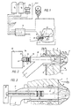
- FIG. 1 is a schematic overview a device according to the invention (partially cut) and FIGS. 2 and 3 each Detail of Fig. 1 on an enlarged scale in different configurations illustrate.
- FIG. 4 a representation analogous to FIG. 3 is a special one Embodiment shown.
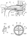
- 5 and 6 each illustrate a cross section to the image plane of FIG. 2 according to further embodiments.
- 7 and 8 illustrate the beam paths according to the invention in a schematic manner.
- Fig. 9 shows a preferred embodiment in a representation analogous to FIG. 3.
- 10 shows in FIG. 4 analog representation of a cross section through a gas supply pipe. 11 relates to a further embodiment.
- a metallurgical vessel 1 for example a refractory lined converter (it could can also be a vacuum vessel or electric furnace or other reactor etc.) to hold one with a slag layer 2 covered steel melt 3, has a height that at Normal filling of the converter 1 is below the molten bath level 4 of the molten steel 3, an opening 5 in a side wall 6, into which a gas supply line 7 is inserted, which with a gas outlet opening 8 on the inside 9 of the side wall 6 of the converter 1 in whose interior 10 opens.
- Gases for example oxygen, nitrogen, air, natural gas or mixtures thereof, and optionally also solids, for example dusty carbon and / or Slag formers or dusts are introduced, the gases mentioned, if appropriate act as carrier gases for the solids.
- the gases are stored in tanks 11 and at Required taken via lines 12.
- the solids are in one or more Conveyor 13 or existing systems removed and by means of a Conveying gas, for example air according to FIG. 1, fed to the converter 1.
- the Composition of the gases or selection and quantity adjustment of the gases can be done with the help of a schematically illustrated valve stand 14.
- the end of the gas supply line is 7 formed as a jacket nozzle 15, through which a central tube 16 of the jacket nozzle surrounding annular gap 17 a hydrocarbon gas, optionally mixed with nitrogen, is introduced into the converter 1, causing it to form a due to cracking reactions annular and the mouth of the jacket nozzle 15 protective approach 18 comes.
- the end of the gas supply line 7 can also be used as a simple pipe (without a protective gas jacket) be trained if durability is not a criterion.
- the central tube 16 opens in the direction of the axis of the jacket nozzle 15 and in alignment this arranged branch pipe 16 ', the one with an aperture 19, which also several side by side can have arranged through openings for the electromagnetic waves, Is provided.
- Behind the aperture 19 is an optical system 20 which acts as a converging lens and behind the optical system 20 one end of an optical waveguide 21, for example a fiber optic cable.
- the optical fiber 21 leads to one electromagnetic wave responsive detector 22, which has an amplifier and a Evaluation electronics 23 is coupled.
- the optical waveguide 21 and the optical system 20 are advantageously in a protective tube 24 built-in.
- Inert branch gas can expediently be introduced into branch line 16 ', etc. over a Line 25, whereby the optical system 20 is kept free of dust.
- gas - without solids - preferably inert gas
- the gas pressure leads to the formation of a cavity 26 filled with this gas, which directly adjoins the ring-shaped projection 18 or is delimited by the latter and the melt surface 27.
- the free passage opening for the gas ensured by the attachment 18 should make up a minimum dimension of approximately 0.2 to 1.0 cm 2 .
- electromagnetic waves especially in the area of visible light and in UV range, emitted. These electromagnetic waves pass through the open aperture or flap 19 and the optical system 20 to the optical waveguide 21 and over this to Detector 22.
- An electronic evaluation unit 23 allows the detection of the natural Type emitted electromagnetic waves equivalent temperature.
- the protective tube 24 projects with the Optical fiber 21 directly into the gas supply line 7, etc. in the area of as Sheath nozzle 15 formed end thereof.
- the protective tube 24 can be flushed with nitrogen be, which is not shown in detail.
- the gas supply line 7 is designed in its end region as a multi-channel nozzle.
- the center of the multi-channel nozzle is the protective tube 24 and the optical system 20 with the Optical fiber 21 is provided.
- the protective tube 24 is peripheral to two at a radial distance annular gap spaces 25, 26 arranged from one another, through which, for example Hydrocarbon gases can be introduced into the converter 1.
- the further annular gap space 28 formed between the two annular gap spaces 28 ′′ and 28 ′′ ′′ is divided by radial webs into a plurality of channels 28 'which, seen in cross section, over each extend a partial circumferential area. Through these channels 28 'other gases, such as oxygen, inert gas or mixtures thereof, introduced into the converter become.
- Fig. 5 shows a measuring arrangement according to the invention with a laser beam device 29, the can be used to carry out a melt analysis.
- the protective tube 24 is used with the optical waveguide 21 slightly off-center of the gas supply line 7.
- the laser beam 30 generated by the laser beam device 29 is so inclined in the direction directed to the gas outlet opening 8 that it is approximately the center of the gas outlet opening 8 penetrates and melt inside the converter at the gas bubble - liquid transition evaporates.
- the electromagnetic waves 31 emitted by the vaporized melt which are indicated in Fig. 5 with wavy arrows are detected by the optical fiber 21 and evaluated via the evaluation electronics 23.
- the laser beam 30 is preferably passed through focused a converging lens, with a focal spot at the opening 5 between gaseous and liquid surface of the melt 3 is formed.
- the device is in the direction of the beam expediently designed to be movable, so that the focal spot can be optimally placed.
- the gas supply line 7 is designed in its end region as a jacket ring nozzle, wherein 17 hydrocarbon gases, inert gases or mixtures through the annular space or annular gap of which are introduced into the converter 1.
- the gas supply line 7 is one Double jacket 32 formed, with the annular space 33 formed by the double jacket Hydrocarbon gases, nitrogen, etc. is introduced.
- the interior of the Gas supply line 7 is longitudinally extending and has radially directed walls 35 divided several times, etc. according to the illustrated embodiment in four approximately the same large rooms 34 shared.
- the laser beam 30 is in the interior of the Converter 1 directed and through a second space 34 protrudes the protective tube 24 with the Lens system with the optical fiber 21.
- Each of the rooms 34 can be different Gases are applied, for example with oxygen or inert gas or mixtures from that.
- a shaft bundle device 43 with which the directed approximately parallel to the optical axis 38 of the optical system 20 electromagnetic waves are focused.
- the oblique to the optical axis 38 of the optical system 20 directed and outside of one of the optical axis 38 of the Optical system 20 drawn limit radius 41 existing electromagnetic waves 39, 40 are not included in this focus.
- the difference between the variant shown in FIG. 7 and the variant shown in FIG. 8 A variant can be seen in the fact that the detector 22 is located directly in the focusing area 44 of the Wave bundle device 43 lies (FIG. 7) and once according to FIG. 8 in the focusing area there is an inlet 45 of an optical waveguide that leads to a detector with evaluation electronics leads.
- the optical system 20 - consists of shaft scattering device 42 and shaft bundle device 43 - in the central tube 16 pivoted, etc. preferably pivotally mounted so that with the optical Axis 38 of the optical system 20 each point in the cross section of the opening 5 can be reached can.
- a movable bearing can be attached to the optical system by means of several attacking pressure medium cylinder 46, which are indicated in Fig. 9 with arrows, or with a gimbal can be realized. This enables the optical axis 38 of the Optical system 20 to align so that even with one-sided growth, the 9, against which the melt 3 can be directed, as a result of which Approach 18 caused measurement falsifications can be avoided.
- the optical system 20 is pivoted until the intensity of the emitting electromagnetic waves when evaluating the same results in a maximum. This is a Criterion that the optical axis of the optical system 20 is actually against the Melt 3 and not against the edge of the neck 18 or the edge of the Opening 5 is directed.
- the movement of the optical system 20 can be performed using a electromechanical drive that automatically adjusts the optical system 20 so that an intensity maximum is formed.
- there can also be axial displacement of the optical system 20 can be provided, as illustrated by the double arrow 47, for which purpose electric motors or pressure medium cylinders can also be provided.
- FIG. 10 shows a cross section through a gas feed pipe, which is analogous to FIG. 4, and which is formed by four concentrically arranged cylinder tubes 24, 48, 49, 50, gaps 51, 52, 53 being provided between the cylinder tubes.
- the innermost tube 24 serves as a gas supply tube for carrying out the measurement. This is where the optical system 20 and the waveguide 21 as well as the detector 22 are located.
- the radially adjoining space 51 between the cylinder tubes 24 and 48 is filled with refractory material 54, but grooves 55 are provided on the outer circumference of the refractory material, which may be made of sheet metal jackets 56 are lined.
- Protective gas for example CH 4 , CH 4 + N 2 etc., is led to the end of the gas supply line 7 via these grooves.
- the radially adjoining annular space 52 is filled with refractory material 54 in the circumferential direction, the remaining three quarters of the annular space 52 are free and are used to supply oxygen or oxygen mixed with other gases.
- the radially outermost annular space 53 in turn serves to supply a protective gas.
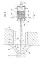
- a gas supply pipe 7 in which the optical system 20 and the signal pickups (optical waveguide 21 and / or detector 22) are installed by a movement mechanism, not shown, which Movements in the directions of arrows 57, 58 shown in FIG. 11 are permitted from above in the melt 3 moves through the surface 59 of the same, wherein it is in the melt 3 Formation of a gas-filled cavity 26 comes.
- the end of the Gas supply pipe 7 may be designed as a jacket nozzle to form a protective gas jacket.
- the measurement can be carried out according to two different basic principles, e.g. once using a pyrometer and once using a spectrometer.
- the evaluation is then carried out using special evaluation electronics that are different for both systems.
- the emitting radiation differs from that for a pure temperature measurement Analysis of the melt.
- a melt analysis uses a laser to generate the considered a spectrum emitted plasma (UV range).
Landscapes
- Physics & Mathematics (AREA)
- Life Sciences & Earth Sciences (AREA)
- Chemical & Material Sciences (AREA)
- Health & Medical Sciences (AREA)
- General Physics & Mathematics (AREA)
- Pathology (AREA)
- Medicinal Chemistry (AREA)
- Analytical Chemistry (AREA)
- Biochemistry (AREA)
- General Health & Medical Sciences (AREA)
- Food Science & Technology (AREA)
- Immunology (AREA)
- Engineering & Computer Science (AREA)
- Spectroscopy & Molecular Physics (AREA)
- Investigating, Analyzing Materials By Fluorescence Or Luminescence (AREA)
- Investigating Or Analysing Materials By Optical Means (AREA)
- Investigating Or Analyzing Materials Using Thermal Means (AREA)
- Control Of High-Frequency Heating Circuits (AREA)
- General Induction Heating (AREA)
- Radiation Pyrometers (AREA)
- Water Treatment By Electricity Or Magnetism (AREA)
- Investigating And Analyzing Materials By Characteristic Methods (AREA)
- Furnace Details (AREA)
- Crucibles And Fluidized-Bed Furnaces (AREA)
- Processing Of Solid Wastes (AREA)
Abstract
Description
Die Erfindung betrifft ein Verfahren zur Bestimmung von aus dem Inneren einer Schmelze, insbesondere einer Metallschmelze, ausgehenden elektromagnetischen Wellen, insbesondere im Bereich des sichtbaren Lichts und des angrenzenden UV-Bereiches und Infrarotbereiches, wobei in der Schmelze durch Einblasen von Gas ein gasgefüllter Hohlraum gebildet wird und von der Schmelze emittierende elektromagnetische Wellen durch das eingeblasene Gas hindurch beobachtet und ausgewertet werden, indem die elektromagnetischen Wellen über ein optisches System einem Detektor zur Bestimmung der Temperatur und/oder der chemischen Zusammensetzung zugeleitet werden, sowie eine Einrichtung zur Durchführung des Verfahrens.The invention relates to a method for determining from the inside of a melt, especially a molten metal, outgoing electromagnetic waves, in particular in the area of visible light and the adjacent UV and infrared range, wherein a gas-filled cavity is formed in the melt by blowing in gas and electromagnetic waves emitting from the melt through the injected gas can be observed and evaluated by passing the electromagnetic waves over a optical system a detector for determining the temperature and / or the chemical Composition will be forwarded, as well as a facility for carrying out the Procedure.
Bei der Stahlerzeugung in einem Konverter oder einem anderen metallurgischen Reaktor durch Frischen von Roheisen bzw. beim Behandeln anderer Schmelzen in einem solchen metallurgischen Gefäß gibt es seit jeher das Bestreben, während des laufenden Behandlungsvorganges möglichst kontinuierlich und schnell über Temperaturwerte der Schmelze und/oder über eine Schmelzenanalyse zu verfügen, um den Behandlungsprozeß möglichst kurz halten zu können und der beabsichtigten Zielanalyse möglichst nahe zu kommen. Schnelligkeit ist insbesondere deswegen erforderlich, weil die chemischen Umsetzreaktionen mit großer Geschwindigkeit ablaufen und die Gefahr besteht, nicht mehr rechtzeitig in den Frischprozeß bzw. Behandlungsprozeß eingreifen zu können. Die extrem rauhen Betriebsbedingungen in solchen Anlagen kommen dieser Aufgabenstellung nicht entgegen. Bei der Stahlerzeugung in einem metallurgischen Reaktor (Konverter, Elektroofen etc.), bei sekundärmetallurgischer Behandlung von Stahlschmelzen bzw. bei anderen nichteisenmetallischen Schmelzen (z.B. Cu, Ni, Al) ist es weiters von Vorteil, die Temperatur bzw. Analyse der Schmelze nach jedem Behandlungsschritt zu kennen.When producing steel in a converter or other metallurgical reactor by refreshing pig iron or treating other melts in one metallurgical vessel has always been striving while running Treatment process as continuously and quickly as possible via temperature values of the Melt and / or to have a melt analysis to the treatment process to keep it as short as possible and as close as possible to the intended target analysis come. Speed is particularly important because the chemical Implementation reactions run at high speed and there is no longer any danger to be able to intervene in time in the fresh process or treatment process. The extreme Rough operating conditions in such systems do not meet this task opposite. When producing steel in a metallurgical reactor (converter, electric furnace etc.), in the secondary metallurgical treatment of steel melts or in others non-ferrous metal melts (e.g. Cu, Ni, Al), it is also advantageous to adjust the temperature or analysis of the melt after each treatment step.
Zur Lösung dieser Problematik ist beispielsweise versucht worden, aus der spektralen Analyse der Konverterflamme oder aus ihrer Absorptionswirkung gegenüber monochromatischem Licht bestimmter Wellenlänge einen Hinweis für den richtigen Zeitpunkt der Beendigung des Frischprozesses zu erhalten. Die stark wechselnden Blasbedingungen und die schäumende Schlacke auf dem Schmelzenbad sowie der hohe Staubgehalt im Abgas erlauben jedoch keinen hinreichend genauen Rückschluß auf Badtemperatur und Schmelzenanalyse.To solve this problem, attempts have been made, for example, from spectral analysis the converter flame or from its absorption effect compared to monochromatic Light of a certain wavelength indicates the right time for the termination of the To maintain the fresh process. The strongly changing blowing conditions and the foaming However, slag on the melt pool and the high dust content in the exhaust gas allow no sufficiently precise conclusion on bath temperature and melt analysis.
Weiters ist zur Temperaturmessung vorgeschlagen worden (DE-B - 14 08 873), in die feuerfeste Zustellung des Konverters gekapselte Thermoelemente einzusetzen, die in den Konverterinnenraum vorstehen und in Arbeitsstellung des Konverters unter dem Badspiegel der zu frischenden Schmelze liegen. Die Haltbarkeit dieser Thermoelemente war jedoch unzureichend; die notwendigerweise starke Kühlung der Meßeinrichtung beeinträchtigt zudem die Meßergebnisse.Furthermore, it has been proposed for temperature measurement (DE-B - 14 08 873), in which use refractory delivery of the converter encapsulated thermocouples, which in the Project the converter interior and in the working position of the converter under the bathroom mirror of the melt to be refreshed. However, the durability of these thermocouples was insufficient; the necessarily strong cooling of the measuring device is impaired also the measurement results.
Weiters ist es bekannt, die Temperatur einer Schmelze zu einem bestimmten Zeitpunkt mittels einer in die Schmelze eintauchenden Lanze zu bestimmen. Dieses Verfahren ist bei Anwendung der Stahlherstellung in einem Konverter nachteilig, denn hierzu muß der Konverter gekippt und wieder aufgerichtet werden, was einen Temperaturverlust des Stahlbades bis zu 40°C verursacht. Das Verfahren ist weiters zeitintensiv, denn zunächst muß vor dem Kippen des Konverters die Blaslanze ausgefahren werden, und es muß nach der Durchführung der Messung der Konverter wieder aufgerichtet werden, worauf erst - falls notwendig - die Blaslanze eingefahren und weiter geblasen werden kann. Weitere Nachteile sind, daß der Meßpunkt in der Schmelze nur willkürlich gewählt werden kann, also kaum reproduzierbar ist. Weiters ist auch die Eintauchtiefe der Sonde nicht genau feststellbar und ebenfalls kaum reproduzierbar.Furthermore, it is known to use the temperature of a melt at a specific point in time of a lance immersed in the melt. This procedure is with Use of steel production in a converter disadvantageous, because the Tilt converter and be erected again, which results in a temperature loss of the Steel bath caused up to 40 ° C. The process is also time-consuming, because first of all, must Before the converter is tilted, the blowing lance must be extended and it must be after the Carrying out the measurement of the converter can be erected again, after which - if necessary - the blowing lance can be retracted and blown on. Other disadvantages are that the measuring point in the melt can only be chosen arbitrarily, so hardly is reproducible. Furthermore, the immersion depth of the probe cannot be determined exactly also hardly reproducible.
Wesentlich komplizierter gestaltet sich noch die Bestimmung einer chemischen Analyse der Schmelze. Hierfür ist es bekannt, Proben zu entnehmen, u.zw. mit Hilfe von in die Schmelze eintauchenden Lanzen. Für die Stahlerzeugung im Konverter ergeben sich hierdurch Nachteile, da eine solche Probenahme ebenfalls zeitintensiv ist - der Konverter muß in diesem Fall ebenfalls gekippt werden (ausgenommen bei senkrechter Sublanzenmessung) - und die Probe muß ins Labor gebracht werden.The determination of a chemical analysis of the is much more complicated Melt. For this purpose it is known to take samples, etc. with the help of in the melt immersed lances. This results in steel production in the converter Disadvantages, since such sampling is also time-consuming - the converter must be in this Case also be tilted (except for vertical sublance measurement) - and the Sample must be brought to the laboratory.
Es ist bekannt, bei der Herstellung von Stahl im Konverter eine Kohlenstoff-Schnellbestimmung durchzuführen, u.zw. durch Messung des Haltepunktes der Temperatur und des C-Gehaltes. Hierdurch gelingt es jedoch nur, das C-Äquivalent zu erfassen, so daß zur Berechnung des tatsächlichen Kohlenstoffgehaltes einige der in der Schmelze vorhandenen Begleitelemente berücksichtigt werden müssen.It is known that a quick carbon determination is made in the production of steel in the converter to carry out, etc. by measuring the stop point of the temperature and the C content. This, however, only succeeds in capturing the C equivalent, so that for Calculating the actual carbon content of some of the ones present in the melt Accompanying elements must be taken into account.
Weiters ist es bekannt, mit Hilfe von Sublanzen Kohlenstoff- und Sauerstoffaktivitätsbestimmungen sowie Probenahmen und Temperaturmessungen in einem Konverter durchzuführen. Dies ist jedoch insoferne nachteilig, als die Sublanzeneinrichtungen selbst (und auch die Proben) sehr teuer sind, einem unverhältnismäßig großen Verschleiß unterliegen und nur bei flüssigen Schlacken gegen Ende des Blasprozesses eingesetzt werden können. Furthermore, it is known with the help of carbon and sublancies Oxygen activity determinations as well as sampling and temperature measurements in one Perform converter. However, this is disadvantageous in that the sublance devices themselves (and also the samples) are very expensive, a disproportionate amount of wear subject and are only used for liquid slags towards the end of the blowing process can.
Aus der EP-B - 0 162 949 ist ein Verfahren zur Beobachtung der Schlackenbildung in einem Blasstahlkonverter bekannt, bei dem die im Konverterraum von der Schlackenoberfläche emittierte Lichtstrahlung herangezogen wird. Das Licht wird hierbei photoelektrisch in Signale umgewandelt und verarbeitet, wobei Veränderungen der Signale als Kriterium der Schaumschlackenbildung gewertet werden. Die in der Seitenwand des Konverters eingesetzten Rezeptoren befinden sich oberhalb des Schlacken-/Schmelzenbades und sind für die Messung der Schmelzenbadtemperatur und der Schmelzenzusammensetzung nicht geeignet.EP-B-0 162 949 describes a method for monitoring the formation of slag in one Blown steel converter known in which the converter room from the slag surface emitted light radiation is used. The light becomes photoelectric in Signals are converted and processed, with changes in the signals as a criterion of Foam slag formation can be assessed. The one in the side wall of the converter Receptors used are located above the slag / melt bath and are for the measurement of the melt bath temperature and the melt composition is not suitable.
Aus der US-A - 4,830,601 ist ein Verfahren und die Vorrichtung zur spektralanalytischen Auswertung des emittierten Lichts aus dem Zentrum einer Brennerflamme bekannt. Dabei wird die Zufuhr von Brennstoff und Verbrennungsluft anhand des Lichtspektrums überprüft. Über Glasfaserleitungen wird emittiertes Licht einer Auswerteelektronik zugeführt und die Verbrennungsluft- bzw. Brennstoffzufuhr entsprechend der ermittelten Gasanalyse geregelt.From US-A-4,830,601 is a method and the device for spectral analysis Evaluation of the emitted light from the center of a burner flame is known. Here the supply of fuel and combustion air is checked based on the light spectrum. Emitted light is fed to evaluation electronics via fiber optic cables and the Combustion air or fuel supply regulated according to the determined gas analysis.
Eine ähnliche Anordnung zur Temperaturmessung bei einem Verfahren zur Reduktionsgaserzeugung in einem Hochtemperaturreaktor bei erhöhtem Betriebsdruck ist der DE-A - 40 25 909 zu entnehmen.A similar arrangement for temperature measurement in a method for Reduction gas generation in a high-temperature reactor at increased operating pressure is the DE-A - 40 25 909 can be found.
Aus der EP-A - 0 215 483 ist es bekannt, die chemische Zusammensetzung des Eisens zu eruieren, indem Sauerstoff oder ein Sauerstoff enthaltendes Gas von oben auf die Oberfläche von geschmolzenem Eisen geblasen wird, wobei von der Schmelzenoberfläche ausgehende Strahlen in einem Spektrometer zur Bestimmung der chemischen Zusammensetzung des Eisens detektiert werden.From EP-A - 0 215 483 it is known to determine the chemical composition of iron determine by placing oxygen or a gas containing oxygen on the surface from above is blown by molten iron, starting from the melt surface Radiation in a spectrometer to determine the chemical composition of the Iron can be detected.
Aus der US-A - 4,619,533 und der EP-A - 0 362 577 sind Verfahren der eingangs beschriebenen Art bekannt, wobei im ersteren Fall von der Metallschmelze ausgehende Strahlung über einen Lichtwellenleiter einem Detektor zugeleitet wird. Gemäß der EP-A - 0 362 577 wird Laserlicht auf die Metalloberfläche fokussiert und hierbei ein Plasma erzeugt. Das von der Metalloberfläche emittierte Plasmalicht wird über ein Linsensystem und einen Lichtwellenleiter einem Spektrometer zur Elementanalyse zugeführt. Das Linsensystem weist verstellbare Linsen auf. Die Linsen werden so eingestellt, daß das Intensitätsverhältnis zweier Eisenlinien, u.zw. die Intensität einer Atomlinie und die Intensität einer Ionenlinie minimal ist.US-A-4,619,533 and EP-A-0 362 577 are methods of the beginning described type known, wherein in the former case starting from the molten metal Radiation is fed to a detector via an optical waveguide. According to EP-A - 0 362 577, laser light is focused on the metal surface and a plasma is generated. The plasma light emitted from the metal surface is passed through a lens system and one Optical waveguide fed to a spectrometer for element analysis. The lens system points adjustable lenses. The lenses are adjusted so that the intensity ratio of two Iron lines, etc. the intensity of an atomic line and the intensity of an ionic line minimal is.
Das Einblasen von Gas zur Bildung eines gasgefüllten Hohlraumes erfolgt bei einem Verfahren der eingangs beschriebenen Art, d.h. bei Erfassen von aus dem Inneren einer Schmelze ausgehenden elektromagnetischen Wellen, vorteilhaft über eine Wandöffnung eines die Metallschmelze aufnehmenden metallurgischen Gefäßes, wobei diese Öffnung unterhalb des Normalbadspiegels liegen muß. Im Übergangsbereich dieser Öffnung des metallurgischen Gefäßes zur Schmelze hin, d.h. im Randbereich dieser Öffnung, gehen selbst bei sehr kleiner Öffnung Reflexionen der von der Schmelze emittierenden elektiomagnetischen Wellen aus, die zu Meßwertverfälschungen führen. Kommt es zu einer pilzförmigen Ansatzbildung aus erstarrter Schmelze infolge eingeblasenen Gases, stellt der Ansatz, der die Form eines den Randbereich der Öffnung über ihren ganzen Umfang umgebenden und in Richtung Schmelze gerichteten Wulstes aufweist, trotz seiner Schutzfunktion für die Öffnung einen Störfaktor dar und verändert stets seine Größe und Lage, wodurch Strahlung, die von der Oberfläche des Ansatzes oder vom Übergangsbereich des Ansatzes zur Schmelze ausgeht, das Meßergebnis verfälscht. Es hat sich gezeigt, daß eine genaue Messung nur dann durchgeführt werden kann, wein ausschließlich Strahlung von der Schmelzenoberfläche empfangen und dem Detektor zugeleitet wird. Reflexionen vom Randbereich der Öffnung bzw. vom Ansatz wirken stark störend, d.h. meßwertverfälschend, ohne daß dies durch andere Anzeichen bemerkbar ist.The gas is blown in to form a gas-filled cavity in one Methods of the type described in the introduction, i.e. when capturing from inside one Melt outgoing electromagnetic waves, advantageously through a wall opening the metallurgical vessel receiving the molten metal, this opening below of the normal bath level. In the transition area of this opening of the metallurgical Vessel towards the melt, i.e. in the edge area of this opening, go even at very small Opening reflections of the electromagnetic waves emitting from the melt, which lead to falsified measurements. If there is a mushroom-like build-up solidified melt as a result of injected gas, the approach that takes the form of a Edge area of the opening around its entire circumference and towards the melt directed bead has a disturbing factor despite its protective function for the opening and always changes its size and location, causing radiation from the surface of the Approach or starting from the transition area of the approach to the melt, the measurement result adulterated. It has been shown that an accurate measurement can only be carried out if wine only receive radiation from the melt surface and the detector is forwarded. Reflections from the edge area of the opening or from the base have a strong effect disturbing, i.e. falsifies the measured value, without this being noticeable by other signs.
Die Erfindung bezweckt die Vermeidung dieser Nachteile und Schwierigkeiten und stellt sich die Aufgabe, ein Verfahren der eingangs beschriebenen Art sowie eine Einrichtung zur Durchführung des Verfahrens zu schaffen, welche die Ermittlung gewünschter Meßwerte einer Schmelze (wie z.B. Stahl, rostfreier Stahl, Ferrolegierungen und Schmelzen von Nichteisenmetallen) praktisch ohne Zeitverzögerung auf einfache Art und Weise und insbesondere kontinuierlich sowie auch bei viskosen bis trockenen Schlacken ermöglichen. Hierbei sollen Meßwertverfälschungen, die durch das Meßverfahren selbst und die durch den rauhen Hüttenwerksbetrieb bedingt sind, zuverlässig vermieden werden können, wobei Meßwertverfälschungen auch bei sehr klein gehaltenem Hohlraum in der Schmelze ausgeschlossen werden sollen.The invention aims at avoiding these disadvantages and difficulties and presents itself the task, a method of the type described above and a device for Implementation of the method to create the determination of desired measured values a melt (such as steel, stainless steel, ferroalloys and smelting of Non-ferrous metals) practically without time delay in a simple way and in particular continuously and also with viscous to dry slags. In this case, falsifications of measured values caused by the measuring method itself and by the rough metallurgical operation are caused, can be reliably avoided, whereby Falsification of measured values even with a very small cavity in the melt should be excluded.
Diese Aufgabe wird erfindungsgemäß dadurch gelöst, daß schräg zur optischen Achse des optischen Systems gerichtete und vom Randbereich des Hohlraumes ausgehende elektromagnetische Wellen von einer Detektierung ausgeschlossen werden, indem die emittierenden elektromagnetischen Wellen von schräg zur optischen Achse des optischen Systems gerichteten und außerhalb eines von der optischen Achse des optischen Systems gezogenen Grenzradius vorhandenen elektromagnetischen Wellen befreit werden, indem diese elektromagnetischen Wellen in einer Wellenstreueinrichtung des optischem Systems, wie einem Zerstreuungs- und Sammellinsensystem, von der optischen Achse des optischen Systems weggebrochen werden und nur etwa parallel zur optischen Achse des optischen Systems gerichtete elektromagnetische Wellen zu einem dem optischen System nachgeordneten Detektor gelangen.This object is achieved in that obliquely to the optical axis of the optical system directed and starting from the edge region of the cavity electromagnetic waves can be excluded from detection by the emitting electromagnetic waves from oblique to the optical axis of the optical System directed and outside of one of the optical axis of the optical system drawn limit radius existing electromagnetic waves are freed by this electromagnetic waves in a wave scattering device of the optical system, such as a diverging and converging lens system, from the optical axis of the optical Systems are broken away and only approximately parallel to the optical axis of the optical Systems directed electromagnetic waves to the optical system downstream detector.
Vorzugsweise wird das optische System unter Ausrichtung seiner optischen Achse gegenüber dem Hohlraum bewegt, u.zw. so lange bewegt, bis die Intensität der emittierenden elektromagnetischen Wellen bei der Auswertung derselben ein Maximum ergibt.Preferably, the optical system is aligned with its optical axis moved the cavity, etc. moved until the intensity of the emitting electromagnetic waves when evaluating the same results in a maximum.
Gemäß einer bevorzugten Ausführungsform ist der Wellenstreueinrichtung eine Wellenbündeleinrichtung, wie eine Sammellinse oder ein Sammellinsensystem, nachgeordnet und werden die etwa parallel zur optischen Achse des optischen Systems gerichteten elektromagnetischen Wellen von der Wellenbündeleinrichtung fokussiert und dem Detektor direkt oder über einen Lichtwellenleiter zugeleitet, die schrägen und außerhalb eines Grenzradius vorhandenen Wellen werden jedoch von dieser Fokussierung nicht mitumfaßt.According to a preferred embodiment, the wave scattering device is a Shaft bundle device, such as a converging lens or a converging lens system, arranged downstream and are directed approximately parallel to the optical axis of the optical system focused electromagnetic waves from the wave bundle device and the detector fed directly or via an optical fiber, the oblique and outside of one Waves present at the limit radius are not included in this focusing.
Eine weitere bevorzugte Ausführungsform ist dadurch gekennzeichnet, daß sowohl die Wellenstreueinrichtung als auch die nachgeordnete Strahlenbündeleinrichtung unter Ausrichtung ihrer optischen Achse gegenüber dem Hohlraum bewegt werden, bis die Intensität der emittierenden elektromagnetischen Wellen bei der Auswertung derselben ein Maximum ergibt. Hierdurch gelingt es, auch bei einer besonders starken und/oder bei einer stark einseitigen Ansatzbildung, d.h. bei Schmelzen mit besonders starker Neigung zur Ansatzbildung oder bei Hohlräumen in der Schmelze mit kleinen Durchmessern, noch optimale Meßergebnisse zu erhalten.Another preferred embodiment is characterized in that both the Wave scattering device as well as the subordinate radiation beam device below Alignment of their optical axis with respect to the cavity are moved until the Intensity of the emitting electromagnetic waves when evaluating the same Maximum results. This makes it possible, even with a particularly strong and / or one strongly one-sided approach formation, i.e. for melts with a particularly strong tendency to Formation or in the case of cavities in the melt with small diameters, still to obtain optimal measurement results.
Zur Durchführung einer Schmelzenanalyse wird zweckmäßig über den gasgefüllten Hohlraum der Schmelze Energie zugeführt und durch die zugeführte Energie ein Teil der Schmelze verdampft, wobei vorteilhaft das eingeblasene Gas mit der Schmelze eine chemische Reaktion eingeht, die zum Verdampfen eines Teiles der Schmelze führt.To carry out a melt analysis, it is expedient to use the gas-filled cavity energy supplied to the melt and part of the melt by the energy supplied evaporates, advantageously the blown gas with the melt a chemical reaction incoming, which leads to the evaporation of part of the melt.
Zum Schutz des Meßvorganges wird zweckmäßig das zur Bildung des gasgefüllten Hohlraumes eingeblasene Gas an der Eintrittsstelle in die Schmelze von einem Gasmantel oder mehreren Gasmänteln, der bzw. die ein kohlenwasserstoffhältiges Schutzmedium, vorzugsweise gemischt mit Inertgas, enthält bzw. enthalten, umgeben. Hierdurch kommt es zur Ausbildung eines die Gaszuführung sichernden Ansatzes an erstarrter Schmelze, der auch eine wesentliche Schonung der für die Durchführung der Messung erforderlichen Einrichtung sowie lange Standzeiten derselben bewirkt. To protect the measuring process, it is useful to form the gas-filled one Cavity injected gas at the point of entry into the melt from a gas jacket or several gas jackets containing a protective medium containing hydrocarbons, preferably mixed with inert gas, contains or contain, surrounded. This is where it comes from to form a gas supply securing approach to solidified melt, which also a substantial protection of the equipment required to carry out the measurement and long service life of the same.
Eine Vereinfachung und Beschleunigung des Verfahrens ergibt sich, wenn die Bestimmung der Temperatur bzw. chemischen Analyse der Schmelze kombiniert wird mit vorgerechneten bzw. gemessenen Parametern, wie einer Kohlenstoffbilanz der Abgasanalyse oder einer groben Berechnung der Analyse der Schmelze zum Zeitpunkt der Messung, und weiters, wenn nur der Gehalt einzelner Elemente der Schmelze, wie z.B. bei Eisenschmelzen der Mn-, Cr-, C-Gehalt etc., ermittelt wird und daraus der Gehalt der anderen in der Schmelze und auch Schlackenschmelze vorhandenen Elemente bzw. Verbindungen berechnet wird.A simplification and acceleration of the procedure results when the determination the temperature or chemical analysis of the melt is combined with pre-calculated or measured parameters, such as a carbon balance of the exhaust gas analysis or rough calculation of the analysis of the melt at the time of measurement, and further, if only the content of individual elements of the melt, e.g. with iron melting the Mn Cr, C content etc., is determined and from this the content of the others in the melt and also Slag melt existing elements or compounds is calculated.
Die Genauigkeit des erfindungsgemäßen Verfahrens läßt sich dadurch steigern, daß während der Messung im Hohlraum bzw. knapp davor durch Einleiten eines Gasgemisches eine Temperatur eingestellt wird, die möglichst nahe an der Ist-Temperatur der Schmelze liegt.The accuracy of the method according to the invention can be increased in that during the measurement in the cavity or just before by introducing a gas mixture Temperature is set that is as close as possible to the actual temperature of the melt.
Vorzugsweise wird mit einem Gas oder mit mehreren verschiedenen Gasen, die in die Schmelze eingeleitet werden, die chemische Analyse der Schmelze gezielt verändert und die Schmelze bzw. Schmelze und Schlacke durchmischt.Preferably, one or more different gases are used in the Melt are initiated, the chemical analysis of the melt is specifically changed and the Melt or melt and slag mixed.
Nach einer bevorzugten Ausführungsform wird der gasgefüllte Hohlraum an der Schmelzenoberfläche gebildet, indem z.B. eine Gaszuführungsleitung mit Optik, Lichtwellenleiter, Detektor etc. in die Schmelze eintaucht.According to a preferred embodiment, the gas-filled cavity on the Melt surface formed by e.g. a gas supply line with optics, Optical fiber, detector etc. immersed in the melt.
Eine Einrichtung zur Durchführung des Verfahrens mit
- einem eine Schmelze aufnehmenden Gefäß,
- einer zu einer Öffnung des Gefäßes führenden Gaszuführungsleitung mit einer gegen Öffnung und damit gegen die Schmelze gerichteten Gasaustrittsöffnung,
- einem optischen System zur Beobachtung der Gasaustrittsöffnung,
- einem Detektor zur Registrierung von aus der Schmelze emittierenden elektromagnetischen Wellen und
- gegebenenfalls mit einem die elektromagnetischen Wellen zum Detektor führenden
Wellenleiter,
ist gekennzeichnet durch - eine optische Wellenstreueinrichtung, wie ein Zerstreuungs-Sammellinsensystem, wobei vorzugsweise
- eine gegenüber dem metallurgischen Gefäß bewegbare, vorzugsweise schwenkbare, Anordnung des optischen Systems vorgesehen ist.
- a vessel holding a melt,
- a gas supply line leading to an opening of the vessel with a gas outlet opening directed towards the opening and thus against the melt,
- an optical system for observing the gas outlet opening,
- a detector for registering electromagnetic waves emitting from the melt and
- optionally with a waveguide leading the electromagnetic waves to the detector,
is characterized by - an optical wave scattering device, such as a diverging lens system, preferably
- an arrangement of the optical system that is movable, preferably pivotable, relative to the metallurgical vessel is provided.
Eine bevorzugte Ausführungsform ist gekennzeichnet durch
- eine der Wellenstreueinrichtung nachgeordnete Wellenbündeleinrichtung, wie eine Sammellinse oder ein nachgeordnetes Sammellinsensystem, und
- einen im Fokussierungsbereich der Wellenbündeleinrichtung liegenden Detektor oder einen dort angeordneten und zu einem Detektor führenden Lichtwellenleiter.
- a shaft bundle device downstream of the wave scattering device, such as a converging lens or a downstream converging lens system, and
- a detector lying in the focusing area of the wave bundle device or an optical waveguide arranged there and leading to a detector.
Vorteilhaft ist ein Schutzrohr für das optische System mit einer Gasspülung, insbesondere einer das Linsensystem an der Frontseite reinigenden Gasspülung, vorgesehen. Dies ist insbesondere dann erforderlich, falls durch die Gaszuführungsleitung Feststoffe, wie beispielsweise Schlackenbildner, Stäube, insbesondere Kohlenstaub, etc., zwischen den Meßzeitpunkten in die Schmelze eingeblasen werden.A protective tube for the optical system with a gas purging, in particular, is advantageous a gas purging that cleans the lens system on the front. This is especially necessary if solids, such as through the gas supply line for example, slag formers, dusts, in particular coal dust, etc., between the Measurement times are blown into the melt.
Eine weitere bevorzugte Ausführungsform ist dadurch gekennzeichnet, daß die Wellenstreueinrichtung gegenüber der gegen die Schmelze gerichteten Gasaustrittsöffnung schwenkbar ist, wobei der Schnittpunkt der optischen Achse der Wellenstreueinrichtung mit der Querschnittsfläche der Gasaustrittsöffnung innerhalb deren Querschnittsfläche verstellbar ist.Another preferred embodiment is characterized in that the Wave scattering device opposite the gas outlet opening directed against the melt is pivotable, the intersection of the optical axis of the wave scattering device with the cross-sectional area of the gas outlet opening is adjustable within its cross-sectional area is.
Zweckmäßig sind sowohl die Wellenstreueinrichtung als auch die Wellenbündeleinrichtung schwenkbar gelagen, wobei vorteilhaft die schwenkbare Lagerung als kardanische Lagerung ausgebildet ist.Both the wave scattering device and the wave bundle device are expedient pivoted, advantageously the pivotable mounting as a gimbal is trained.
Entweder ist im Fokussierungsbereich der Wellenbündeleinrichtung ein Einlaß eines Lichtwellenleiters angeordnet oder ist im Fokussierungsbereich der Wellenbündeleinrichtung der Detektor angeordnet.Either there is an inlet in the focusing area of the wave bundle device Optical waveguide arranged or is in the focusing area of the wave bundle device the detector is arranged.
Eine zweckmäßige Ausführungsform ist dadurch gekennzeichnet, daß das Ende der Gaszuführungsleitung als Zwei- oder Mehrrohrdüse ausgebildet ist, deren Mantelringraum bzw. -räume an eine ein Kohlenwasserstoffgas zuführende Leitung anschließbar ist (sind). Hierdurch kommt es zur Ausbildung eines Ansatzes von erstarrter Schmelze, der die Gaseintrittsöffnung umgibt, so daß die Mehrrohrdüse gut geschützt am Gefäß, d.h. in der Ausmauerung des Gefäßes angeordnet ist.An expedient embodiment is characterized in that the end of the Gas supply line is designed as a two- or multi-tube nozzle, the jacket annulus or rooms can be connected to a line supplying a hydrocarbon gas. This leads to the formation of an approach of solidified melt, which the Gas inlet opening surrounds, so that the multi-tube nozzle well protected on the vessel, i.e. in the Brick lining of the vessel is arranged.
Vorzugsweise ist das Ende der Gaszuführungsleitung von einer Mehrkanaldüse gebildet, deren Düsenöffnungen an eine oder mehrere Zuführungsleitungen für Kohlenwasserstoff, Kohlenmonoxid, Kohlendioxid, Inertgas, Dampf, Öl oder Wasser bzw. Mischungen davon anschließbar sind. Hierbei gelingt es, die Manteldüsenhaltbarkeit und Genauigkeit der Messung durch Einstellung der Menge und/oder Zusammensetzung der durch die Ringspalte eingeleiteten Gase oder Flüssigkeiten während des Durchführens des Meßverfahrens und generell zu optimieren.The end of the gas supply line is preferably formed by a multi-channel nozzle, whose nozzle openings to one or more feed lines for hydrocarbon, Carbon monoxide, carbon dioxide, inert gas, steam, oil or water or mixtures thereof can be connected. Here, the jacket nozzle durability and accuracy of the Measurement by adjusting the amount and / or composition of the ring gaps introduced gases or liquids during the execution of the measuring procedure and generally optimize.
Gemäß einer bevorzugten Ausführungsform ist, wie aus der EP-A - 0 362 577 an sich bekannt, eine gegen die Gasaustrittsöffnung der Gaszuführungsleitung gerichtete Laserstrahleinrichtung vorgesehen, wobei zweckmäßig der Laserstrahleneinrichtung eine Fokussiereinrichtung zugeordnet ist.According to a preferred embodiment, as per EP-A-0 362 577 per se known, directed against the gas outlet opening of the gas supply line Laser beam device is provided, wherein the laser beam device expediently Focusing device is assigned.
Vorzugsweise ist eine in die Schmelze eintauchende Gaszuführungsleitung mit Wellenstreueinrichtung vorgesehen.A gas supply line immersed in the melt is preferably included Wave scattering device provided.
Ein Verfahren zum Betrieb einer erfindungsgemäßen Einrichtung ist dadurch gekennzeichnet, daß zum Schutz des in das Gefäß mündenden Teiles der Einrichtung die Zufuhr des Schutzmediums geregelt wird, indem mit zunehmendem Angriff der Schmelze, d.h. mit steigender Temperatur bzw. Überhitzung der Schmelze, die Zufuhr von kohlenwasserstoffhältigem Schutzmedium kontinuierlich oder stufenweise verstärkt wird.A method for operating a device according to the invention is characterized in that that to protect the part of the device opening into the vessel, the supply of the Protection medium is regulated by increasing attack of the melt, i.e. With increasing temperature or overheating of the melt, the supply of hydrocarbon-containing protective medium is continuously or gradually reinforced.
Die Erfindung ist nachfolgend anhand mehrerer in der Zeichnung schematisch dargestellter Ausführungsbeispiele näher erläutert, wobei Fig. 1 eine schematische Gesamtübersicht über eine erfindungsgemäße Einrichtung (teilweise geschnitten) und die Fig. 2 und 3 jeweils ein Detail der Fig. 1 in vergrößertem Maßstab in jeweils unterschiedlichen Ausgestaltungen veranschaulichen. In Fig. 4 ist in zu Fig. 3 analoger Darstellung eine spezielle Ausführungsform dargestellt. Die Fig. 5 und 6 veranschaulichen jeweils einen Schnitt quer zur Bildebene der Fig. 2 gemäß weiteren Ausführungsformen. Die Fig. 7 und 8 veranschaulichen in schematischer Weise die erfindungsgemäßen Strahlengänge. Fig. 9 zeigt eine bevorzugte Ausführungsform in zu Fig. 3 analoger Darstellung. Fig. 10 zeigt in zu Fig. 4 analoger Darstellung einen Querschnitt durch ein Gaszuführungsrohr. Fig. 11 betrifft eine weitere Ausführungsform.The invention is described below with reference to several schematically in the drawing Embodiments explained in more detail, wherein Fig. 1 is a schematic overview a device according to the invention (partially cut) and FIGS. 2 and 3 each Detail of Fig. 1 on an enlarged scale in different configurations illustrate. In FIG. 4, a representation analogous to FIG. 3 is a special one Embodiment shown. 5 and 6 each illustrate a cross section to the image plane of FIG. 2 according to further embodiments. 7 and 8 illustrate the beam paths according to the invention in a schematic manner. Fig. 9 shows a preferred embodiment in a representation analogous to FIG. 3. 10 shows in FIG. 4 analog representation of a cross section through a gas supply pipe. 11 relates to a further embodiment.
Ein metallurgisches Gefäß 1, beispielsweise ein feuerfest ausgekleideter Konverter (es könnte
auch ein Vakuumgefäß oder Elektroofen oder anderer Reaktor etc. sein) zur Aufnahme einer
mit einer Schlackenschicht 2 bedeckten Stahlschmelze 3, weist in einer Höhe, die bei
Normalfüllung des Konverters 1 unter dem Schmelzenbadspiegel 4 der Stahlschmelze 3 liegt,
eine Öffnung 5 in einer Seitenwand 6 auf, in die eine Gaszuführungsleitung 7 eingesetzt ist,
die mit einer Gasaustrittsöffnung 8 an der Innenseite 9 der Seitenwand 6 des Konverters 1 in
dessen Innenraum 10 mündet. Über die Gaszuführungsleitung 7 können unterschiedliche
Gase, beispielsweise Sauerstoff, Stickstoff, Luft, Erdgas oder Gemische davon, sowie
gegebenenfalls auch Feststoffe, beispielsweise staubförmiger Kohlenstoff und/oder
Schlackenbildner bzw. Stäube, eingebracht werden, wobei die genannten Gase gegebenenfalls
für die Feststoffe als Trägergase fungieren. Die Gase werden in Tanks 11 gespeichert und bei
Bedarf über Leitungen 12 entnommen. Die Feststoffe werden in einem oder in mehreren
Fördergefäßen 13 gelagen bzw. vorhandenen Systemen entnommen und mittels eines
Fördergases, beispielsweise Luft gemäß Fig. 1, dem Konverter 1 zugeleitet. Die
Zusammensetzung der Gase bzw. Auswahl und Mengeneinstellung der Gase kann mit Hilfe
eines schematisch dargestellten Ventilstandes 14 erfolgen.A metallurgical vessel 1, for example a refractory lined converter (it could
can also be a vacuum vessel or electric furnace or other reactor etc.) to hold one
with a slag layer 2 covered
Gemäß der in Fig. 2 dargestellten Ausführungsform ist das Ende der Gaszuführungsleitung 7
als Manteldüse 15 ausgebildet, wobei durch den ein Zentralrohr 16 der Manteldüse
umgebenden Ringspalt 17 ein Kohlenwasserstoffgas, gegebenenfalls gemischt mit Stickstoff,
in den Konverter 1 eingeleitet wird, wodurch es infolge Crackreaktionen zur Ausbildung eines
ringförmigen und die Mündung der Manteldüse 15 schützenden Ansatzes 18 kommt. Das
Ende der Gaszuführungsleitung 7 kann auch als einfaches Rohr (ohne Schutzgasmantel)
ausgebildet sein, wenn die Haltbarkeit kein Kriterium darstellt.According to the embodiment shown in FIG. 2, the end of the gas supply line is 7
formed as a
In das Zentralrohr 16 mündet ein in Richtung der Achse der Manteldüse 15 und fluchtend zu
dieser angeordnetes Zweigrohr 16', das mit einer Blende 19, die auch mehrere nebeneinander
angeordnete Durchtrittsöffnungen für die elektromagnetischen Wellen aufweisen kann,
ausgestattet ist. Hinter der Blende 19 ist ein als Sammellinse wirkendes optisches System 20
und hinter dem optischen System 20 ein Ende eines Lichtwellenleiters 21, beispielsweise
eines Glasfaserleiters, vorgesehen. Der Lichtwellenleiter 21 führt zu einem auf
elektromagnetische Wellen ansprechenden Detektor 22, der mit einem Verstärker und einer
Auswerteelektronik 23 gekoppelt ist.In the
Der Lichtwellenleiter 21 und das optische System 20 sind vorteilhaft in einem Schutzrohr 24
eingebaut. In die Zweigleitung 16' läßt sich zweckmäßig inertes Gas einleiten, u.zw. über eine
Leitung 25, wodurch eine Freihaltung des optischen Systems 20 von Staub gelingt.The
Die Funktion der Einrichtung ist folgende:The function of the facility is as follows:
Zur Durchführung einer Temperaturmessung wird durch die Gaszuführungsleitung 7 lediglich
Gas - ohne Feststoffe -, vorzugsweise inertes Gas, in den Konverter 1 eingeblasen. Hierbei
kommt es durch den Gasdruck zur Ausbildung eines von diesem Gas gefüllten Hohlraumes
26, der unmittelbar an den ringförmig ausgebildeten Ansatz 18 anschließt bzw. von diesem
und der Schmelzenoberfläche 27 begrenzt ist. Die durch den Ansatz 18 sichergestellte freie
Durchtrittsöffnung für das Gas soll ein Mindest-Ausmaß von etwa 0,2 bis 1,0 cm2 ausmachen.To carry out a temperature measurement, only gas - without solids -, preferably inert gas, is blown into the converter 1 through the
Von der Schmelzenoberfläche 27 der den gasgefüllten Hohlraum 26 begrenzenden Schmelze
3 werden elektromagnetische Wellen, insbesondere im Bereich des sichtbaren Lichts und im
UV-Bereich, emittiert. Diese elektromagnetischen Wellen gelangen über die geöffnete Blende
oder Klappe 19 und das optische System 20 zum Lichtwellenleiter 21 und über diesen zum
Detektor 22. Eine Auswerteelektronik 23 gestattet die Feststellung der zu den auf natürliche
Art emittierten elektromagnetischen Wellen äquivalenten Temperatur.From the
Gemäß der in Fig. 3 dargestellten Ausführungsform ragt das Schutzrohr 24 mit dem
Lichtwellenleiter 21 direkt in die Gaszuführungsleitung 7, u.zw. im Bereich des als
Manteldüse 15 ausgebildeten Endes derselben. Das Schutzrohr 24 kann mit Stickstoff gespült
werden, was jedoch nicht im einzelnen dargestellt ist.According to the embodiment shown in FIG. 3, the
Gemäß Fig. 4, die einen Schnitt quer zur Längserstreckung einer Gaszuführungsleitung zeigt,
ist die Gaszuführungsleitung 7 in ihrem Endbereich als Mehrkanaldüse ausgebildet. In
Zentrum der Mehrkanaldüse ist das Schutzrohr 24 und das optische System 20 mit dem
Lichtwellenleiter 21 vorgesehen. Das Schutzrohr 24 ist peripher von zwei im radialen Abstand
voneinander angeordneten Ringspalträumen 25, 26 umgeben, durch die beispielsweise
Kohlenwasserstoffgase in den Konverter 1 eingeleitet werden können.4, which shows a section transverse to the longitudinal extent of a gas supply line,
the
Der zwischen den beiden Ringspalträumen 28'' und 28''' gebildete weitere Ringspaltraum 28
ist durch radiale Stege in mehrere Kanäle 28' unterteilt, die sich im Querschnitt gesehen über
jeweils einen Teilumfangsbereich erstrecken. Durch diese Kanäle 28' können andere Gase,
wie beispielsweise Sauerstoff, Inertgas oder Mischungen davon, in den Konverter eingeleitet
werden.The further
Fig. 5 zeigt eine erfindungsgemäße Meßanordnung mit einer Laserstrahleneinrichtung 29, die
zur Durchführung einer Schmelzenanalyse eingesetzt werden kann. Hierbei ist das Schutzrohr
24 mit dem Lichtwellenleiter 21 etwas außermittig der Gaszuführungsleitung 7 eingesetzt.
Der von der Laserstrahleneinrichtung 29 erzeugte Laserstrahl 30 ist derart schräg in Richtung
zur Gasaustrittsöffnung 8 gerichtet, daß er etwa das Zentrum der Gasaustrittsöffnung 8
durchstößt und im Konverterinneren Schmelze am Übergang Gasblase - Flüssigkeit
verdampft. Die von der verdampften Schmelze emittierenden elektromagnetischen Wellen 31,
die in Fig. 5 mit gewellten Pfeilen angedeutet sind, werden vom Lichtwellenleiter 21 erfaßt
und über die Auswerteelektronik 23 ausgewertet. Vorzugsweise wird der Laserstrahl 30 durch
eine Sammellinse fokussiert, wobei ein Brennfleck an der Öffnung 5 zwischen gasförmiger
und flüssiger Fläche der Schmelze 3 gebildet wird. In Strahlrichtung ist die Einrichtung
zweckmäßig beweglich ausgeführt, wodurch der Brennfleck optimal plaziert werden kann.Fig. 5 shows a measuring arrangement according to the invention with a
Die Gaszuführungsleitung 7 ist in ihrem Endbereich als Mantelringdüse ausgebildet, wobei
durch den Ringraum bzw. Ringspalt 17 Kohlenwasserstoffgase, inerte Gase oder Mischungen
davon in den Konverter 1 eingeleitet werden.The
Fig. 6 veranschaulicht einen Querschnitt durch den Endbereich einer Gaszuführungsleitung 7
gemäß einer leicht modifizierten Form. Außenseitig ist die Gaszuführungsleitung 7 von einem
Doppelmantel 32 gebildet, wobei durch den vom Doppelmantel gebildeten Ringraum 33
Kohlenwasserstoffgase, Stickstoff etc. eingeleitet wird. Der Innenraum der
Gaszuführungsleitung 7 ist durch sich in Längserstreckung und radial gerichtete Wände 35
mehrfach geteilt, u.zw. gemäß dem dargestellten Ausführungsbeispiel in vier etwa gleich
große Räume 34 geteilt. Durch einen der Räume 34 ist der Laserstrahl 30 in das Innere des
Konverters 1 gerichtet und durch einen zweiten Raum 34 ragt das Schutzrohr 24 mit dem
Linsensystem mit dem Lichtwellenleiter 21. Jeder der Räume 34 kann mit unterschiedlichen
Gasen beaufschlagt werden, beispielsweise mit Sauerstoff oder Inertgas oder Mischungen
davon.6 illustrates a cross section through the end region of a
Aus den Fig. 7 und 8 sind die erfindungsgemäß bevorzugten Strahlengänge, die schematisch
dargestellt sind, zu ersehen. Vom Randbereich 35 des Hohlraumes 26 bzw. der Öffnung 5
ausgehende elektromagnetische Wellen 36 und insbesondere von dem Ansatz 18 reflektierte
elektromagnetische Wellen 37 sowie schräg zur optischen Achse 38 des optischen Systems 20
verlaufende elektromagnetische Wellen 39 und elektromagnetische Wellen 40, die außerhalb
eines von der optischen Achse 38 des optischen Systems 20 gezogenen Grenzradius 41
vorhanden sind, werden von einer Detektierung ausgeschlossen, indem diese
elektromagnetischen Wellen von einer Wellenstreueinrichtung 42, die beispielsweise als
Zerstreuungs- und Sammellinsensystem ausgebildet ist, von der optischen Achse 38 des
optischen Systems 20 weggebrochen werden.7 and 8 are the preferred beam paths according to the invention, which are schematic
are shown. From the
Der Wellenstreueinrichtung 42 ist eine Wellenbündeleinrichtung 43 nachgeordnet, mit der die
etwa parallel zur optischen Achse 38 des optischen Systems 20 gerichteten
elektromagnetischen Wellen fokussiert werden. Die schräg zur optischen Achse 38 des
optischen Systems 20 gerichteten und außerhalb eines von der optischen Achse 38 des
optischen Systems 20 gezogenen Grenzradius 41 vorhandenen elektromagnetischen Wellen
39, 40 sind jedoch von dieser Fokussierung nicht mitumfaßt. A
Der Unterschied zwischen der in Fig. 7 dargestellten Variante von der in Fig. 8 dargestellten
Variante ist darin zu sehen, daß einmal der Detektor 22 direkt im Fokussierungsbereich 44 der
Wellenbündeleinrichtung 43 liegt (Fig. 7) und einmal gemäß Fig. 8 im Fokussierungsbereich
ein Einlaß 45 eines Lichtwellenleiters liegt, der zu einem Detektor mit Auswerteelektronik
führt.The difference between the variant shown in FIG. 7 and the variant shown in FIG. 8
A variant can be seen in the fact that the
Gemäß der in Fig. 9 dargestellten Ausführungsform ist das optische System 20 - bestehend
aus Wellenstreueinrichtung 42 und Wellenbündeleinrichtung 43 - im Zentralrohr 16
schwenkbar gelagert, u.zw. vorzugsweise derart schwenkbar gelagert, daß mit der optischen
Achse 38 des optischen Systems 20 jeder Punkt im Querschnitt der Öffnung 5 erreicht werden
kann. Eine solche bewegliche Lagerung kann mittels mehrerer am optischen System
angreifender Druckmittelzylinder 46, die in Fig. 9 mit Pfeilen angedeutet sind, oder mit einer
kardanischen Lagerung verwirklicht werden. Hierdurch gelingt es, die optische Achse 38 des
optischen Systems 20 derart auszurichten, daß sie selbst bei einseitigem Ansatzwachstum, das
in Fig. 9 veranschaulicht ist, gegen die Schmelze 3 gerichtet werden kann, wodurch durch den
Ansatz 18 verursachte Meßwertverfälschungen vermieden werden können. In diesem Fall
wird das optische System 20 so lange verschwenkt, bis die Intensität der emittierenden
elektromagnetischen Wellen bei der Auswertung derselben ein Maximum ergibt. Dies ist ein
Kriterium dafür, daß die optische Achse des optischen Systems 20 tatsächlich gegen die
Schmelze 3 und nicht etwa gegen den Randbereich des Ansatzes 18 oder den Randbereich der
Öffnung 5 gerichtet ist. Die Bewegung des optischen Systems 20 kann mit Hilfe eines
elektromechanischen Antriebs erfolgen, der das optische System 20 automatisch so einstellt,
daß ein Intensitätsmaximum ausgebildet wird. Weiters kann auch eine axiale Verschiebbarkeit
des optischen Systems 20 vorgesehen sein, wie der Doppelpfeil 47 veranschaulicht, wofür
ebenfalls Elektromotoren oder Druckmittelzylinder vorgesehen sein können.According to the embodiment shown in FIG. 9, the optical system 20 - consists
of
In Fig. 10 ist in zu Fig. 4 analoger Darstellung ein Querschnitt durch ein Gaszuführungsrohr
gezeigt, das von vier konzentrisch angeordneten Zylinderrohren 24, 48, 49, 50 gebildet ist,
wobei zwischen den Zylinderrohren jeweils Zwischenräume 51, 52, 53 vorhanden sind. Das
innerste Rohr 24 dient als Gaszuführungsrohr für die Durchführung der Messung. Hier
befindet sich das optische System 20 und der Wellenleiter 21 sowie gegebenenfalls der
Detektor 22. Der radial daran anschließende Zwischenraum 51 zwischen den Zylinderrohren
24 und 48 ist mit Feuerfestmaterial 54 gefüllt, wobei jedoch Nuten 55 am Außenumfang des
Feuerfestmaterials vorgesehen sind, die gegebenenfalls von Blechmänteln 56 ausgekleidet
sind. Über diese Nuten wird Schutzgas, z.B. CH4, CH4 + N2 etc., zum Ende der
Gaszuführungsleitung 7 geführt. Der daran radial anschließende Ringraum 52 ist etwa zu
einem Viertel in Umfangsrichtung mit Feuerfestmaterial 54 gefüllt, die restlichen drei Viertel
des Ringraumes 52 sind frei und dienen zur Zufuhr von Sauerstoff oder Sauerstoff gemischt
mit anderen Gasen. Der radial äußerste Ringraum 53 dient wiederum zur Zuführung eines
Schutzgases.FIG. 10 shows a cross section through a gas feed pipe, which is analogous to FIG. 4, and which is formed by four concentrically arranged
Gemäß der in Fig. 11 dargestellten Ausführungsform wird ein Gaszuführungsrohr 7, in dem
das optische System 20 und die Signalaufnehmer (Lichtwellenleiter 21 und/oder Detektor 22)
eingebaut sind, durch einen nicht näher dargestellten Bewegungsmechanismus, der
Bewegungen in Richtungen der in der Fig. 11 dargestellten Pfeile 57, 58 gestattet, von oben in
die Schmelze 3 durch die Oberfläche 59 derselben bewegt, wobei es in der Schmelze 3 zur
Ausbildung eines gasgefüllten Hohlraumes 26 kommt. Auch hier kann das Ende des
Gaszuführungsrohres 7 als Manteldüse zur Bildung eines Schutzgasmantels ausgebildet sein.According to the embodiment shown in FIG. 11, a
Die Messung kann nach zwei verschiedenen Grundprinzipien durchgeführt werden, u.zw. einmal mit Hilfe eines Pyrometers und einmal mit Hilfe eines Spektrometers. Die Auswertung erfolgt anschließend über spezielle, für beide Systeme unterschiedliche Auswerteelektroniken.The measurement can be carried out according to two different basic principles, e.g. once using a pyrometer and once using a spectrometer. The evaluation is then carried out using special evaluation electronics that are different for both systems.
Die emittierende Strahlung unterscheidet sich bei reiner Temperaturmessung von der für eine Analyse der Schmelze. Bei einer Schmelzenanalyse wird das durch einen Laser erzeugte, von einem Plasma emittierte Spektrum betrachtet (UV-Bereich).The emitting radiation differs from that for a pure temperature measurement Analysis of the melt. A melt analysis uses a laser to generate the considered a spectrum emitted plasma (UV range).
Claims (26)
gekennzeichnet durch
marked by
Applications Claiming Priority (3)
| Application Number | Priority Date | Filing Date | Title |
|---|---|---|---|
| AT208195 | 1995-12-20 | ||
| AT208195 | 1995-12-20 | ||
| EP96942176A EP0868656B1 (en) | 1995-12-20 | 1996-12-19 | Method and device for measuring electromagnetic waves emanating from a melt |
Related Parent Applications (2)
| Application Number | Title | Priority Date | Filing Date |
|---|---|---|---|
| EP96942176A Division EP0868656B1 (en) | 1995-12-20 | 1996-12-19 | Method and device for measuring electromagnetic waves emanating from a melt |
| EP96942176.7 Division | 1997-06-26 |
Publications (2)
| Publication Number | Publication Date |
|---|---|
| EP1016858A1 true EP1016858A1 (en) | 2000-07-05 |
| EP1016858B1 EP1016858B1 (en) | 2001-11-14 |
Family
ID=3527352
Family Applications (2)
| Application Number | Title | Priority Date | Filing Date |
|---|---|---|---|
| EP96942176A Expired - Lifetime EP0868656B1 (en) | 1995-12-20 | 1996-12-19 | Method and device for measuring electromagnetic waves emanating from a melt |
| EP00106666A Expired - Lifetime EP1016858B1 (en) | 1995-12-20 | 1996-12-19 | Method and device for measuring electromagnetic waves emanating from a melt |
Family Applications Before (1)
| Application Number | Title | Priority Date | Filing Date |
|---|---|---|---|
| EP96942176A Expired - Lifetime EP0868656B1 (en) | 1995-12-20 | 1996-12-19 | Method and device for measuring electromagnetic waves emanating from a melt |
Country Status (16)
| Country | Link |
|---|---|
| US (1) | US6172367B1 (en) |
| EP (2) | EP0868656B1 (en) |
| JP (1) | JP2000502183A (en) |
| KR (1) | KR100390267B1 (en) |
| AT (2) | ATE213324T1 (en) |
| AU (1) | AU723209B2 (en) |
| BR (1) | BR9612058A (en) |
| CA (1) | CA2241276A1 (en) |
| DE (2) | DE59608744D1 (en) |
| MX (1) | MX9804829A (en) |
| MY (1) | MY116590A (en) |
| RU (1) | RU2163713C2 (en) |
| TW (1) | TW337553B (en) |
| UA (1) | UA44345C2 (en) |
| WO (1) | WO1997022859A1 (en) |
| ZA (1) | ZA9610667B (en) |
Families Citing this family (34)
| Publication number | Priority date | Publication date | Assignee | Title |
|---|---|---|---|---|
| US7890158B2 (en) * | 2001-06-05 | 2011-02-15 | Lumidigm, Inc. | Apparatus and method of biometric determination using specialized optical spectroscopy systems |
| US6590200B1 (en) | 1999-04-02 | 2003-07-08 | Worcester Polytechnic Institute | Systems for detecting measuring inclusions |
| US6693443B2 (en) | 1999-04-02 | 2004-02-17 | Worcester Polytechnic Institute | Systems for detecting and measuring inclusions |
| AT410031B (en) * | 2000-12-01 | 2003-01-27 | Voest Alpine Ind Anlagen | DEVICE FOR RECEIVING AND TRANSMITTING ELECTROMAGNETIC WAVES EMITTED BY A MATERIAL SAMPLE |
| WO2001075183A2 (en) * | 2000-03-31 | 2001-10-11 | Worcester Polytechnic Institute | System for detecting inclusions in molten metals |
| AT409553B (en) | 2000-09-28 | 2002-09-25 | Voest Alpine Ind Anlagen | DEVICE FOR CHEMICAL ANALYSIS OF MATERIAL SAMPLES AND METALLURGICAL VESSEL THEREFOR |
| WO2002036292A2 (en) * | 2000-11-04 | 2002-05-10 | Sms Demag Aktiengesellschaft | Method and device for controlling the temperature of steel from the surface of the bath of a continuous casting installation up to the furnace tap |
| US20020132360A1 (en) * | 2000-11-17 | 2002-09-19 | Flir Systems Boston, Inc. | Apparatus and methods for infrared calorimetric measurements |
| US20040110301A1 (en) * | 2000-11-17 | 2004-06-10 | Neilson Andy C | Apparatus and methods for measuring reaction byproducts |
| AU2002249778A1 (en) * | 2000-11-17 | 2002-08-12 | Thermogenic Imaging, Inc. | Apparatus and methods for infrared calorimetric measurements |
| EP1424543B1 (en) * | 2001-07-27 | 2014-05-21 | Nippon Steel & Sumitomo Metal Corporation | Molten metal temperature measuring instrument |
| ITMI20012278A1 (en) * | 2001-10-30 | 2003-04-30 | Techint Spa | DEVICE AND METHOD FOR DISCRETE AND CONTINUOUS MEASUREMENT OF THE TEMPERATURE OF LIQUID METAL IN AN OVEN OR CONTAINER FOR ITS PRODUCTION |
| US6596995B1 (en) * | 2002-03-07 | 2003-07-22 | Manfred Bender | Remote sensing of molten metal properties |
| KR100432982B1 (en) * | 2002-03-20 | 2004-05-24 | 오흥국 | Method for measuring rotating electromagnetic wave |
| KR100940741B1 (en) * | 2002-12-27 | 2010-02-04 | 주식회사 포스코 | An apparatus for measuring emissivity of stainless steel |
| DE10305232B3 (en) * | 2003-02-08 | 2004-08-05 | Refractory Intellectual Property Gmbh & Co.Kg | Refractory ceramic gas purging plug |
| CA2539844C (en) * | 2003-12-17 | 2012-01-31 | Heraeus Electro-Nite International N.V. | Method for analysis of a fused material device and dipping sensor |
| DE102005007755B4 (en) * | 2005-02-18 | 2007-10-18 | Betriebsforschungsinstitut VDEh - Institut für angewandte Forschung GmbH | Method for analyzing the composition of a liquid molten metal |
| ITUD20060277A1 (en) * | 2006-12-27 | 2008-06-28 | Danieli Off Mecc | DEVICE AND METHOD FOR MEASURING THE TEMPERATURE OF LIQUID METAL IN AN ELECTRIC OVEN |
| JP5553374B2 (en) * | 2008-06-24 | 2014-07-16 | 独立行政法人産業技術総合研究所 | Optical measuring apparatus and optical measuring method for molten material |
| US7997121B2 (en) * | 2008-07-11 | 2011-08-16 | Savannah River Nuclear Solutions, Llc | Milliwave melter monitoring system |
| AU2008364127B2 (en) * | 2008-11-14 | 2014-09-18 | Clecim SAS | Method and device for measuring a chemical composition of a liquid metal suitable for coating a steel strip |
| ES2373360T3 (en) * | 2009-08-10 | 2012-02-02 | Siemens Aktiengesellschaft | METHOD AND DEVICE FOR THE DETERMINATION WITHOUT CONTACT OF A TEMPERATURE T OF A Fused METAL BATH. |
| RU2530686C2 (en) * | 2009-08-10 | 2014-10-10 | Золо Текнолоджиз, Инк. | Reduction of optic signal noise using multi-mode transmitting fibre |
| DE102010001669A1 (en) * | 2010-02-08 | 2011-08-11 | Siemens Aktiengesellschaft, 80333 | Device for detecting at least one measured variable on an oven, and oven |
| TWI414797B (en) * | 2010-07-09 | 2013-11-11 | Hon Hai Prec Ind Co Ltd | Device for measuring electromagnetic wave |
| CA2871072C (en) | 2012-04-19 | 2020-07-14 | Zolo Technologies, Inc. | In-furnace retro-reflectors with steerable tunable diode laser absorption spectrometer |
| AU2013204818B2 (en) * | 2013-04-12 | 2015-02-19 | Metso Metals Oy | Molten bath temperature measurement for a top submerged lance injection installation |
| EP2799824B1 (en) | 2013-04-30 | 2019-10-23 | Heraeus Electro-Nite International N.V. | Method and apparatus for measuring the temperature of a molten metal |
| EP2921564A1 (en) | 2014-03-20 | 2015-09-23 | Siemens VAI Metals Technologies GmbH | Metallurgical container |
| EP2940441B1 (en) | 2014-04-30 | 2020-01-01 | Heraeus Electro-Nite International N.V. | Device for measuring the temperature of a molten metal |
| DE102018122391A1 (en) | 2018-09-13 | 2020-03-19 | Sikora Ag | Device and method for detecting an object |
| CN109489823B (en) * | 2018-11-09 | 2020-07-14 | 哈尔滨工业大学 | Liquid photo-thermal property high-temperature measuring device and method based on liquid jet film |
| CN111930159B (en) * | 2020-07-09 | 2021-12-31 | 广东美的厨房电器制造有限公司 | Control method of steam device, household appliance and storage medium |
Citations (6)
| Publication number | Priority date | Publication date | Assignee | Title |
|---|---|---|---|---|
| US3161499A (en) * | 1960-10-12 | 1964-12-15 | Percy James Ward | Metallurgical process control |
| FR2514894A1 (en) * | 1981-10-15 | 1983-04-22 | Onera (Off Nat Aerospatiale) | Optical pyrometer, esp. infrared pyrometer - where sealed tube placed in hot zone provided heat rays which travel through tube to photoelectric detector |
| EP0162949A1 (en) * | 1984-04-27 | 1985-12-04 | Nippon Steel Corporation | Method and apparatus for measuring slag-forming conditions within converter |
| US4619533A (en) * | 1984-04-24 | 1986-10-28 | Noranda Inc. | Tuyere pyrometer |
| EP0362577A2 (en) * | 1988-10-03 | 1990-04-11 | Fried. Krupp AG Hoesch-Krupp | Process for optically bringing an element analysis system and a laser in touch with liquid metal in a crucible |
| DE4025909A1 (en) * | 1989-12-27 | 1991-07-04 | Deutsches Brennstoffinst | Optical flame monitor in high-temp. reactor - employs wavelength filtering for evaluation of low- and high-pressure flames and dual-wavelength temp. pyrometry |
Family Cites Families (10)
| Publication number | Priority date | Publication date | Assignee | Title |
|---|---|---|---|---|
| DE1408873B2 (en) | 1961-10-13 | 1971-07-01 | Gesellschaft zur Forderung der Eisen huttentechmk mbH, 4000 Dusseldorf | INITIAL DIMENSIONS FOR THE POROUS REFRACTORY STOPPER OF A DEVICE FOR THE CONTINUOUS TEMPERATURE MEASUREMENT OF IRON AND MELT STEEL |
| FR2080243A5 (en) * | 1970-02-27 | 1971-11-12 | Siderurgie Fse Inst Rech | |
| SE459446B (en) | 1985-02-12 | 1989-07-03 | H Tyr N Carl | PROCEDURE CONTROLS A BURNER COATED WITH INJECTION NOZZLE THROUGH OPTICAL MONITORING OF THE FLAME AND THE DEVICE FOR IMPLEMENTATION OF THE PROCEDURE |
| US4730925A (en) | 1985-09-20 | 1988-03-15 | Nippon Steel Corporation | Method of spectroscopically determining the composition of molten iron |
| JPH075043A (en) * | 1992-12-07 | 1995-01-10 | Seiichi Okuhara | Photodetecting section of optical temperature measuring apparatus |
| KR0134654B1 (en) | 1993-10-05 | 1998-04-20 | 이요시 슌키치 | Apparatus and method for measuring a temperature using optical fiber |
| US5785426A (en) * | 1994-01-14 | 1998-07-28 | Massachusetts Institute Of Technology | Self-calibrated active pyrometer for furnace temperature measurements |
| GB9411160D0 (en) * | 1994-06-03 | 1994-07-27 | Land Infrared Ltd | Improvements relating to radiation thermometers |
| US5397108A (en) * | 1994-07-29 | 1995-03-14 | Alexander; James M. | Peepsight for blast furnace tuyere sensor system |
| US5830407A (en) * | 1996-10-17 | 1998-11-03 | Kvaerner U.S. Inc. | Pressurized port for viewing and measuring properties of a molten metal bath |
-
1996
- 1996-12-18 TW TW085115630A patent/TW337553B/en not_active IP Right Cessation
- 1996-12-19 US US09/091,477 patent/US6172367B1/en not_active Expired - Fee Related
- 1996-12-19 EP EP96942176A patent/EP0868656B1/en not_active Expired - Lifetime
- 1996-12-19 UA UA98063165A patent/UA44345C2/en unknown
- 1996-12-19 AU AU11324/97A patent/AU723209B2/en not_active Ceased
- 1996-12-19 CA CA002241276A patent/CA2241276A1/en not_active Abandoned
- 1996-12-19 ZA ZA9610667A patent/ZA9610667B/en unknown
- 1996-12-19 JP JP09522350A patent/JP2000502183A/en active Pending
- 1996-12-19 MY MYPI96005360A patent/MY116590A/en unknown
- 1996-12-19 WO PCT/AT1996/000255 patent/WO1997022859A1/en active IP Right Grant
- 1996-12-19 EP EP00106666A patent/EP1016858B1/en not_active Expired - Lifetime
- 1996-12-19 DE DE59608744T patent/DE59608744D1/en not_active Expired - Lifetime
- 1996-12-19 AT AT96942176T patent/ATE213324T1/en active
- 1996-12-19 BR BR9612058A patent/BR9612058A/en not_active IP Right Cessation
- 1996-12-19 DE DE59608221T patent/DE59608221D1/en not_active Expired - Lifetime
- 1996-12-19 AT AT00106666T patent/ATE208891T1/en active
- 1996-12-19 RU RU98113949/28A patent/RU2163713C2/en not_active IP Right Cessation
- 1996-12-19 KR KR10-1998-0704701A patent/KR100390267B1/en not_active IP Right Cessation
-
1998
- 1998-06-16 MX MX9804829A patent/MX9804829A/en not_active IP Right Cessation
Patent Citations (6)
| Publication number | Priority date | Publication date | Assignee | Title |
|---|---|---|---|---|
| US3161499A (en) * | 1960-10-12 | 1964-12-15 | Percy James Ward | Metallurgical process control |
| FR2514894A1 (en) * | 1981-10-15 | 1983-04-22 | Onera (Off Nat Aerospatiale) | Optical pyrometer, esp. infrared pyrometer - where sealed tube placed in hot zone provided heat rays which travel through tube to photoelectric detector |
| US4619533A (en) * | 1984-04-24 | 1986-10-28 | Noranda Inc. | Tuyere pyrometer |
| EP0162949A1 (en) * | 1984-04-27 | 1985-12-04 | Nippon Steel Corporation | Method and apparatus for measuring slag-forming conditions within converter |
| EP0362577A2 (en) * | 1988-10-03 | 1990-04-11 | Fried. Krupp AG Hoesch-Krupp | Process for optically bringing an element analysis system and a laser in touch with liquid metal in a crucible |
| DE4025909A1 (en) * | 1989-12-27 | 1991-07-04 | Deutsches Brennstoffinst | Optical flame monitor in high-temp. reactor - employs wavelength filtering for evaluation of low- and high-pressure flames and dual-wavelength temp. pyrometry |
Also Published As
| Publication number | Publication date |
|---|---|
| US6172367B1 (en) | 2001-01-09 |
| JP2000502183A (en) | 2000-02-22 |
| AU1132497A (en) | 1997-07-14 |
| CA2241276A1 (en) | 1997-06-26 |
| UA44345C2 (en) | 2002-02-15 |
| MY116590A (en) | 2004-02-28 |
| DE59608221D1 (en) | 2001-12-20 |
| TW337553B (en) | 1998-08-01 |
| KR20000064493A (en) | 2000-11-06 |
| ATE213324T1 (en) | 2002-02-15 |
| ZA9610667B (en) | 1997-07-11 |
| EP1016858B1 (en) | 2001-11-14 |
| AU723209B2 (en) | 2000-08-17 |
| EP0868656A1 (en) | 1998-10-07 |
| KR100390267B1 (en) | 2003-11-17 |
| DE59608744D1 (en) | 2002-03-21 |
| EP0868656B1 (en) | 2002-02-13 |
| MX9804829A (en) | 1998-09-30 |
| WO1997022859A1 (en) | 1997-06-26 |
| ATE208891T1 (en) | 2001-11-15 |
| RU2163713C2 (en) | 2001-02-27 |
| BR9612058A (en) | 1999-02-23 |
Similar Documents
| Publication | Publication Date | Title |
|---|---|---|
| EP1016858B1 (en) | Method and device for measuring electromagnetic waves emanating from a melt | |
| EP0038912B1 (en) | Canula with sensing means | |
| AT1157U1 (en) | METHOD FOR THE OPTICAL MEASUREMENT OF GAS BUBBLES IN A COOLANT | |
| WO1983002156A1 (en) | Device for measuring the temperature of walls in a coke furnace | |
| DE3318563C2 (en) | Method and device for repairing a coke oven wall | |
| DE1959612A1 (en) | Photometric appts using fibre optics light - guides | |
| DE4128844A1 (en) | OPTICAL TEMPERATURE SENSOR | |
| DE102010001669A1 (en) | Device for detecting at least one measured variable on an oven, and oven | |
| DE2808676B2 (en) | Method for determining at least one parameter of the extraction zone of an optical fiber | |
| AT409553B (en) | DEVICE FOR CHEMICAL ANALYSIS OF MATERIAL SAMPLES AND METALLURGICAL VESSEL THEREFOR | |
| AT410031B (en) | DEVICE FOR RECEIVING AND TRANSMITTING ELECTROMAGNETIC WAVES EMITTED BY A MATERIAL SAMPLE | |
| DE2052669B2 (en) | DEVICE FOR SPECTRAL ANALYTICAL INVESTIGATION OF AREAS OF HIGH TEMPERATURE, IN PARTICULAR OF MOLTEN METALS | |
| EP0250765B1 (en) | Apparatus for spectral analysis at a converter | |
| EP1839031B1 (en) | Metallurgical melting pot | |
| JP3081648B2 (en) | Telemetry device | |
| EP1716407A1 (en) | Device and method for determination of the chemical composition of solid liquid or gaseous materials | |
| DE102018128754B4 (en) | Device and method for element analysis of materials | |
| EP3220132B1 (en) | In-situ gas measuring system for gas reactors with critical environments | |
| DE3622255C2 (en) | Method and device for monitoring combustion processes in a metallurgical furnace, in particular a blast furnace | |
| DE60318333T2 (en) | METHOD FOR KEEPING A NOZZLE THROUGH A METALLURGICAL VESSEL FREE OF SKULL | |
| DE102010035412A1 (en) | Method and device for the spectroscopic determination of temperature and analysis of liquid metal baths in metallurgical vessels, in particular converters | |
| EP2686665B1 (en) | Method for ascertaining an operating and/or material parameter in an electric arc furnace and electric arc furnace | |
| DE2031835B2 (en) | Furnace operational control | |
| DE19925685A1 (en) | Arrangement for determining a physical quantity and / or for chemical analysis | |
| EP4336173A1 (en) | Method of controlling or regulating a melting furnace (1) and melting furnace (1), namely a shaft furnace, for melting metal |
Legal Events
| Date | Code | Title | Description |
|---|---|---|---|
| PUAI | Public reference made under article 153(3) epc to a published international application that has entered the european phase |
Free format text: ORIGINAL CODE: 0009012 |
|
| AC | Divisional application: reference to earlier application |
Ref document number: 868656 Country of ref document: EP |
|
| AK | Designated contracting states |
Kind code of ref document: A1 Designated state(s): AT BE CH DE DK ES FI FR GB GR IE IT LI LU MC NL PT SE |
|
| AX | Request for extension of the european patent |
Free format text: AL;LT;LV;RO;SI |
|
| 17P | Request for examination filed |
Effective date: 20010105 |
|
| AKX | Designation fees paid |
Free format text: AT BE CH DE DK ES FI FR GB GR IE IT LI LU MC NL PT SE |
|
| GRAG | Despatch of communication of intention to grant |
Free format text: ORIGINAL CODE: EPIDOS AGRA |
|
| GRAG | Despatch of communication of intention to grant |
Free format text: ORIGINAL CODE: EPIDOS AGRA |
|
| GRAH | Despatch of communication of intention to grant a patent |
Free format text: ORIGINAL CODE: EPIDOS IGRA |
|
| 17Q | First examination report despatched |
Effective date: 20010507 |
|
| GRAH | Despatch of communication of intention to grant a patent |
Free format text: ORIGINAL CODE: EPIDOS IGRA |
|
| GRAA | (expected) grant |
Free format text: ORIGINAL CODE: 0009210 |
|
| AC | Divisional application: reference to earlier application |
Ref document number: 868656 Country of ref document: EP |
|
| AK | Designated contracting states |
Kind code of ref document: B1 Designated state(s): AT BE CH DE DK ES FI FR GB GR IE IT LI LU MC NL PT SE |
|
| PG25 | Lapsed in a contracting state [announced via postgrant information from national office to epo] |
Ref country code: GR Free format text: LAPSE BECAUSE OF FAILURE TO SUBMIT A TRANSLATION OF THE DESCRIPTION OR TO PAY THE FEE WITHIN THE PRESCRIBED TIME-LIMIT Effective date: 20011114 Ref country code: NL Free format text: LAPSE BECAUSE OF FAILURE TO SUBMIT A TRANSLATION OF THE DESCRIPTION OR TO PAY THE FEE WITHIN THE PRESCRIBED TIME-LIMIT Effective date: 20011114 Ref country code: IE Free format text: LAPSE BECAUSE OF FAILURE TO SUBMIT A TRANSLATION OF THE DESCRIPTION OR TO PAY THE FEE WITHIN THE PRESCRIBED TIME-LIMIT Effective date: 20011114 Ref country code: FI Free format text: LAPSE BECAUSE OF FAILURE TO SUBMIT A TRANSLATION OF THE DESCRIPTION OR TO PAY THE FEE WITHIN THE PRESCRIBED TIME-LIMIT Effective date: 20011114 |
|
| REF | Corresponds to: |
Ref document number: 208891 Country of ref document: AT Date of ref document: 20011115 Kind code of ref document: T |
|
| REG | Reference to a national code |
Ref country code: CH Ref legal event code: EP |
|
| REG | Reference to a national code |
Ref country code: IE Ref legal event code: FG4D Free format text: GERMAN |
|
| PG25 | Lapsed in a contracting state [announced via postgrant information from national office to epo] |
Ref country code: LU Free format text: LAPSE BECAUSE OF NON-PAYMENT OF DUE FEES Effective date: 20011219 |
|
| REF | Corresponds to: |
Ref document number: 59608221 Country of ref document: DE Date of ref document: 20011220 |
|
| PG25 | Lapsed in a contracting state [announced via postgrant information from national office to epo] |
Ref country code: LI Free format text: LAPSE BECAUSE OF NON-PAYMENT OF DUE FEES Effective date: 20011231 Ref country code: BE Free format text: LAPSE BECAUSE OF NON-PAYMENT OF DUE FEES Effective date: 20011231 Ref country code: MC Free format text: LAPSE BECAUSE OF NON-PAYMENT OF DUE FEES Effective date: 20011231 Ref country code: CH Free format text: LAPSE BECAUSE OF NON-PAYMENT OF DUE FEES Effective date: 20011231 |
|
| REG | Reference to a national code |
Ref country code: GB Ref legal event code: IF02 |
|
| PG25 | Lapsed in a contracting state [announced via postgrant information from national office to epo] |
Ref country code: PT Free format text: LAPSE BECAUSE OF FAILURE TO SUBMIT A TRANSLATION OF THE DESCRIPTION OR TO PAY THE FEE WITHIN THE PRESCRIBED TIME-LIMIT Effective date: 20020214 Ref country code: DK Free format text: LAPSE BECAUSE OF FAILURE TO SUBMIT A TRANSLATION OF THE DESCRIPTION OR TO PAY THE FEE WITHIN THE PRESCRIBED TIME-LIMIT Effective date: 20020214 |
|
| GBT | Gb: translation of ep patent filed (gb section 77(6)(a)/1977) |
Effective date: 20020128 |
|
| NLV1 | Nl: lapsed or annulled due to failure to fulfill the requirements of art. 29p and 29m of the patents act | ||
| PG25 | Lapsed in a contracting state [announced via postgrant information from national office to epo] |
Ref country code: ES Free format text: LAPSE BECAUSE OF FAILURE TO SUBMIT A TRANSLATION OF THE DESCRIPTION OR TO PAY THE FEE WITHIN THE PRESCRIBED TIME-LIMIT Effective date: 20020530 |
|
| BERE | Be: lapsed |
Owner name: VOEST-ALPINE INDUSTRIEANLAGENBAU G.M.B.H. Effective date: 20011231 |
|
| REG | Reference to a national code |
Ref country code: IE Ref legal event code: FD4D |
|
| REG | Reference to a national code |
Ref country code: CH Ref legal event code: PL |
|
| PLBE | No opposition filed within time limit |
Free format text: ORIGINAL CODE: 0009261 |
|
| STAA | Information on the status of an ep patent application or granted ep patent |
Free format text: STATUS: NO OPPOSITION FILED WITHIN TIME LIMIT |
|
| 26N | No opposition filed | ||
| PGFP | Annual fee paid to national office [announced via postgrant information from national office to epo] |
Ref country code: SE Payment date: 20091208 Year of fee payment: 14 |
|
| PGFP | Annual fee paid to national office [announced via postgrant information from national office to epo] |
Ref country code: GB Payment date: 20101209 Year of fee payment: 15 |
|
| REG | Reference to a national code |
Ref country code: SE Ref legal event code: EUG |
|
| PG25 | Lapsed in a contracting state [announced via postgrant information from national office to epo] |
Ref country code: SE Free format text: LAPSE BECAUSE OF NON-PAYMENT OF DUE FEES Effective date: 20101220 |
|
| PGFP | Annual fee paid to national office [announced via postgrant information from national office to epo] |
Ref country code: FR Payment date: 20111227 Year of fee payment: 16 |
|
| PGFP | Annual fee paid to national office [announced via postgrant information from national office to epo] |
Ref country code: IT Payment date: 20121221 Year of fee payment: 17 |
|
| PGFP | Annual fee paid to national office [announced via postgrant information from national office to epo] |
Ref country code: AT Payment date: 20121114 Year of fee payment: 17 |
|
| PGFP | Annual fee paid to national office [announced via postgrant information from national office to epo] |
Ref country code: DE Payment date: 20130218 Year of fee payment: 17 |
|
| GBPC | Gb: european patent ceased through non-payment of renewal fee |
Effective date: 20121219 |
|
| REG | Reference to a national code |
Ref country code: FR Ref legal event code: ST Effective date: 20130830 |
|
| PG25 | Lapsed in a contracting state [announced via postgrant information from national office to epo] |
Ref country code: FR Free format text: LAPSE BECAUSE OF NON-PAYMENT OF DUE FEES Effective date: 20130102 Ref country code: GB Free format text: LAPSE BECAUSE OF NON-PAYMENT OF DUE FEES Effective date: 20121219 |
|
| REG | Reference to a national code |
Ref country code: DE Ref legal event code: R119 Ref document number: 59608221 Country of ref document: DE |
|
| REG | Reference to a national code |
Ref country code: AT Ref legal event code: MM01 Ref document number: 208891 Country of ref document: AT Kind code of ref document: T Effective date: 20131219 |
|
| REG | Reference to a national code |
Ref country code: DE Ref legal event code: R119 Ref document number: 59608221 Country of ref document: DE Effective date: 20140701 |
|
| PG25 | Lapsed in a contracting state [announced via postgrant information from national office to epo] |
Ref country code: DE Free format text: LAPSE BECAUSE OF NON-PAYMENT OF DUE FEES Effective date: 20140701 |
|
| PG25 | Lapsed in a contracting state [announced via postgrant information from national office to epo] |
Ref country code: AT Free format text: LAPSE BECAUSE OF NON-PAYMENT OF DUE FEES Effective date: 20131219 |
|
| PG25 | Lapsed in a contracting state [announced via postgrant information from national office to epo] |
Ref country code: IT Free format text: LAPSE BECAUSE OF NON-PAYMENT OF DUE FEES Effective date: 20131231 |
|
| PG25 | Lapsed in a contracting state [announced via postgrant information from national office to epo] |
Ref country code: IT Free format text: LAPSE BECAUSE OF NON-PAYMENT OF DUE FEES Effective date: 20131219 |