EP1016643A1 - Method of producing methanol - Google Patents
Method of producing methanol Download PDFInfo
- Publication number
- EP1016643A1 EP1016643A1 EP98955934A EP98955934A EP1016643A1 EP 1016643 A1 EP1016643 A1 EP 1016643A1 EP 98955934 A EP98955934 A EP 98955934A EP 98955934 A EP98955934 A EP 98955934A EP 1016643 A1 EP1016643 A1 EP 1016643A1
- Authority
- EP
- European Patent Office
- Prior art keywords
- gas
- heat
- synthesis
- methanol
- feedstock
- Prior art date
- Legal status (The legal status is an assumption and is not a legal conclusion. Google has not performed a legal analysis and makes no representation as to the accuracy of the status listed.)
- Granted
Links
Images

Classifications
-
- C—CHEMISTRY; METALLURGY
- C07—ORGANIC CHEMISTRY
- C07C—ACYCLIC OR CARBOCYCLIC COMPOUNDS
- C07C29/00—Preparation of compounds having hydroxy or O-metal groups bound to a carbon atom not belonging to a six-membered aromatic ring
- C07C29/15—Preparation of compounds having hydroxy or O-metal groups bound to a carbon atom not belonging to a six-membered aromatic ring by reduction of oxides of carbon exclusively
- C07C29/151—Preparation of compounds having hydroxy or O-metal groups bound to a carbon atom not belonging to a six-membered aromatic ring by reduction of oxides of carbon exclusively with hydrogen or hydrogen-containing gases
- C07C29/1516—Multisteps
- C07C29/1518—Multisteps one step being the formation of initial mixture of carbon oxides and hydrogen for synthesis
-
- C—CHEMISTRY; METALLURGY
- C01—INORGANIC CHEMISTRY
- C01B—NON-METALLIC ELEMENTS; COMPOUNDS THEREOF; METALLOIDS OR COMPOUNDS THEREOF NOT COVERED BY SUBCLASS C01C
- C01B3/00—Hydrogen; Gaseous mixtures containing hydrogen; Separation of hydrogen from mixtures containing it; Purification of hydrogen; Reversible storage of hydrogen
- C01B3/02—Production of hydrogen; Production of gaseous mixtures containing hydrogen
- C01B3/32—Production of hydrogen; Production of gaseous mixtures containing hydrogen by reaction of gaseous or liquid organic compounds with gasifying agents, e.g. water, carbon dioxide or air
- C01B3/34—Production of hydrogen; Production of gaseous mixtures containing hydrogen by reaction of gaseous or liquid organic compounds with gasifying agents, e.g. water, carbon dioxide or air by reaction of hydrocarbons with gasifying agents
- C01B3/38—Production of hydrogen; Production of gaseous mixtures containing hydrogen by reaction of gaseous or liquid organic compounds with gasifying agents, e.g. water, carbon dioxide or air by reaction of hydrocarbons with gasifying agents using catalysts
- C01B3/382—Processes with two or more reaction steps, of which at least one is catalytic, e.g. steam reforming and partial oxidation
-
- C—CHEMISTRY; METALLURGY
- C01—INORGANIC CHEMISTRY
- C01B—NON-METALLIC ELEMENTS; COMPOUNDS THEREOF; METALLOIDS OR COMPOUNDS THEREOF NOT COVERED BY SUBCLASS C01C
- C01B2203/00—Integrated processes for the production of hydrogen or synthesis gas
- C01B2203/14—Details of the flowsheet
- C01B2203/141—At least two reforming, decomposition or partial oxidation steps in parallel
-
- C—CHEMISTRY; METALLURGY
- C01—INORGANIC CHEMISTRY
- C01B—NON-METALLIC ELEMENTS; COMPOUNDS THEREOF; METALLOIDS OR COMPOUNDS THEREOF NOT COVERED BY SUBCLASS C01C
- C01B2203/00—Integrated processes for the production of hydrogen or synthesis gas
- C01B2203/14—Details of the flowsheet
- C01B2203/142—At least two reforming, decomposition or partial oxidation steps in series
- C01B2203/143—Three or more reforming, decomposition or partial oxidation steps in series
-
- C—CHEMISTRY; METALLURGY
- C01—INORGANIC CHEMISTRY
- C01B—NON-METALLIC ELEMENTS; COMPOUNDS THEREOF; METALLOIDS OR COMPOUNDS THEREOF NOT COVERED BY SUBCLASS C01C
- C01B2203/00—Integrated processes for the production of hydrogen or synthesis gas
- C01B2203/14—Details of the flowsheet
- C01B2203/148—Details of the flowsheet involving a recycle stream to the feed of the process for making hydrogen or synthesis gas
-
- C—CHEMISTRY; METALLURGY
- C01—INORGANIC CHEMISTRY
- C01B—NON-METALLIC ELEMENTS; COMPOUNDS THEREOF; METALLOIDS OR COMPOUNDS THEREOF NOT COVERED BY SUBCLASS C01C
- C01B2203/00—Integrated processes for the production of hydrogen or synthesis gas
- C01B2203/80—Aspect of integrated processes for the production of hydrogen or synthesis gas not covered by groups C01B2203/02 - C01B2203/1695
- C01B2203/82—Several process steps of C01B2203/02 - C01B2203/08 integrated into a single apparatus
-
- Y—GENERAL TAGGING OF NEW TECHNOLOGICAL DEVELOPMENTS; GENERAL TAGGING OF CROSS-SECTIONAL TECHNOLOGIES SPANNING OVER SEVERAL SECTIONS OF THE IPC; TECHNICAL SUBJECTS COVERED BY FORMER USPC CROSS-REFERENCE ART COLLECTIONS [XRACs] AND DIGESTS
- Y02—TECHNOLOGIES OR APPLICATIONS FOR MITIGATION OR ADAPTATION AGAINST CLIMATE CHANGE
- Y02P—CLIMATE CHANGE MITIGATION TECHNOLOGIES IN THE PRODUCTION OR PROCESSING OF GOODS
- Y02P20/00—Technologies relating to chemical industry
- Y02P20/10—Process efficiency
- Y02P20/129—Energy recovery, e.g. by cogeneration, H2recovery or pressure recovery turbines
-
- Y—GENERAL TAGGING OF NEW TECHNOLOGICAL DEVELOPMENTS; GENERAL TAGGING OF CROSS-SECTIONAL TECHNOLOGIES SPANNING OVER SEVERAL SECTIONS OF THE IPC; TECHNICAL SUBJECTS COVERED BY FORMER USPC CROSS-REFERENCE ART COLLECTIONS [XRACs] AND DIGESTS
- Y02—TECHNOLOGIES OR APPLICATIONS FOR MITIGATION OR ADAPTATION AGAINST CLIMATE CHANGE
- Y02P—CLIMATE CHANGE MITIGATION TECHNOLOGIES IN THE PRODUCTION OR PROCESSING OF GOODS
- Y02P20/00—Technologies relating to chemical industry
- Y02P20/50—Improvements relating to the production of bulk chemicals
- Y02P20/52—Improvements relating to the production of bulk chemicals using catalysts, e.g. selective catalysts
Definitions
- This invention relates to a process for producing methanol by subjecting a feedstock gas composed mainly of natural gas to primary reforming and secondary reforming to convert the feedstock gas to a synthesis gas comprising hydrogen, carbon monoxide and carbon dioxide and producing methanol from the synthesis gas.
- the Japanese Patent Laid-Open Publication No. 3614/1990 proposes to use the enthalpy of a product from the secondary reforming using oxygen, as a heat source for the primary reforming by steam.
- Plants for producing methanol from natural gas have recently been demanded to reduce costs with economical efficiency added and to further improve the energy efficiency of the whole methanol synthesis plant, in the construction of methanol plants that are significantly increasing in size due to the production of fuel methanol.
- the feedstock gas used in the present invention is a hydrocarbon gas having an atomic ratio of 3 - 4, for example, natural gas composed mainly of methane, or a hydrocarbon gas having an atomic ratio H/C of 3 - 4 obtained, as is well known, by preliminarily reforming a liquid hydrocarbon having an atomic ratio H/C of 2 - 3, such as naphtha, with steam in a prereformer at a temperature of 250 - 550°C in the presence of a catalyst composed primarily of nickel oxide by way of example.
- a hydrocarbon gas having an atomic ratio of 3 - 4 for example, natural gas composed mainly of methane, or a hydrocarbon gas having an atomic ratio H/C of 3 - 4 obtained, as is well known, by preliminarily reforming a liquid hydrocarbon having an atomic ratio H/C of 2 - 3, such as naphtha, with steam in a prereformer at a temperature of 250 - 550°C in the presence of a catalyst composed
- the primary reforming means comprises a fired-heating type steam reformer and a heat-exchange type steam reformer, and a feedstock mixed gas formed by mixing steam with the feedstock gas with sulfur removed is fed to both of the fired-heating type steam reformer and the heat-exchange type steam reformer.
- a feedstock mixed gas formed by mixing steam with the feedstock gas with sulfur removed is fed to both of the fired-heating type steam reformer and the heat-exchange type steam reformer.
- steam generated by the heat of reaction in the methanol synthesis reactor is mixed with the feedstock gas supplied to the primary reforming means.
- the amount of steam supplied from the outside can be minimized and the energy generated inside the plant can be effectively utilized.
- the heat required for the heat-exchange type steam reforming in the primary reforming is obtained by partial oxidation reaction in the secondary reforming.
- the amount of oxygen necessary to carry out the partial oxidation gives effects also on the composition of the synthesis gas having completed the secondary reforming reaction.
- the relation (R) and the load distribution between the fired-heating type steam reformer and the heat-exchange type steam reformer are so regulated that the purge gas from the methanol synthesis may substantially be balanced with the amount of fuel necessary for the fired-heating type steam reformer in the primary reforming.
- the feedstock gas with surfur removed is mixed with steam fed through a line 18.
- steam generated in a methanol synthesis reactor 29 is recovered and mixed with the feedstock gas by way of a line 41.
- the feedstock gas is supplied partially to the combustion type steam reforming furnace 22 by way of a line 17 as a desulfurized auxiliary fuel for the combustion type steam reforming furnace 22, prior to being mixed with steam.
- a feedstock mixed gas in which the feedstock gas is mixed with steam, is supplied to a heat-exchange type steam reformer 21 through a line 3 and the fired-heating type steam reformer 22 via a line 2 after being heated to about 560°C in a mixed gas heater 34.
- the proportion of the feed rate of the feedstock mixed gas sent to the heat-exchange type reformer 21 to that of the gas sent to the fired-heating type reformer 22 may be 1 to 3 - 3 to 1.
- the feedstock mixed gas in the line 3 to be sent to the heat-exchange type steam reformer 21 may first be heated in the mixed gas heater 34, if the burned gas supplied through a line 42 contains enough heat, and then be branched to the heat-exchange type steam reformer 21 from the feed line 2 to the fired-heating type steam reformer 22. Further, the feedstock mixed gas may be supplied to the heat-exchange type reformer 21 after being heated in a mixed gas heater installed separately on the line 3. Alternatively, the mixed gas may be supplied to the heat-exchange type steam reformer 21 after being heat-exchanged with a reformed gas from the same reformer 21.
- a purge gas from the methanol synthesis loop, a flash gas and auxiliary fuel are fed to the fired-heating type reformer 22 via a line 13, line 15 and line 17, respectively, and air for combustion is supplied through a line 19 so that the fuel is burned by means of low NOx burners, producing the reaction heat for the steam reforming.
- the fired-heating type steam reformer 22 is constructed by installing in parallel a plurality of reaction tubes packed with a nickel-base catalyst.
- the operating conditions at the outlet of the reaction tubes are in the range of 15 - 40 Kg/cm 2 -G in pressure and 700 - 850°C in temperature.
- An example of the conditions is such that the pressure is 19.4 Kg/cm 2 -G, the temperature is 800°C, and the residual amount of unreformed methane is 10.6 dry mol%.
- the temperature of the burned gas which has imparted the reaction heat to the tubular reactor is about 1,000°C, and the gas is sent to the mixed gas heater 34, a heat recovery unit 35 for preheating boiler water and a feedstock preheater 36 via the line 42 from the combustion type steam reforming furnace 22 to further recover the waste heat.
- the feedstock mixed gas sent to the heat-exchange type steam reformer 21 through the line 3 is given the reaction heat by exchanging heat with a synthesis gas having a temperature of 950 - 1,000°C discharged from a secondary reformer 23 to a line 7.
- the feedstock mixed gas for the heat-exchange type steam reformer 21 is passed inside the tubes where a nickel-base catalyst is packed.
- the operating conditions at the outlet of the tubes are such that the pressure is 19.4 Kg/cm 2 -G, the temperature is 820°C, and the residual amount of unreacted methane is 9.5 dry mol%, for instance.
- Synthesis gases each containing about 5 - 15% of unreformed methane from the respective steam reforming reactions are sent to the secondary reformer 23 via lines 4 and 5 to reform the unreformed methane.
- Oxygen of 95 - 99% concentration is fed to the secondary reformer 23 through a line 6 by way of an air separator 33.
- the operating conditions at the outlet of the secondary reformer 23 are in the range of 15 - 40 Kg/cm 2 -G in pressure and 950 - 1,000°C in temperature, and an example of the conditions is such that the pressure is 19.0 Kg/cm 2 -G, the temperature is 950 - 1,000°C, and the residual amount of unreformed methane is 0.4 dry mol%.
- the synthesis gas is sent through a line 9 to a synthesis gas compressor 27 where it is pressurized to 40 - 100 Kg/cm 2 -G, for example, to 100 Kg/cm 2 -G.
- the pressurized synthesis gas is fed to a methanol synthesis reactor 29 by way of a line 10.
- the pressurized synthesis gas is mixed with unreacted synthesis gas discharged from a methanol separator 31 to a line 14, and is then heat-exchanged with a synthesis gas taken out from the methanol synthesis reactor 29 to a line 11, so that the mixed synthesis gas is raised in temperature to 210 - 240°C.
- the methanol synthesis reaction is carried out under the conditions of, for example, a pressure of 40 - 100 Kg/cm 2 -G and a temperature of 210 - 300°C as is well known in the art.
- boiler water is fed to the methanol synthesis reactor 29 through a line 40, and the heat of reaction is recovered as steam via a line 41.
- the steam is used as steam for steam reforming.
- An unreacted synthesis gas containing about 7% of product methanol from the methanol synthesis reactor 29 is taken out through the line 11, heat-exchanged with the synthesis gas fed to the methanol synthesis reactor 29, passed to a condenser 30 to condense the product methanol and then sent to a methanol separator 31 to separate the condensed crude methanol from the unreacted synthesis gas.
- the most part of the unreacted synthesis gas is circulated to the methanol synthesis reactor 29 by means of a circulating compressor 28, while the rest is sent to the combustion type steam reforming furnace 22 via a line 13 as a purge gas to remove accumulated inert components so that it is effectively utilized in the furnace 22 as fuel.
- the crude methanol of a line 12 separated in the methanol separator 31 contains gaseous components dissolved under high pressure, it is flashed by reducing pressure in a let-down drum 32 to discharge the dissolved gaseous components to a line 15, the flash gas being also used as a fuel for the combustion type reforming furnace 22.
- the crude methanol with the dissolved gas removed is sent to a methanol refining unit through a line 16.
- Example 1 The present invention is illustrated in detail by referring to the following Examples and Comparative Examples in each of which a methanol plant of 10,000 tons per day production is designed.
- Example 1 The present invention is illustrated in detail by referring to the following Examples and Comparative Examples in each of which a methanol plant of 10,000 tons per day production is designed.
- Example 1 Example 1:
- Natural gas of the following composition is used as a feedstock.
- a combustion type steam reforming furnace and a heat-exchange type steam reformer are used as primary reforming units.
- Oxygen from an air separator is employed in secondary reforming.
- Process design parameters are regulated so that the relation (R) among the mol percentages of CO 2, CO and H 2 in the synthesis gas may become 2.5, and production of the synthesis gas and synthesis of methanol are carried out under the conditions described below.
- the material balance is shown in Table 1.
- the vertical column represents the number of each line given in Fig. 1, while the horizontal column shows the pressure, temperature, flow rate, and composition of substances flowing through each line.
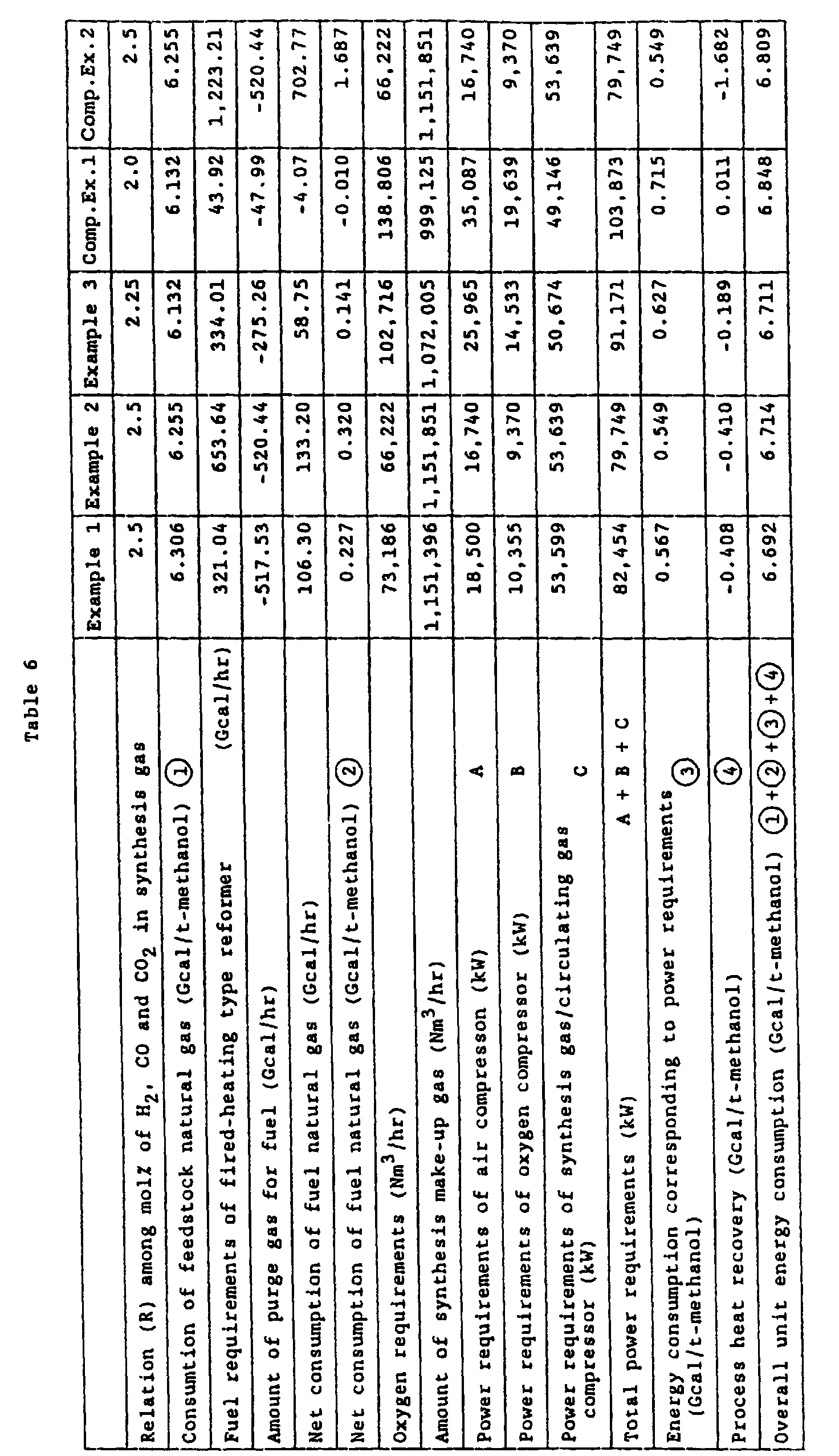
- the energy efficiency of the whole plant was as shown in Table 6, and the overall unit energy consumption (Gcal/ton-methanol) was 6.714.
- the unit energy consumption was improved by 1.40% as compared with Comparative Example 2 of a conventional process. Further, the amount of fuel required for the fired-hearting type reformer and the net consumption of fuel natural gas were reduced in comparison with Comparative Example 2.
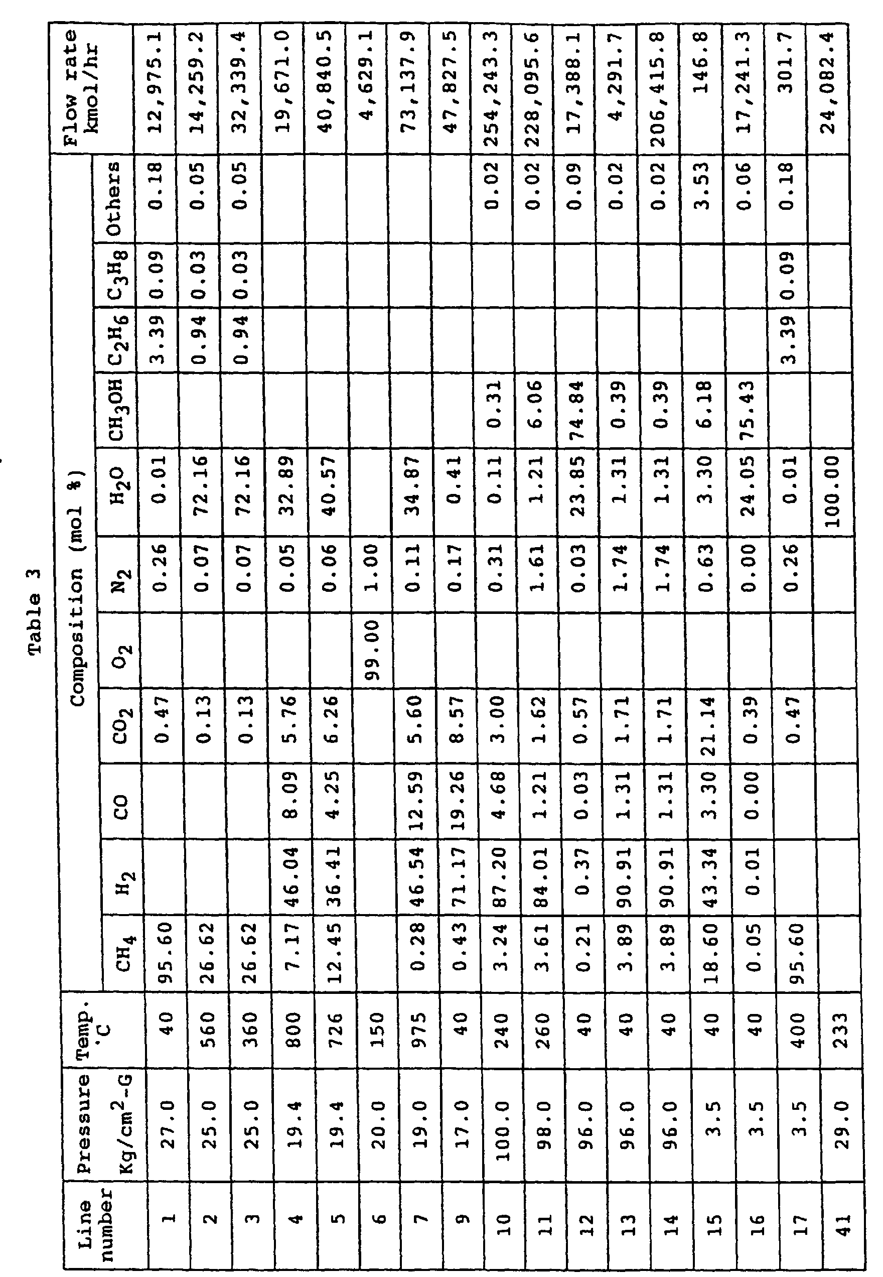
- Example 3 Operation was carried out under the same conditions as in Example 1 except that natural gas of the same composition as used in Example 2 was employed as a feedstock and process design parameters were so regulated that the relation (R) among the mol percentages of CO 2 , Co and H 2 in the synthesis gas may become 2.25.
- the material balance is shown in Table 3.
- the energy efficiency of the whole plant was as shown in Table 6, and the overall unit energy consumption (Gcal/ton-methanol) was 6.711.
- the unit energy consumption was improved by 1.45% as compared with Comparative Example 2 of a conventional process. Further, the amount of fuel required for the fired-heating type reformer and the net consumption of fuel natural gas were reduced in comparison with Comparative Example 2.
- the energy efficiency of the whole plant was as shwon in Table 6, and the overall unit energy consumption (Gcal/ton-methanol) was 6.848.
- the unit energy consumption was degraded by 0.57% as compared with Comparative Example 2 of a conventional process.
- the amount of oxygen required and the total power requirements were increased in comparison with Example 1, Example 2 and Comparative Example 2.
- Example 5 Operation was carried out under the same conditions as in Example 1 except that the primary reforming means was carried out in the conventional manner using only a fired-heating type steam reformer, natural gas of the same composition as used in Example 2 being employed as a feedstock, and process design parameters were so regulated that the relation (R) among the mol percentages of CO 2 , CO and H 2 in the synthesis gas may become 2.5.
- the material balance is shown in Table 5.
- the energy efficiency of the whole plant was as shown in Table 6, and the overall unit energy consumption (Gcal/ton-methanol) was 6.809. In this case, however, the amount of heat recovered from the process exceeds significantly the total power requirements of rotary machines, so that if the excess energy is not sold to the outside, it cannot contribute to the accomplishment of the unit energy consumption described above.
- the energy efficiency of a whole process for the production of methanol including the production of synthesis gas is improved in comparison with the conventional processes and the construction cost of the process plant is also reduced.
Landscapes
- Chemical & Material Sciences (AREA)
- Organic Chemistry (AREA)
- Chemical Kinetics & Catalysis (AREA)
- Health & Medical Sciences (AREA)
- General Health & Medical Sciences (AREA)
- Engineering & Computer Science (AREA)
- Combustion & Propulsion (AREA)
- Inorganic Chemistry (AREA)
- Hydrogen, Water And Hydrids (AREA)
- Organic Low-Molecular-Weight Compounds And Preparation Thereof (AREA)
- Catalysts (AREA)
Abstract
Description

| CH4 | 98.50 mol% |
| C2H6 | 1.00 mol% |
| C3H8 | 0.50 mol% |
| Combustion type steam reforming furnace | 54.4% |
| Heat-exchange type steam reformer | 45.6% |
| Ni | 20 ± 2 wt% |
| Al2O3 | 72 to 75 wt% |
| CaO | < 0.10 wt% |
| TiO2 | < 0.05 wt% |
| SiO2 | < 0.01 wt% |
| Flow rate | 73,186 Nm3/hour |
| Purity | 99.0 % |
| Cr2O3 | 6 ± 2 wt% |
| Al2O3 | 95 to 97 wt% |
| CaO | < 0.10 wt% |
| TiO2 | < 0.05 wt% |
| SiO2 | < 0.10 wt% |
| Ni | 16 ± 1 wt% |
| Al2O3 | 95 to 97 wt% |
| CaO | 0.10 wt% |
| Ti | 3.00 wt% |
| SiO2 | 0.20 wt% |
| CuO | 20 to 50 wt% |
| ZnO | 15 to 60 wt% |
| Al2O3 | 5 to 30 wt% |
| MgO | 0.2 to 7 wt% |
- Temperature of catalyst bed
- 240 to 260°C
| CH4 | 95.60 mol% |
| C2H6 | 3.39 mol% |
| C3H8 | 0.09 mol% |
| C4H10 | 0.03 mol% |
| C5H12 | 0.01 mol% |
| C6H14 | 0.14 mol% |
| N2 | 0.26 mol% |
| CO2 | 0.47 mol% |
| H2O | 0.01 mol% |
| Fired-heating type steam reformer | 58.7% |
| Heat-exchange type steam reformer | 41.3% |

| Fired-heating type steam reformer | 30.6% |
| Heat-exchange type steam reformer | 69.4% |
| Fired-heating type steam reformer | 4.1% |
| Heat-exchange type steam reformer | 95.9% |


Claims (4)
- A process for producing methanol which comprises subjecting a feedstock gas comprising hydrocarbons having atomic ratios H/C of hydrogen (H) to carbon (C) of 3 - 4 or a feedstock gas formed by treating hydrocarbons having atomic ratios H/C of 2 - 3 in a prereformer to primary reforming under the conditions of a pressure of 15 - 40 Kg/cm2-G, a catalyst outlet temperature of 750 - 850°C and a molar ratio S/C of steam (S) to carbon (c) in the feedstck gas of 2.5 - 4.0 and then to secondary reforming using oxygen having a purity of 95% or more under the conditions of a pressure of 15 - 40 Kg/cm2-G and a catalyst outlet temperature of 950 - 1,000°C to obtain a synthesis gas in which the relation (R) among the mol percentages of hydrogen, carbon monoxide and carbon dioxide is 2.2 - 2.5 as calculated according to the following equation
- The process according to Claim 1 wherein said combustion gas is obtained by burning a synthesis gas which has been dissolved in methanol discharged from the methanol synthesis and is evolved by reducing the pressure of the methanol to atmospheric pressure, in addition to the part of the feedstock gas and the synthesis purge gas.
- The process according to Claim 1, wherein an effluent gas comprising methanol and unreacted synthesis gas, the heat content of which was recovered by generating steam and which was discharged from the methanol synthesis, is heat-exchanged with the synthesis gas to be introduced into the methanol synthesis to heat said synthesis gas.
- The process according to Claim 1, wherein the synthesis gas discharged from said secondary reformer and heat-exchanged in said heat-exchange type steam reformer is cooled by exchanging heat with water for generating steam used for the heat recovery in the methanol synthesis.
Applications Claiming Priority (5)
| Application Number | Priority Date | Filing Date | Title |
|---|---|---|---|
| JP36334697 | 1997-11-27 | ||
| JP36334697 | 1997-11-27 | ||
| JP33294198A JP4033988B2 (en) | 1997-11-27 | 1998-11-24 | Method for producing methanol |
| JP33294198 | 1998-11-24 | ||
| PCT/JP1998/005317 WO1999028281A1 (en) | 1997-11-27 | 1998-11-26 | Method of producing methanol |
Publications (3)
| Publication Number | Publication Date |
|---|---|
| EP1016643A1 true EP1016643A1 (en) | 2000-07-05 |
| EP1016643A4 EP1016643A4 (en) | 2004-03-31 |
| EP1016643B1 EP1016643B1 (en) | 2006-10-04 |
Family
ID=26574351
Family Applications (1)
| Application Number | Title | Priority Date | Filing Date |
|---|---|---|---|
| EP98955934A Expired - Lifetime EP1016643B1 (en) | 1997-11-27 | 1998-11-26 | Method of producing methanol |
Country Status (7)
| Country | Link |
|---|---|
| US (1) | US6100303A (en) |
| EP (1) | EP1016643B1 (en) |
| JP (1) | JP4033988B2 (en) |
| BR (1) | BR9806130A (en) |
| DE (1) | DE69836091T2 (en) |
| DK (1) | DK1016643T3 (en) |
| WO (1) | WO1999028281A1 (en) |
Cited By (16)
| Publication number | Priority date | Publication date | Assignee | Title |
|---|---|---|---|---|
| EP1985580A1 (en) * | 2007-04-27 | 2008-10-29 | Methanol Casale S.A. | Process for producing methanol synthesis gas |
| WO2011009437A2 (en) | 2009-07-23 | 2011-01-27 | Lurgi Gmbh | Method and plant for the production of methanol |
| DE102011017300A1 (en) | 2011-04-15 | 2012-10-18 | Lurgi Gmbh | Process and plant for the production of methanol from inert synthesis gas |
| CN104583121A (en) * | 2012-09-12 | 2015-04-29 | 三菱重工业株式会社 | Reforming device, reforming method, manufacturing device of chemical product having reforming device, and manufacturing method of chemical product |
| DE102016100909A1 (en) | 2015-12-18 | 2017-06-22 | L'Air Liquide, Société Anonyme pour l'Etude et l'Exploitation des Procédés Georges Claude | Washing device for separating methanol from gases |
| DE102016100911A1 (en) | 2015-12-18 | 2017-06-22 | L'Air Liquide, Société Anonyme pour l'Etude et l'Exploitation des Procédés Georges Claude | Method and apparatus for recovering methanol |
| EP3219697A1 (en) | 2016-03-16 | 2017-09-20 | L'Air Liquide Société Anonyme pour l'Etude et l'Exploitation des Procédés Georges Claude | The synthesis of methanol from synthesis gases with hydrogen mangle |
| US10093541B2 (en) | 2014-02-28 | 2018-10-09 | Haldor Topsoe A/S | Process for producing synthesis gas |
| EP3401299A1 (en) | 2017-05-12 | 2018-11-14 | L'air Liquide, Société Anonyme Pour L'Étude Et L'exploitation Des Procédés Georges Claude | Reactor for carrying out exothermic equilibrium reactions |
| EP3401300A1 (en) | 2017-05-12 | 2018-11-14 | L'air Liquide, Société Anonyme Pour L'Étude Et L'exploitation Des Procédés Georges Claude | Method for carrying out exothermic equilibrium reactions |
| WO2019220074A1 (en) * | 2018-05-14 | 2019-11-21 | Johnson Matthey Public Limited Company | Process |
| EP3808724A1 (en) | 2019-10-16 | 2021-04-21 | L'air Liquide, Société Anonyme Pour L'Étude Et L'exploitation Des Procédés Georges Claude | Method for producing methanol by multi-stage synthesis |
| EP3808725A1 (en) | 2019-10-16 | 2021-04-21 | L'air Liquide, Société Anonyme Pour L'Étude Et L'exploitation Des Procédés Georges Claude | Method for the multi-stage production of methanol |
| EP3885335A1 (en) | 2020-03-26 | 2021-09-29 | L'air Liquide, Société Anonyme Pour L'Étude Et L'exploitation Des Procédés Georges Claude | Method and system for producing pure hydrogen |
| EP4015496A1 (en) | 2020-12-15 | 2022-06-22 | L'Air Liquide - Société Anonyme pour l'Etude et l'Exploitation des Procédés Georges Claude | Method and installation for producing methanol from under-stoichiometric synthesis gas |
| EP4480575A1 (en) | 2023-06-23 | 2024-12-25 | L'air Liquide, Societe Anonyme Pour L'etude Et L'exploitation Des Procedes Georges Claude | Cooled reactor for carrying out exothermic equilibrium reactions |
Families Citing this family (19)
| Publication number | Priority date | Publication date | Assignee | Title |
|---|---|---|---|---|
| JP4959074B2 (en) * | 2001-07-19 | 2012-06-20 | 三菱重工業株式会社 | Method for producing methanol |
| US7151198B2 (en) * | 2002-12-30 | 2006-12-19 | Exxonmobil Chemical Patents Inc. | Integration of a methanol synthesis system with a methanol to olefin reaction system |
| US7161051B2 (en) * | 2002-12-30 | 2007-01-09 | Exxonmobil Chemical Patents Inc. | Integration of a methanol synthesis system with a methanol to olefin reaction system |
| DK2142467T4 (en) * | 2007-04-04 | 2015-03-23 | Saudi Basic Ind Corp | PROCEDURE FOR COMBINED reforming FOR METHANOL PRODUCTION |
| KR101068995B1 (en) | 2008-12-08 | 2011-09-30 | 현대중공업 주식회사 | Synthesis method of methanol using syngas produced by mixing and reforming methane, steam and carbon dioxide |
| US8033663B2 (en) * | 2009-02-17 | 2011-10-11 | Essilor International (Compagnie Generale D'optique) | Abrasion-resistant tintable coating |
| DK2464598T3 (en) | 2009-08-14 | 2013-10-28 | Saudi Basic Ind Corp | Combined reforming process for methanol production |
| JP5863979B2 (en) * | 2012-09-12 | 2016-02-17 | 三菱重工業株式会社 | Reforming apparatus and reforming method, chemical product manufacturing apparatus equipped with reforming apparatus, and chemical product manufacturing method |
| KR101790102B1 (en) * | 2014-08-04 | 2017-10-25 | 한국화학연구원 | Highly efficient methanol production method with low carbon dioxide emission |
| CN104387230B (en) * | 2014-11-21 | 2016-02-10 | 中煤能源黑龙江煤化工有限公司 | A kind of method using the device process methyl alcohol flash steam of process methyl alcohol flash steam |
| CN111433549A (en) | 2017-07-17 | 2020-07-17 | 分形散热器技术有限责任公司 | Multi-fractal heat sink system and method |
| KR102787291B1 (en) | 2019-01-15 | 2025-03-27 | 사빅 글로벌 테크놀러지스 비.브이. | Use of intermittent energy in the production of chemicals |
| WO2020174059A1 (en) * | 2019-02-28 | 2020-09-03 | Haldor Topsøe A/S | Parallel reforming in chemical plant |
| US12398035B2 (en) | 2019-02-28 | 2025-08-26 | Haldor Topsøe A/S | Synthesis gas production by steam methane reforming |
| CN112194566A (en) * | 2020-09-29 | 2021-01-08 | 浙江工业大学 | Device and process for synthesizing methanol based on carbon dioxide hydrogenation |
| EP4015450A1 (en) * | 2020-12-15 | 2022-06-22 | Haldor Topsøe A/S | Hydrocarbon upgrading to methanol and hydrogen product streams |
| EP4105170A1 (en) | 2021-06-18 | 2022-12-21 | Technip Energies France | Process and plant for flexible production of syngas from hydrocarbons |
| WO2023012837A1 (en) * | 2021-08-04 | 2023-02-09 | NextChem S.p.A. | Apparatus for hydrogen production |
| KR20230108605A (en) * | 2022-01-11 | 2023-07-18 | 현대자동차주식회사 | Fuel reforming device |
Family Cites Families (6)
| Publication number | Priority date | Publication date | Assignee | Title |
|---|---|---|---|---|
| NL8103397A (en) * | 1981-07-17 | 1983-02-16 | Shell Int Research | METHOD FOR PREPARING ORGANIC COMPOUNDS. |
| GB8520567D0 (en) * | 1985-08-16 | 1985-09-25 | British Petroleum Co Plc | Production of synthesis gas |
| JP2984720B2 (en) * | 1991-06-10 | 1999-11-29 | 千代田化工建設株式会社 | Methanol synthesis process and plant |
| JPH07126201A (en) * | 1993-10-27 | 1995-05-16 | Mitsubishi Gas Chem Co Inc | Methanol production process |
| RU2174942C2 (en) * | 1995-11-23 | 2001-10-20 | Метанол Касэл С.А. | Combined ammonia-methanol production process |
| JPH10259148A (en) * | 1997-03-19 | 1998-09-29 | Mitsubishi Heavy Ind Ltd | Production of methanol from synthesis gas |
-
1998
- 1998-11-24 JP JP33294198A patent/JP4033988B2/en not_active Expired - Fee Related
- 1998-11-26 BR BR9806130-5A patent/BR9806130A/en not_active IP Right Cessation
- 1998-11-26 EP EP98955934A patent/EP1016643B1/en not_active Expired - Lifetime
- 1998-11-26 DE DE69836091T patent/DE69836091T2/en not_active Expired - Lifetime
- 1998-11-26 WO PCT/JP1998/005317 patent/WO1999028281A1/en not_active Ceased
- 1998-11-26 US US09/341,693 patent/US6100303A/en not_active Expired - Lifetime
- 1998-11-26 DK DK98955934T patent/DK1016643T3/en active
Cited By (40)
| Publication number | Priority date | Publication date | Assignee | Title |
|---|---|---|---|---|
| WO2008131847A1 (en) * | 2007-04-27 | 2008-11-06 | Methanol Casale S.A. | Process for producing methanol synthesis gas |
| EP1985580A1 (en) * | 2007-04-27 | 2008-10-29 | Methanol Casale S.A. | Process for producing methanol synthesis gas |
| US9040594B2 (en) | 2009-07-23 | 2015-05-26 | Air Liquide Global E&C Solutions Germany Gmbh | Method and plant for the production of methanol |
| WO2011009437A2 (en) | 2009-07-23 | 2011-01-27 | Lurgi Gmbh | Method and plant for the production of methanol |
| DE102009034551A1 (en) | 2009-07-23 | 2011-02-03 | Lurgi Gmbh | Process and plant for the production of methanol |
| EP2281793A1 (en) | 2009-07-23 | 2011-02-09 | Lurgi GmbH | Method and device for manufacturing methanol |
| WO2012139703A1 (en) | 2011-04-15 | 2012-10-18 | Lurgi Gmbh | Method and system for producing methanol from inert-rich syngas |
| US9296672B2 (en) | 2011-04-15 | 2016-03-29 | Air Liquide Global E&C Solutions Germany Gmbh | Process and plant for the production of methanol from synthesis gas rich in inerts |
| DE102011017300A1 (en) | 2011-04-15 | 2012-10-18 | Lurgi Gmbh | Process and plant for the production of methanol from inert synthesis gas |
| US9701600B2 (en) | 2011-04-15 | 2017-07-11 | Air Liquide Glogal E&C Solutions Germany Gmbh | Plant for the production of methanol from synthesis gas rich in inerts |
| CN104583121A (en) * | 2012-09-12 | 2015-04-29 | 三菱重工业株式会社 | Reforming device, reforming method, manufacturing device of chemical product having reforming device, and manufacturing method of chemical product |
| CN104583121B (en) * | 2012-09-12 | 2016-10-12 | 三菱重工业株式会社 | Reforming device, reforming method, manufacturing device of chemical product having reforming device, and manufacturing method of chemical product |
| US10258960B2 (en) | 2012-09-12 | 2019-04-16 | Mitsubishi Heavy Industries Engineering, Ltd. | Reforming device and method for manufacturing chemical products |
| US9737868B2 (en) | 2012-09-12 | 2017-08-22 | Mitsubishi Heavy Industries, Ltd. | Reforming device and reforming method, and device for manufacturing chemical products equipped with reforming device and method for manufacturing chemical products |
| US10093541B2 (en) | 2014-02-28 | 2018-10-09 | Haldor Topsoe A/S | Process for producing synthesis gas |
| DE102016100911A1 (en) | 2015-12-18 | 2017-06-22 | L'Air Liquide, Société Anonyme pour l'Etude et l'Exploitation des Procédés Georges Claude | Method and apparatus for recovering methanol |
| DE102016100909A1 (en) | 2015-12-18 | 2017-06-22 | L'Air Liquide, Société Anonyme pour l'Etude et l'Exploitation des Procédés Georges Claude | Washing device for separating methanol from gases |
| US10843125B2 (en) | 2015-12-18 | 2020-11-24 | L'air Liquide Societe Anonyme Pour L'etude Et L'exploitation Des Procedes Georges Claude | Process for the separation of methanol from gas mixtures |
| WO2017157530A1 (en) | 2016-03-16 | 2017-09-21 | L'AIR LIQUIDE Société Anonyme pour l'Etude et l' Exploitation des Procédés Georges Claude | Methanol synthesis from synthesis gases with hydrogen deficiency |
| DE102016107457A1 (en) | 2016-03-16 | 2017-09-21 | L'Air Liquide, Société Anonyme pour l'Etude et l'Exploitation des Procédés Georges Claude | Methanol synthesis from hydrogen-deficient synthesis gases |
| CN107200679A (en) * | 2016-03-16 | 2017-09-26 | 乔治·克劳德方法的研究开发空气股份有限公司 | Methanol-fueled CLC is carried out by the synthesis gas for lacking hydrogen |
| EP3219697A1 (en) | 2016-03-16 | 2017-09-20 | L'Air Liquide Société Anonyme pour l'Etude et l'Exploitation des Procédés Georges Claude | The synthesis of methanol from synthesis gases with hydrogen mangle |
| CN107200679B (en) * | 2016-03-16 | 2022-02-18 | 乔治·克劳德方法的研究开发空气股份有限公司 | Methanol synthesis from hydrogen deficient synthesis gas |
| US10364202B2 (en) | 2016-03-16 | 2019-07-30 | L'air Liquide Societe Anonyme Pour L'etude Et L'exploitation Des Procedes Georges Claude | Methanol synthesis from synthesis gases with hydrogen deficiency |
| EP3401299A1 (en) | 2017-05-12 | 2018-11-14 | L'air Liquide, Société Anonyme Pour L'Étude Et L'exploitation Des Procédés Georges Claude | Reactor for carrying out exothermic equilibrium reactions |
| WO2018206153A1 (en) | 2017-05-12 | 2018-11-15 | L'air Liquide, Société Anonyme Pour L' Etude Et I' Exploitation Des Procédés Georges Claude | Reactor for conducting exothermic equilibrium reactions |
| WO2018206155A1 (en) | 2017-05-12 | 2018-11-15 | L'Air Liquide, Société Anonyme pour l'Etude et l'Exploitation des Procédés Georges Claude | Process for conducting exothermic equilibrium reactions |
| US10898874B2 (en) | 2017-05-12 | 2021-01-26 | L'air Liquide Societe Anonyme Pour L'etude Et L'exploitation Des Procedes Georges Claude | Reactor for conducting exothermic equilibrium reactions |
| US10913698B2 (en) | 2017-05-12 | 2021-02-09 | L'air Liquide Societe Anonyme Pour L'etude Et L'exploitation Des Procedes Georges Claude | Process for conducting exothermic equilibrium reactions |
| EP3401300A1 (en) | 2017-05-12 | 2018-11-14 | L'air Liquide, Société Anonyme Pour L'Étude Et L'exploitation Des Procédés Georges Claude | Method for carrying out exothermic equilibrium reactions |
| WO2019220074A1 (en) * | 2018-05-14 | 2019-11-21 | Johnson Matthey Public Limited Company | Process |
| EP3808725A1 (en) | 2019-10-16 | 2021-04-21 | L'air Liquide, Société Anonyme Pour L'Étude Et L'exploitation Des Procédés Georges Claude | Method for the multi-stage production of methanol |
| US11247954B2 (en) | 2019-10-16 | 2022-02-15 | L'Air Liquide, Société Anonyme pour l'Etude et l'Exploitation des Procédés Georges Claude | Process for the multistage production of methanol |
| US11247957B2 (en) | 2019-10-16 | 2022-02-15 | L'Air Liquide, Société Anonyme pour l'Etude et l'Exploitation des Procédés Georges Claude | Process for producing methanol by multistage synthesis |
| EP3808724A1 (en) | 2019-10-16 | 2021-04-21 | L'air Liquide, Société Anonyme Pour L'Étude Et L'exploitation Des Procédés Georges Claude | Method for producing methanol by multi-stage synthesis |
| EP3885335A1 (en) | 2020-03-26 | 2021-09-29 | L'air Liquide, Société Anonyme Pour L'Étude Et L'exploitation Des Procédés Georges Claude | Method and system for producing pure hydrogen |
| US11512033B2 (en) | 2020-03-26 | 2022-11-29 | L'Air Liquide, Société Anonyme pour l'Etude et l'Exploitation des Procédés Georges Claude | Process and plant for producing pure methanol |
| EP4015496A1 (en) | 2020-12-15 | 2022-06-22 | L'Air Liquide - Société Anonyme pour l'Etude et l'Exploitation des Procédés Georges Claude | Method and installation for producing methanol from under-stoichiometric synthesis gas |
| US11629111B2 (en) | 2020-12-15 | 2023-04-18 | L'Air Liquide, Société Anonyme pour l'Etude et l'Exploitation des Procédés Georges Claude | Process and plant for producing methanol from substoichiometric synthesis gas |
| EP4480575A1 (en) | 2023-06-23 | 2024-12-25 | L'air Liquide, Societe Anonyme Pour L'etude Et L'exploitation Des Procedes Georges Claude | Cooled reactor for carrying out exothermic equilibrium reactions |
Also Published As
| Publication number | Publication date |
|---|---|
| EP1016643B1 (en) | 2006-10-04 |
| EP1016643A4 (en) | 2004-03-31 |
| DK1016643T3 (en) | 2007-02-05 |
| DE69836091D1 (en) | 2006-11-16 |
| JP4033988B2 (en) | 2008-01-16 |
| DE69836091T2 (en) | 2007-05-03 |
| BR9806130A (en) | 1999-10-26 |
| JPH11263740A (en) | 1999-09-28 |
| US6100303A (en) | 2000-08-08 |
| WO1999028281A1 (en) | 1999-06-10 |
Similar Documents
| Publication | Publication Date | Title |
|---|---|---|
| US6100303A (en) | Method of producing methanol | |
| US12466730B2 (en) | ATR-based hydrogen process and plant | |
| EP3983365B1 (en) | Process for synthesising methanol | |
| EP2142467B1 (en) | Combined reforming process for methanol production | |
| EP0522744B1 (en) | Synthesis gas production | |
| EP2464598B1 (en) | Combined reforming process for methanol production | |
| US20070264186A1 (en) | Process for Production of Hydrogen and/or Carbon Monoxide | |
| CN105820036B (en) | Method and system for producing methanol using partial oxidation | |
| US20250162966A1 (en) | Process for synthesising methanol | |
| EP3983366B1 (en) | Process for synthesising methanol | |
| EP4385947A1 (en) | Decarbonisation of a chemical plant | |
| JP3947266B2 (en) | Hydrogen production method and apparatus used therefor | |
| WO2025120130A1 (en) | Low carbon intensity methanol production | |
| EP1985580A1 (en) | Process for producing methanol synthesis gas |
Legal Events
| Date | Code | Title | Description |
|---|---|---|---|
| PUAI | Public reference made under article 153(3) epc to a published international application that has entered the european phase |
Free format text: ORIGINAL CODE: 0009012 |
|
| 17P | Request for examination filed |
Effective date: 19990519 |
|
| AK | Designated contracting states |
Kind code of ref document: A1 Designated state(s): DE DK GB |
|
| A4 | Supplementary search report drawn up and despatched |
Effective date: 20040217 |
|
| RIC1 | Information provided on ipc code assigned before grant |
Ipc: 7C 01B 3/38 B Ipc: 7C 07C 29/151 A |
|
| GRAP | Despatch of communication of intention to grant a patent |
Free format text: ORIGINAL CODE: EPIDOSNIGR1 |
|
| RAP1 | Party data changed (applicant data changed or rights of an application transferred) |
Owner name: TOYO ENGINEERING CORPORATION |
|
| GRAS | Grant fee paid |
Free format text: ORIGINAL CODE: EPIDOSNIGR3 |
|
| GRAA | (expected) grant |
Free format text: ORIGINAL CODE: 0009210 |
|
| AK | Designated contracting states |
Kind code of ref document: B1 Designated state(s): DE DK GB |
|
| REG | Reference to a national code |
Ref country code: GB Ref legal event code: FG4D |
|
| REF | Corresponds to: |
Ref document number: 69836091 Country of ref document: DE Date of ref document: 20061116 Kind code of ref document: P |
|
| REG | Reference to a national code |
Ref country code: DK Ref legal event code: T3 |
|
| PLBE | No opposition filed within time limit |
Free format text: ORIGINAL CODE: 0009261 |
|
| STAA | Information on the status of an ep patent application or granted ep patent |
Free format text: STATUS: NO OPPOSITION FILED WITHIN TIME LIMIT |
|
| 26N | No opposition filed |
Effective date: 20070705 |
|
| PGFP | Annual fee paid to national office [announced via postgrant information from national office to epo] |
Ref country code: DE Payment date: 20161123 Year of fee payment: 19 Ref country code: GB Payment date: 20161123 Year of fee payment: 19 Ref country code: DK Payment date: 20161110 Year of fee payment: 19 |
|
| REG | Reference to a national code |
Ref country code: DE Ref legal event code: R119 Ref document number: 69836091 Country of ref document: DE |
|
| REG | Reference to a national code |
Ref country code: DK Ref legal event code: EBP Effective date: 20171130 |
|
| GBPC | Gb: european patent ceased through non-payment of renewal fee |
Effective date: 20171126 |
|
| PG25 | Lapsed in a contracting state [announced via postgrant information from national office to epo] |
Ref country code: DE Free format text: LAPSE BECAUSE OF NON-PAYMENT OF DUE FEES Effective date: 20180602 |
|
| PG25 | Lapsed in a contracting state [announced via postgrant information from national office to epo] |
Ref country code: DK Free format text: LAPSE BECAUSE OF NON-PAYMENT OF DUE FEES Effective date: 20171130 Ref country code: GB Free format text: LAPSE BECAUSE OF NON-PAYMENT OF DUE FEES Effective date: 20171126 |