EP1015947B1 - Verfahren und vorrichtung zur durchlaufbearbeitung von plattenförmigen werkstücken - Google Patents
Verfahren und vorrichtung zur durchlaufbearbeitung von plattenförmigen werkstücken Download PDFInfo
- Publication number
- EP1015947B1 EP1015947B1 EP98948970A EP98948970A EP1015947B1 EP 1015947 B1 EP1015947 B1 EP 1015947B1 EP 98948970 A EP98948970 A EP 98948970A EP 98948970 A EP98948970 A EP 98948970A EP 1015947 B1 EP1015947 B1 EP 1015947B1
- Authority
- EP
- European Patent Office
- Prior art keywords
- fine
- workpiece
- work piece
- sensor
- control device
- Prior art date
- Legal status (The legal status is an assumption and is not a legal conclusion. Google has not performed a legal analysis and makes no representation as to the accuracy of the status listed.)
- Expired - Lifetime
Links
Images


Classifications
-
- B—PERFORMING OPERATIONS; TRANSPORTING
- B27—WORKING OR PRESERVING WOOD OR SIMILAR MATERIAL; NAILING OR STAPLING MACHINES IN GENERAL
- B27D—WORKING VENEER OR PLYWOOD
- B27D5/00—Other working of veneer or plywood specially adapted to veneer or plywood
- B27D5/003—Other working of veneer or plywood specially adapted to veneer or plywood securing a veneer strip to a panel edge
-
- B—PERFORMING OPERATIONS; TRANSPORTING
- B27—WORKING OR PRESERVING WOOD OR SIMILAR MATERIAL; NAILING OR STAPLING MACHINES IN GENERAL
- B27M—WORKING OF WOOD NOT PROVIDED FOR IN SUBCLASSES B27B - B27L; MANUFACTURE OF SPECIFIC WOODEN ARTICLES
- B27M1/00—Working of wood not provided for in subclasses B27B - B27L, e.g. by stretching
- B27M1/08—Working of wood not provided for in subclasses B27B - B27L, e.g. by stretching by multi-step processes
-
- G—PHYSICS
- G05—CONTROLLING; REGULATING
- G05B—CONTROL OR REGULATING SYSTEMS IN GENERAL; FUNCTIONAL ELEMENTS OF SUCH SYSTEMS; MONITORING OR TESTING ARRANGEMENTS FOR SUCH SYSTEMS OR ELEMENTS
- G05B19/00—Program-control systems
- G05B19/02—Program-control systems electric
- G05B19/18—Numerical control [NC], i.e. automatically operating machines, in particular machine tools, e.g. in a manufacturing environment, so as to execute positioning, movement or co-ordinated operations by means of program data in numerical form
- G05B19/19—Numerical control [NC], i.e. automatically operating machines, in particular machine tools, e.g. in a manufacturing environment, so as to execute positioning, movement or co-ordinated operations by means of program data in numerical form characterised by positioning or contouring control systems, e.g. to control position from one programmed point to another or to control movement along a programmed continuous path
- G05B19/39—Numerical control [NC], i.e. automatically operating machines, in particular machine tools, e.g. in a manufacturing environment, so as to execute positioning, movement or co-ordinated operations by means of program data in numerical form characterised by positioning or contouring control systems, e.g. to control position from one programmed point to another or to control movement along a programmed continuous path using a combination of the means covered by at least two of the preceding groups G05B19/21, G05B19/27 and G05B19/33
-
- G—PHYSICS
- G05—CONTROLLING; REGULATING
- G05B—CONTROL OR REGULATING SYSTEMS IN GENERAL; FUNCTIONAL ELEMENTS OF SUCH SYSTEMS; MONITORING OR TESTING ARRANGEMENTS FOR SUCH SYSTEMS OR ELEMENTS
- G05B19/00—Program-control systems
- G05B19/02—Program-control systems electric
- G05B19/418—Total factory control, i.e. centrally controlling a plurality of machines, e.g. direct or distributed numerical control [DNC], flexible manufacturing systems [FMS], integrated manufacturing systems [IMS] or computer integrated manufacturing [CIM]
- G05B19/41815—Total factory control, i.e. centrally controlling a plurality of machines, e.g. direct or distributed numerical control [DNC], flexible manufacturing systems [FMS], integrated manufacturing systems [IMS] or computer integrated manufacturing [CIM] characterised by the cooperation between machine tools, manipulators and conveyor or other workpiece supply system, workcell
-
- G—PHYSICS
- G05—CONTROLLING; REGULATING
- G05B—CONTROL OR REGULATING SYSTEMS IN GENERAL; FUNCTIONAL ELEMENTS OF SUCH SYSTEMS; MONITORING OR TESTING ARRANGEMENTS FOR SUCH SYSTEMS OR ELEMENTS
- G05B2219/00—Program-control systems
- G05B2219/30—Nc systems
- G05B2219/41—Servomotor, servo controller till figures
- G05B2219/41106—Coarse fine take over, transition, switch over
-
- G—PHYSICS
- G05—CONTROLLING; REGULATING
- G05B—CONTROL OR REGULATING SYSTEMS IN GENERAL; FUNCTIONAL ELEMENTS OF SUCH SYSTEMS; MONITORING OR TESTING ARRANGEMENTS FOR SUCH SYSTEMS OR ELEMENTS
- G05B2219/00—Program-control systems
- G05B2219/30—Nc systems
- G05B2219/45—Nc applications
- G05B2219/45054—Handling, conveyor
-
- G—PHYSICS
- G05—CONTROLLING; REGULATING
- G05B—CONTROL OR REGULATING SYSTEMS IN GENERAL; FUNCTIONAL ELEMENTS OF SUCH SYSTEMS; MONITORING OR TESTING ARRANGEMENTS FOR SUCH SYSTEMS OR ELEMENTS
- G05B2219/00—Program-control systems
- G05B2219/30—Nc systems
- G05B2219/50—Machine tool, machine tool null till machine tool work handling
- G05B2219/50216—Synchronize speed and position of several axis, spindles
-
- Y—GENERAL TAGGING OF NEW TECHNOLOGICAL DEVELOPMENTS; GENERAL TAGGING OF CROSS-SECTIONAL TECHNOLOGIES SPANNING OVER SEVERAL SECTIONS OF THE IPC; TECHNICAL SUBJECTS COVERED BY FORMER USPC CROSS-REFERENCE ART COLLECTIONS [XRACs] AND DIGESTS
- Y02—TECHNOLOGIES OR APPLICATIONS FOR MITIGATION OR ADAPTATION AGAINST CLIMATE CHANGE
- Y02P—CLIMATE CHANGE MITIGATION TECHNOLOGIES IN THE PRODUCTION OR PROCESSING OF GOODS
- Y02P90/00—Enabling technologies with a potential contribution to greenhouse gas [GHG] emissions mitigation
- Y02P90/02—Total factory control, e.g. smart factories, flexible manufacturing systems [FMS] or integrated manufacturing systems [IMS]
Definitions
- the present invention relates to a method for Processing of plate-shaped workpieces made of wood, Wood materials, plastic or the like, in which the Workpieces are gripped continuously along a Processing line guided and with at least one means along the processing line for Machining can be engaged.
- the present invention further relates to a device for processing plate-shaped materials made of wood, wood-based materials, Plastic or the like with a conveyor for Detect and continuously guide the workpieces along a processing line and at least one in the area the conveyor arranged processing unit with at least one means which is used to process a Workpiece can be brought into engagement with this.
- Processes of this type are commonly referred to as continuous processes and devices for performing this method in general referred to as continuous machines. They are suitable for Continuous processing of inherently rigid plate material, such as e.g. Solid wood or chipboard, so-called blockboard, Plywood panels, composite panels made of wood, plastic and Metal or the like.
- inherently rigid plate material such as e.g. Solid wood or chipboard, so-called blockboard, Plywood panels, composite panels made of wood, plastic and Metal or the like.
- the generated by the workpiece detection and the measuring system Signals are fed to a central control unit which these signals processed and depending on each desired processing according to predetermined programs Processing devices or processing units and thus controls the means for machining the workpieces.
- the central control unit In the inlet area of the conveyor at the beginning of the Feed transport is the central control unit Signal supplied via the workpiece detection.
- the Control unit now calculates that from the position measuring system output feed taking into account the Feed speed to determine the movement of the agent Carrying out an intervention taking into account the Feed speed of the workpiece with a defined one Start to start.
- the object of the present invention is a method and a device for processing plate-shaped Workpieces made of wood in the pass specify it enable the precision of the machining of the workpiece increase without the throughput speed of the Workpiece must be reduced.
- the method of the present invention for machining of plate-shaped workpieces made of wood, wooden workpieces, Plastic or the like, in which the workpieces are gripped, continuously guided along a processing line, and with at least one along the processing line managed means are brought into processing, provides that for the relative positioning of the with the respective workpiece to be engaged in a first phase via a first control device Compared to the respective workpiece in a predetermined Tolerance zone regarding relative movement and position to be led. After reaching the tolerance zone, the Movement of the agent one of an additional Control device controlled fine movement up to one Fine positioning of the agent overlaid. After The procedure is carried out with fine positioning.
- An inventive device for performing a The inventive method comprises a conveyor for Detection and guidance of a workpiece along the Processing line, and at least one in the range of Conveying device arranged processing unit with a or several means for machining the workpieces.
- a first control device is used to guide the agent into the specified tolerance zone in order to machine the workpieces.
- An additional control device is for superimposing one Fine movement to that of the first control device controlled movement provided to fine the agent position.
- “Overlay” is understood to mean a measure with which a basic movement another movement with positive or negative sign is added, so that a resulting movement results in larger within certain limits or can be smaller than the basic movement.
- superposition can be based on mechanical, pneumatic, electrical or electronic way.
- Such an "overlay" can be mechanically for example over two arranged on top of each other Carriage arrangements can be realized, one of which (lower) carriage arrangement the basic movement and the other (Upper) carriage arrangement which carries out further movement, see above that the moving part of the other (upper) Carriage assembly performs the resulting movement.
- the mechanical variant of the "overlay" can also can be achieved via a gear arrangement in which one first transmission element performing the basic movement connected, further gear links a further movement is added up, so that the output branch of the first Transmission link in such a phase the resulting Movement.
- the "overlay” will be for example, control signals added or subtracted and that Result of the overlay converted into a movement.
- overlay also includes the numerical one Linking tax data and the implementation of the linked Control data in one motion, such as the overlay or switching of control loops to achieve the Basic movement and fine movement.
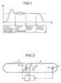
- Figure 1 shows a speed path diagram for explanation a continuous machining process according to the present Invention.
- the diagram s plots the path s over which the Velocity V of engages with the workpiece stepping agent is shown.
- the horizontal, dashed line indicates the speed of the workpiece on.
- the speed of the workpiece over the distance traveled Way a size to which the speed of with the Adjusted workpiece to be engaged means so is that a precise machining of the workpiece is achieved becomes.
- the speed of the Workpiece adapted to the speed of the agent become, without this a substantial deviation from the would represent the principle underlying the invention.
- a such a predetermined tolerance zone can be approximately one Speed interval of the speed of the agent be relative to the workpiece, or a position interval of Position of the agent relative to a given one Reference position of the workpiece, or preferably both.
- the agent can be guided into the tolerance zone thus specified done in a conventional manner, such as using the of the position measuring system for the workpiece feed provided signals and signals that a path encoder of the agent.
- the second phase a fine positioning of the agent in relation to the machining workpiece performed.
- the agent is managed in the tolerance zone and also the position of the agent relative to the workpiece recorded with high precision and with a fine position specification of the Compared relative to the workpiece.
- To the The movement of the Layered by means of a fine movement until the mean is relative fulfills the fine position specification for the continuous workpiece.
- the detection of the Fine position of the agent relative to the workpiece with high sensory resolution can be made. It is sufficient that the Fine position sensors cover the specified tolerance zone, in which is the means relative to the workpiece.
- the second phase of the sensory workpiece Extend fine correction into phase 3 of the procedure. Even during the procedure, the process of Fine positioning of the agent relative to the workpiece be continued. This is the case, for example, if the position of the agent relative to the workpiece is not a predetermined point, i.e. a one-dimensional Position specification, but about a trajectory along which the agent is to engage the workpiece, for example to produce a multidimensional contour on the continuous workpiece.
- a fourth phase in which means a retreat back to the starting position carries out the processing of the next, continuous Prepare the workpiece.
- This withdrawal phase can be on conventional way and is not available in direct connection with the present invention, so that this withdrawal phase 4 is only indicated in FIG. Will be the agent to be engaged with the workpiece led circumferentially, so can be shown in Figure 1 Delay of the agent in phase 4 to speed 0 to reverse movement.
- phase 2 Speed profile over the path s and that in phase 2 illustrated undershoot of the speed profile the path s represent exemplary speed paths that are for different relative positions and Relative speeds between the workpiece and the medium at the end of phase 1.
- the results in phase 2 shown overshoot an exaggeration of Speed of the means in comparison to the speed of the workpiece, if at the end of phase 1 the mean is relative to the workpiece is in the tolerance zone, but behind the Fine position specification lagged behind with respect to the workpiece.
- the result shown in phase 2 results accordingly Undershoot if at the end of phase 1 the mean relative to the workpiece in the specified tolerance zone is, however, the fine position specification relative to Workpiece rushes ahead.
- Figure 2 shows an embodiment of a continuous machine according to the present invention.
- the reference symbol B is a conveyor, here for example a conveyor belt or a transport chain for Transporting a workpiece T1 along a Throughput processing path.
- Av denotes a Drive unit of the conveyor B.
- Gv denotes one Displacement sensor, the displacement signals corresponding to that of the Conveyor B outputs the distance traveled.
- SV draws one along the transport path of the workpiece T1 arranged sensor for detecting the workpiece T1.
- A1 denotes a drive unit for a processing unit for continuous processing of the on the conveyor B continuous workpiece T1.
- the drive unit A1 serves to the processing unit one the continuous Corresponding translatory movement to workpiece T1 to lend.
- S1 denotes a displacement sensor for the output of Signals corresponding to that from the processing unit distance traveled.
- A2 denotes a drive unit for a with the workpiece T1 means to be engaged, such as a tool.
- This Drive unit is part of the processing unit.
- S2 denotes a fine position sensor, which on the Processing unit is arranged and designed such that he prefers a fine position of the processing unit of the agent.
- C1 denotes a control unit for the processing unit, the signals output by the sensors Sv, S1, S2 and Gv receives and the drive unit A1 for the Processing unit and the drive unit A2 for the Means, such as the tool, of the processing unit controls according to the received signals.
- the conveyor belt B of the continuous machine left and right of the processing unit on the top and Openwork on the underside to indicate that the Continuous processing machine of Figure 2 a variety of in Direction of passage of the workpiece T1 one after the other arranged processing units can have, respectively with one assigned to the respective unit Control device to work on the workpiece T1 different processing steps in a row perform.
- Each of these processing units can one own sensor Sv for detecting the workpiece T1, one own sensor S1 for detecting the position of the Processing unit and its own sensor S2 for Detection of the fine position of the processing unit relative to workpiece T1, as well as own drive units A1 and A2 include.
- the control devices of each Processing units receive the Gv from the displacement sensor for the conveyor belt B output measuring signals. The following description of the operation of the in Figure 2 shown processing unit applies accordingly accordingly also for others along the direction of flow of the workpiece T1 arranged, not shown in Figure 2 Processing units.
- Continuous machine receives control C1 for that Processing unit from the displacement sensor Gv displacement signals with respect to the conveyor belt B, which is also a determination of the Transport speed of the workpiece T1 through the Allow control device C1.
- Both the identified route as well as the determined speed of the workpiece T1 are, however, with the disturbance variables mentioned at the beginning applied, such as slippage between the conveyor belt B and the workpiece T1 and / or deformations of the conveyor belt B due to the drive unit Av via the belt on the Workpiece T1 transferred feed force.
- the controller C1 prepares for machining the workpiece T1 a tracking movement of the Processing unit before, the sensor S1 of the controller C1 announces the position of the processing unit is currently located. From those provided by the sensor Gv Displacement signals of the conveyor belt B and that of the sensor S1 provided measuring signals of the processing unit can the control C1 in a first phase of the Machining the machining unit relative to that Workpiece T1 to be machined in a specified tolerance zone to lead.
- the control device C1 detects during this first phase whether the workpiece T1 is guided in the specified tolerance zone will or not. Has the processing unit according to the the position signal output to the sensor S1 the position of the Workpiece T1 according to the output from the displacement sensor Gv Position signal within a specified tolerance range reached, and agree from these signals from the Control device C1 determined speeds of the Workpiece T1 and the processing unit within predefined speed tolerance limits, so is the goal pursued with the first phase, the workpiece T1 in Regarding the processing unit in the given Leading tolerance zone reached.
- the sensor Sv takes over Function by the measuring sensor Gv of the conveyor belt B output information about the workpiece T1 distance traveled by detecting the absolute position of the Correct workpiece T1.
- the sensor Sv is in this Embodiment stationary on the machine in Processing area of the associated processing unit arranged, and tells the control device C1 when the Workpiece T1 at the known position of the sensor Sv located.
- the control device C1 corrects that of the Position sensor Gv information output based on the position information from the sensor Sv Workpiece T1, so that the control device C1 in the area of the processing unit controlled by her the position of the Workpiece T1 can detect with increased precision.
- P refers the sensor Sv is located at a location that allows that the control device C1 already under the workpiece T1 Taking into account the information provided by the sensor Sv leads into the specified tolerance zone. This enables the Sensor Sv the reduction in speed and Position tolerance range of the specified tolerance zone, what for the subsequent second phase of the Machining process is advantageous.
- the Control device C1 the position of the sensor S2 Processing unit, preferably the agent, relative to a position on the workpiece T1 at which the engagement to be held. Since the workpiece T1 is already in the Tolerance zone, the agent is close to the Position specification on workpiece T1 on which the engagement to be held.
- the sensor S2 serves the remaining ones Deviations from this position specification with high resolution detect to enable the controller C1 to Movement of the processing unit so a fine movement superimpose that this deviation from the position specification very much becomes small or disappears.
- the senor S2 is preferably a Relative position sensor trained, which together with the Machining unit is moved and mounted on this.
- the control device C1 controls the drive unit A1 depending on the output signals of sensor S2 so that the Movement of the processing unit to guide it in the tolerance zone according to that of sensors Gv and S1 output signals, a fine movement according to that of S2 output signal is superimposed to that in the Tolerance zone remaining deviations of the mean from the Reduce position and disappear as possible to let.
- This overlay preferably takes place within the Control device C1 and by providing a suitable one Drive signal to the drive device A1 of the Processing unit.
- the agent can be relative to Processing unit be designed to be movable, then the control device C1 a relative movement between means and processing unit controls so that the agent Position specification on workpiece T1 according to the signals of the high-resolution fine position sensor S2 fulfilled.
- the processing unit After the intervention, the processing unit performs a suitable retraction movement, either by braking or by a rotating movement to edit the prepare the next workpiece on the conveyor belt B.
- Figure 3 shows a second embodiment of a Continuous machine according to the present invention, in shape a processing unit that is used to apply Edge material is used on a continuous workpiece.
- T1, T2 and T3 denote workpieces that one after the other on the conveyor belt B Processing unit for applying edge material to be led past.
- the Processing unit is Processing unit stationary, and only that with the machining workpiece engaging means, namely the edge material moves with the workpiece.
- the Processing unit according to that shown in Figure 3 Embodiment comprises a drive unit A1 with a Displacement sensor S1 for the feed of on a roll RK rolled edge material, for example Plastic edging strips.
- the processing unit includes also a fine position sensor S2, which is arranged stationary is and indicates when the front edge of the to be applied Edge material passes the sensor S2.
- This also includes Processing unit a main pressure roller R1 and Pinch rollers R2, R3, R4.
- K denotes a on a side edge of the workpiece T1 in the pass applied edge material section.
- Av denotes a Drive unit for the conveyor belt B.
- Gv denotes one Displacement sensor for measuring the feed of the conveyor belt B.
- Sv denotes a stationary sensor for detecting the Position of the workpieces running through.
- the term "Stationary" means that the sensor is relative to one Machine chassis is immovably arranged.
- the processing unit for applying edge material also includes one not shown in Figure 3 Control device, the signals of the displacement sensor Gv, the Material transport path sensor S1 and sensors Sv and S2 receives and the drive unit A1 for the Edge material transport and the drive unit A3 for the Knife Q controls.
- the sensor Sv detects the position of one of them Processing unit of Figure 3 with an edge providing workpiece. According to the function of the sensor Sv in Figure 2, this sensor enables the control device the displacement signals of the sensor Gv for the feed of the Correct conveyor belt B and in this way a improved precision of position and Speed detection of the workpiece to be machined in To achieve the area of the processing unit.
- the Control device that unrolled from the RK roll Edge material into a by means of the drive unit A1 predetermined tolerance zone with respect to the speed of the Edge material feed and / or the position of the leading edge VK of the edging material.
- the control device processes from the position measuring system S1 of the Edge material transport unit A1 provided Wegmeßsignals from which the control device Determine the speed of the edge material feed and this on the speed of the workpiece feed can adjust itself, which results from the position measuring signals of the sensor Gv results.
- the control device regulates the Edge material transport of the edge material such that the Transport speed of the edge material of the Feed speed of the workpiece to be machined within specified tolerance limits.
- Prefers the edge material transport via the aggregate A1 is like this regulated that the position of the leading edge of the edge material on the handling of the transport path of the edging material the transport path of the workpiece within a predetermined Tolerance limits on the position of the leading edge of the machining workpiece corresponds.
- This requirement can Control device from knowledge of the length of the Edge material transport path, the position of the knife Q and that of the edging material transport unit A1 Edge material feed according to that of the associated one Displacement sensor S1 meet the displacement signals output.
- the leading edge of the edge material to be applied this Position specification within the specified tolerance limits fulfilled the first processing phase is complete and that Edge material is guided in the specified tolerance zone.
- the leading edge VK of the Edge material then passes the fine position sensor S2.
- the Fine position sensor S2 is a in this embodiment stationary sensor, that of the control device tells at what time the leading edge VK the Detection position of sensor S2 reached. From this of that Sensor S2 is the information provided Control device now able to calculate how much the position of the leading edge VK on the development of the Transport path of the edge material from the position of the The front edge of the workpiece to be machined deviates. Corresponding to the fine position deviation of the Front edge VK of the edge material from the front edge of the The workpiece is then the control device Drive unit A1 for the edge material transport so controlled that this fine position deviation is reduced and disappears if possible. To do this, the feed movement of the Edge material a fine feed movement of the Control device superimposed to this fine position deviation compensate.
- leading edge VK of the edge material at a position on the Processing of the edge material transport path on the path of Leading edge of the workpiece with good precision of the Corresponds to the leading edge position of the workpiece, so that at the Place where the edge material transport path is on the transport path of the workpiece hits the leading edge VK of the edge material precisely on the front edge of the workpiece meets.
- the side length of the to be processed Workpiece corresponds to that via the drive unit A3 Knife Q operated to the appropriate length of edging material cut off what the process of applying Edge material in the run ends.
- Fig. 4 shows a third embodiment of a Continuous machine according to the present invention, in shape a processing unit, which for the so-called “capping" of in a previous step on the respective Serves applied edge material and therefore is commonly referred to as a trimming unit.
- a trimming unit is considered (viewed in the direction of flow) the over the workpiece leading edge and / or the Precise edge section protruding from the workpiece flush to the workpiece front edge or to the workpiece rear edge separated.
- the application of the edging material in the previous Operation can be done using conventional edge banding units, however, preferably via the processing unit according to FIG. 3 the protruding edge part extremely due to the precise operation of this unit can be kept small.
- T1, T2 and T3 denote workpieces that one after the other on the conveyor belt B on the cross-cutting unit to be led past.
- the trimming unit includes a so-called straight guide F1, the next to the conveyor belt and runs parallel to it.
- the Straight guide F1 comprises two spaced apart and parallel to each other extending guide rods f1 and f2, on which one Base plate G in the direction of an arrow P1, that is parallel to Conveyor belt, is slidably back and forth.
- a rack Z is attached, which with the pinion (not shown) of a stationary arrangement
- Drive motor M is connected to a position measuring system Kappaggregates works together.
- the reference character Av a drive unit for the Conveyor belt B for feeding the work to be done Workpieces.
- Gv denotes a displacement sensor for the output of Signals corresponding to those from the conveyor belt B distance traveled.
- Sv denotes one in the range of Kappaggregates stationary sensor to display the Position of the to be processed by the cross-cutting unit Workpiece.
- the sensor Sv outputs a signal that indicates when the workpiece is the one specified by the sensor Sv Position reached.
- S2 denotes a fine position sensor, which is designed the relative position between the Crosscut saw blade K and the crosswise to the workpiece transport direction to show the running workpiece edge with which the Edge material should be cut off.
- the sensor is S2 preferably fixed with the straight guide F2 or with the Base plate G connected.
- A1 denotes the drive unit for feeding the cross-cutting unit along the Direction of the workpiece.
- S1 denotes one Displacement sensor for the distance covered by the cutting unit.
- the signals output by sensors Gv, Sv, S1 and S2 are from a control device, not shown in Figure 4 received that the drive unit Av for the Workpiece feed, the A1 drive unit for the feed of the cross-cut unit along the transport direction of the Workpiece, and the working cylinder 10 of the cross-cutting unit controls.
- the sensor Sv detects the position of one of them Cutting unit of Figure 4 workpiece to be machined. According to the function of this sensor in the This enables exemplary embodiments of FIGS. 2 and 3 Sensor of the control device, the displacement signals of the sensor Gv for feeding the conveyor belt B to achieve a improved precision of capturing the actual Correct the position of the workpiece.
- the Control device In the first phase of processing, the Control device the trimming unit in relation to the continuous workpiece to be machined into a predetermined one Tolerance zone.
- the control device takes care of this phase by means of the drive unit A1 for the feed of the Kappaggregates that the position of the Kappaggregates within specified tolerance limits of the position of the Workpiece T1 corresponds.
- the control device When guiding the cross-cut unit in this tolerance zone relative to the workpiece T1 passing through can the control device the signals of the sensors Gv, Sv and Use S1.
- the Control device determines whether the trimming unit has reached the specified tolerance zone. As soon as this happens is, the control device detects in the subsequent second processing phase using the sensor S2 Fine position of the capping unit relative to the Edge of the workpiece T1, with which the edge material after the capping should be flush. Because that Cutting unit with respect to the workpiece T1 to be machined Sensor S2 is already in the tolerance zone preferably be formed, the deviations of the Cutting unit from the ideal position with respect to the workpiece T1 within the tolerance zone with increased resolution to capture.
- the control device detects in the second processing phase those output by the fine position sensor S2 Relative position signals and superimposed on the moving Movement of the cross-cutting unit a fine movement such that the Crosscut saw blade K finely positioned relative to workpiece T1 becomes. As soon as the sensor S2 indicates that the trimming unit Fine position relative to workpiece T1 has been actuated the control device the cylinder 10 to the supernatant of the Edge material flush with the corresponding workpiece edge to cut.
- the sensor S2 is preferably designed as an optical sensor, the one in rigid connection with the cross-cut unit, for example with the Straight guide F2 immediately above or below the respective main surface of the workpiece T1 to be machined is feasible arranged so that it the workpiece edge regardless of whether the workpiece is in Feed direction is in front of or behind the sensor S2.
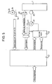
- Figure 5 shows an embodiment of a control device for a continuous processing machine according to the present Invention.
- C3 denotes a drive controller for the Drive unit A1 of the processing unit.
- the controller C3 receives from the position sensor S1 of the processing unit corresponding to the position of the processing unit Sensor signals that indicate the actual position of the agent.
- the Controller C3 also receives position specifications, i.e. Position setpoints and controls the via the drive unit A1 Position of the means such that the sensor S1 displayed position of the agent as well as possible Position specification met.
- C2 denotes an arithmetic unit, which serves the Calculate position setpoints for controller C3. Moreover The computing unit C2 takes over the function of detecting whether the agent is managed in the specified tolerance zone or Not.
- the computing unit receives C2 the sensor signals of the displacement sensor Gv of the Drive unit Av driven workpiece conveyor, and also the sensor signals from the sensor Sv Workpiece detection.
- the computing unit C2 also receives Part specification data that shows, for example, on which Location of the workpiece relative to that of the sensor Sv and / or the workpiece position of the sensor Gv Intervention of the agent should take place. For example, give this part specification data, at what distance from that of Sensor Sv detectable workpiece leading edge a hole set, a fitting is installed or a groove is milled should.
- Computing unit C2 is now able for the drive controller of the Using a setpoint to calculate the movement of the agent in the tolerance zone, according to the movement of the Workpiece. From the position sensor S1 of the position signal given to the computing unit C2 the computing unit C2 can also determine whether the mean is already in the specified tolerance zone or Not. This can be seen, for example, from the comparison between that calculated by the computing unit C2 Setpoint output to controller C3 and that from the position sensor Determine the displayed actual position of the agent S1.
- the Computing unit C2 determines that the mean in the specified tolerance zone is performed, the Computing unit C2 according to that shown in Figure 5 Embodiment a reconfiguration of the drive controller C3 through to the movement of the agent in the given Tolerance zone overlay a fine movement that leads to a precise alignment of the position of the agent with the position on the workpiece where the intervention is to take place.
- the Agent relative to Computing unit C2 receives the Sensor signal from the fine position sensor S2, which in this Embodiment a relative position between the workpiece and indicates means from which the deviation of the means from the engaged position.
- the computing unit C2 can now output the setpoint to the drive controller C3 accordingly, so that the Controller C3 the fine positioning of the agent according to the make the corrected position setpoint to controller C3 can.
- this is from the Fine position sensor S2 output fine position signal of the Used relative to the workpiece, the setpoint, which the computing unit C2 from the signals from the sensors Sv and Gv calculated for workpiece detection, a correction quantity according to the signal output from the fine position sensor S2 to superimpose, so that from the computing device C2 to the Controller C3 given corrected setpoint output one movement of the mean within the tolerance zone describes the one Fine movement for precise positioning of the agent relative is superimposed on the workpiece.
- This setpoint specification of Superimposed movements is controlled by the drive controller C3 Using the drive unit A1 and the sensor S1 in a corresponding actual movement of the agent implemented.
- the Control gain of drive controller C3 increases as soon as that Means related to the workpiece passing through within the specified tolerance zone is performed.
- the corrected setpoint output from the computing device C2 on the C3 controller can be carried out faster and more precisely, without the increased control speed and precision in the second phase of processing to disadvantageous, increased Overshoot of the controller in the first phase of processing leads in which the target-actual value deviations are significant can be larger than in the second, the fine positioning serving processing phase.
Landscapes
- Engineering & Computer Science (AREA)
- Life Sciences & Earth Sciences (AREA)
- General Physics & Mathematics (AREA)
- Automation & Control Theory (AREA)
- Forests & Forestry (AREA)
- Wood Science & Technology (AREA)
- Manufacturing & Machinery (AREA)
- Physics & Mathematics (AREA)
- Mechanical Engineering (AREA)
- Human Computer Interaction (AREA)
- General Engineering & Computer Science (AREA)
- Quality & Reliability (AREA)
- Control Of Conveyors (AREA)
- Veneer Processing And Manufacture Of Plywood (AREA)
- Dovetailed Work, And Nailing Machines And Stapling Machines For Wood (AREA)
- Feeding Of Workpieces (AREA)
- Grinding Of Cylindrical And Plane Surfaces (AREA)
- Automatic Control Of Machine Tools (AREA)
Description
- Figur 1
- zeigt ein Geschwindigkeits-Wegdiagramm zur Erläuterung eines Werkstückbearbeitungsablaufes gemäß der vorliegenden Erfindung;
- Figur 2
- zeigt eine schematische Darstellung eines Ausführungsbeispiels einer Durchlaufmaschine zur Bearbeitung von plattenförmigen Werkstücken gemäß der vorliegenden Erfindung;
- Figur 3
- zeigt eine schematische Darstellung eines Bearbeitungsaggregates in Form einer Vorrichtung zur Anb ringung von Kantenmaterial bei einer Durchlaufmaschine gemäß der vorliegenden Erfindung;
- Figur 4
- zeigt eine schematische Darstellung eines Bearbeitungsaggregates in Form eines Kappaggregates bei einer Durchlaufmaschine gemäß der vorliegenden Erfindung; und
- Figur 5
- zeigt ein Ausführungsbeispiel einer Steuervorrichtung für eine Durchlaufmaschine gemäß der vorliegenden Erfindung.
Claims (22)
- Verfahren zum Bearbeiten von plattenförmigen Werkstücken (T1,T2,T3) aus Holz, Holzwerkstoffen, Kunststoff oder dergleichen, bei dem die Werkstücke erfaßt, kontinuierlich entlang einer Bearbeitungsstrecke (B) geführt und dabei mit mindestens einem an der Bearbeitungsstrecke entlanggeführten Mittel zur Bearbeitung in Eingriff gebracht werden, wobeizur Relativpositionierung des mit dem jeweiligen Werkstück in Eingriff zu bringenden Mittels in einer ersten Phase über eine Steuereinrichtung (C1) das Mittel gegenüber dem jeweiligen Werkstück (T1,T2) hinsichtlich Relativbewegung und -position in eine vorgegebene Toleranzzone geführt wird,nach Erreichen der Toleranzzone der Bewegung des Mittels in einer weiteren Phase eine Feinbewegung bis zu einer Feinpositionierung des Mittels überlagert wird, undnach der Feinpositionierung der Eingriff durchgeführt wird.
- Verfahren nach Anspruch 1,
dadurch gekennzeichnet, daß die Steuereinrichtung (C1) zur Führung des Mittels in die Toleranzzone die Schritte durchführt:sensorisch (Sv) Erfassen der Position des Werkstückes (T1,T2,T3);Einwirken (A1) auf die Position des Mittels derart, daß das Mittel in die Toleranzzone geführt und darin gehalten wird. - Verfahren nach Anspruch 2, dadurch gekennzeichnet, daß die Steuervorrichtung die folgenden Schritte ausführt:Berechnen einer Positionsvorgabe für das Mittel;sensorisch Erfassen (S1) der Position des Mittels;Regeln der Position des Mittels auf die Positionsvorgabe.
- Verfahren nach Anspruch 2 oder 3,
dadurch gekennzeichnet, daß die Steuereinrichtung zur Feinpositionierung die Schritte durchführt:Erfassen, ob das Mittel in der Toleranzzone geführt wird; undfalls das Mittel in der Toleranzzone geführt wird, Einwirken auf die Position des Mittels derart, daß diese mit einer Referenzposition des Werkstückes in Übereinstimmung gebracht wird. - Verfahren nach Anspruch 4, daurch gekennzeichnet, daß die Steuereinrichtung die folgenden Schritte ausführt:Erfassen (S2;Sv,Gv) einer Feinposition des Werkstückes (T1,T2,T3);Berechnen einer Feinpositionsvorgabe für das Mittel aus der erfaßten Feinposition des Werkstückes;Regeln der Position des Mittels auf die Feinpositionsvorgabe.
- Verfahren nach Anspruch 4 oder 5, dadurch gekennzeichnet, daß die Erfassung der Feinposition des Werkstückes über einen gesonderten Feinpositionssensor (S2, Sv) vorgenommen wird.
- Verfahren nach einem der Ansprüche 4 bis 6, dadurch gekennzeichnet, daß die Feinposition des Werkstückes relativ zur Position des Mittels erfaßt wird (S2).
- Verfahren nach einem der Ansprüche 4 bis 6, dadurch gekennzeichnet, daß die Feinposition des Werkstückes relativ zu einem Maschinenchassis erfaßt wird (Sv).
- Verfahren nach Anspruch 8, gekennzeichnet durch eine Erfassung einer Feinposition des Mittels relativ zu einem Maschinenchassis durch einen gesonderten Feinpositionssensor (S2).
- Verfahren nach einem der Ansprüche 5 bis 9, dadurch gekennzeichnet, daß die Regelung des Mittels auf die Positionsvorgabe und die Regelung des Mittels auf die Feinpositionsvorgabe von demselben Regler (C3) durchgeführt wird.
- Verfahren nach Anspruch 10, dadurch gekennzeichnet, daß nachdem das Mittel die Toleranzzone erreicht hat, eine Regelcharakteristik des Reglers (C3) umgeschaltet wird.
- Vorrichtung zur Durchführung des Verfahren nach einem oder mehreren der Ansprüche 1 bis 11, miteiner Fördereinrichtung (Av, B) zum Erfassen und kontinuierlichen Führen der Werkstücke (T1, T2, T3) entlang einer Bearbeitungsstrecke,sowie mindestens einem im Bereich der Fördereinrichtung angeordneten Bearbeitungsaggregat (A1) mit mindestens einem Mittel (A2, K), welches zur Bearbeitung eines Werkstückes mit diesem in Eingriff gebracht werden kann;einer ersten Steuereinrichtung (C1), welche ausgebildet ist, zur Relativpositionierung des mit dem jeweiligen Werkstück in Eingriff zu bringenden Mittels in einer ersten Phase gegenüber dem jeweiligen Werkstück (T1,T2,T3) hinsichtlich Relativbewegung und -position das Mittel in eine vorgegebene Toleranzzone zu führen, undeiner zusätzlichen Steuereinrichtung, welche ausgebildet ist, nach Erreichen der Toleranzzone der Bewegung des Mittels in einer weiteren Phase eine Feinbewegung bis zu einer Feinpositionierung des Mittels zu überlagern.
- Vorrichtung nach Anspruch 12, dadurch gekennzeichnet, daß die erste Steuereinrichtung zur Führung des Mittels in die Toleranzzone umfaßt:einen Sensor (Gv, Sv) zur Erfassung der Position des Werkstückes; undeinen Aktor (A1) zur Einwirkung auf die Position des Mittels derart, daß das Mittel in die Toleranzzone geführt und darin gehalten wird.
- Vorrichtung nach Anspruch 13,
dadurch gekennzeichnet, daß die erste Steuervorrichtung umfaßt :einen Rechner (C2) zur Berechnung einer Positionsvorgabe für das Mittel;einen Sensor (S1) zur Erfassung der Position des Mittels; undeinen Regler (C3) zur Regelung der Position des Mittels auf die Positionsvorgabe. - Vorrichtung nach Anspruch 13 oder 14,
dadurch gekennzeichnet, daß die Steuereinrichtung umfaßt:Einrichtungen (C2) zur Erfassung, ob das Mittel in der Toleranzzone geführt wird; undEinrichtungen (A1,C3), die ausgebildet sind, auf die Position des Mittels derart einzuwirken, daß diese mit einer Referenzposition des Werkstücks in Übereinstimmung gebracht wird, falls das Mittel in der Toleranzzone geführt wird. - Vorrichtung nach Anspruch 15,
dadurch gekennzeichnet, daß die Steuereinrichtung umfaßt:eine Einrichtung (S2,Sv) zur Erfassung einer Feinposition des Werkstückes (T1 bis T3);eine Einrichtung (C2) zur Berechnung einer Feinpositionsvorgabe für das Mittel aus der erfaßten Feinposition des Werkstückes; undeinen Regler (C3) zur Regelung der Position des Mittels auf die Feinpositionsvorgabe. - Vorrichtung nach Anspruch 15 oder 16,
dadurch gekennzeichnet, daß zur Erfassung der Feinposition des Werkstückes ein gesonderter Feinpositionssensor (Sv,S2) vorgesehen ist. - Vorrichtung nach Anspruch 16 oder 17,
dadurch gekennzeichnet, daß die Einrichtung (S2) zur Erfassung der Feinposition des Werkstückes (T1) derart angeordnet ist, daß die Feinposition des Werkstückes relativ zur Position des Mittels erfaßt wird. - Vorrichtung nach Anspruch 16 oder 17,
dadurch gekennzeichnet, daß die Einrichtung (Sv) zur Erfassung der Feinposition des Werkstückes derart angeordnet ist, daß die Feinposition des Werkstückes relativ zu einem Maschinenchassis erfaßt wird. - Vorrichtung nach Anspruch 19,
gekennzeichnet durch einen gesonderten Feinpositionssensor (S2) zur Erfassung einer Feinposition des Mittels relativ zu einem Maschinenchassis. - Vorrichtung nach einem der Ansprüche 16 bis 20, gekennzeichnet durch einen Regler (C3), der ausgebildet ist, sowohl die Regelung des Mittels auf die Positionsvorgabe als auch die Regelung des Mittels auf die Feinpositionsvorgabe gemäß jeweiliger Konfigurationsvorgaben durchzuführen.
- Vorrichtung nach Anspruch 21,
gekennzeichnet durch eine Einrichtung (C2) zum Umkonfigurieren der Regelcharakteristik des Reglers, nachdem das Mittel die Toleranzzone erreicht hat.
Applications Claiming Priority (3)
| Application Number | Priority Date | Filing Date | Title |
|---|---|---|---|
| DE19741163 | 1997-09-18 | ||
| DE19741163A DE19741163C2 (de) | 1997-09-18 | 1997-09-18 | Verfahren und Vorrichtung zur Durchlaufbearbeitung von plattenförmigen Werkstücken |
| PCT/EP1998/005833 WO1999014645A1 (de) | 1997-09-18 | 1998-09-14 | Verfahren und vorrichtung zur durchlaufbearbeitung von plattenförmigen werkstücken |
Publications (2)
| Publication Number | Publication Date |
|---|---|
| EP1015947A1 EP1015947A1 (de) | 2000-07-05 |
| EP1015947B1 true EP1015947B1 (de) | 2003-06-25 |
Family
ID=7842814
Family Applications (1)
| Application Number | Title | Priority Date | Filing Date |
|---|---|---|---|
| EP98948970A Expired - Lifetime EP1015947B1 (de) | 1997-09-18 | 1998-09-14 | Verfahren und vorrichtung zur durchlaufbearbeitung von plattenförmigen werkstücken |
Country Status (5)
| Country | Link |
|---|---|
| EP (1) | EP1015947B1 (de) |
| AT (1) | ATE243859T1 (de) |
| DE (2) | DE19741163C2 (de) |
| ES (1) | ES2201536T3 (de) |
| WO (1) | WO1999014645A1 (de) |
Cited By (2)
| Publication number | Priority date | Publication date | Assignee | Title |
|---|---|---|---|---|
| CN105563563A (zh) * | 2014-11-04 | 2016-05-11 | 米夏埃尔·魏尼希有限公司 | 用于监控加工机的机器空间的方法以及加工机 |
| EP3815863B1 (de) * | 2019-11-04 | 2026-03-25 | SCM Group S.p.A. | Kontrollverfahren für eine kantenanleimmaschine, und kantenanleimmaschine |
Families Citing this family (16)
| Publication number | Priority date | Publication date | Assignee | Title |
|---|---|---|---|---|
| ITRN20030009A1 (it) * | 2003-04-01 | 2004-10-02 | Scm Group Spa | Dispositivo ottico e sistema computerizzato per acquisizione di profili di pezzi su macchina per bordare pannelli in legno. |
| DE10323266B3 (de) | 2003-05-23 | 2004-12-09 | Ima Klessmann Gmbh Holzbearbeitungssysteme | Kantenanleimaggregat für eine programmgesteuerte Maschine |
| DE102005014651B4 (de) * | 2005-03-31 | 2009-01-02 | Homag Holzbearbeitungssysteme Ag | Verfahren und Vorrichtung zum Bearbeiten von plattenförmigen Werkstücken |
| ES2349421T3 (es) * | 2006-05-24 | 2011-01-03 | Homag Holzbearbeitungssysteme Ag | Dispositivo de identificación para la gestión de recursos de productos contínuos por metros. |
| ITMO20060270A1 (it) * | 2006-09-06 | 2008-03-07 | Scm Group Spa | Macchina operatrice |
| PL2085848T3 (pl) * | 2008-01-31 | 2011-09-30 | Homag Holzbearbeitungssysteme Ag | Zespół obróbczy i sposób obróbki obiektów poprzez pomiar czasu |
| DE202009007193U1 (de) * | 2009-05-19 | 2010-11-11 | Homag Holzbearbeitungssysteme Ag | Bearbeitungsvorrichtung |
| DE202011102996U1 (de) | 2011-07-05 | 2011-08-29 | Wago Verwaltungsgesellschaft Mbh | Federkraftklemmkontakt und Klemmenbauelement |
| DE102015219257A1 (de) * | 2015-10-06 | 2017-04-06 | Homag Gmbh | Bearbeitungsmaschine und Verfahren zur Bearbeitung von Werkstücken |
| DE102016204249A1 (de) | 2016-03-15 | 2017-09-21 | Homag Gmbh | Vorrichtung zum Bearbeiten und/oder Beschichten eines Werkstücks |
| DE102016219265A1 (de) * | 2016-10-05 | 2018-04-05 | Homag Gmbh | Vorrichtung und Verfahren zum Bearbeiten eines Werkstücks |
| DE102016224037A1 (de) * | 2016-12-02 | 2018-06-07 | Weeke Bohrsysteme Gmbh | Bearbeitungsvorrichtung zur Durchlaufbearbeitung, Steuereinrichtung und Verfahren |
| DE102017116884A1 (de) * | 2017-07-26 | 2019-01-31 | Homag Gmbh | Bearbeitungsvorrichtung und Bearbeitungsverfahren |
| DE102020121850A1 (de) * | 2020-08-20 | 2022-02-24 | Homag Gmbh | Verfahren zum Bearbeiten von Werkstücken, Steuerungseinrichtung für eine Bearbeitungseinrichtung sowie Bearbeitungseinrichtung |
| DE102020130145A1 (de) | 2020-11-16 | 2022-05-19 | Homag Gmbh | Beschichtungsvorrichtung sowie Verfahren |
| DE102023112494A1 (de) | 2023-05-11 | 2024-11-14 | Homag Plattenaufteiltechnik Gmbh | Verfahren zum Betreiben einer Plattenbearbeitungsanlage, Plattenbearbeitungsanlage, sowie Steuereinrichtung für eine Plattenbearbeitungsanlage |
Family Cites Families (2)
| Publication number | Priority date | Publication date | Assignee | Title |
|---|---|---|---|---|
| DE3302177A1 (de) * | 1982-02-16 | 1983-08-25 | Diffracto Ltd., Windsor, Ontario | Verfahren und einrichtung zur automatischen handhabung oder bearbeitung oder zum automatischen zusammenbau von gegenstaenden |
| JPS60144806A (ja) * | 1984-01-09 | 1985-07-31 | Fanuc Ltd | ロボツトのライントラツキング制御方法 |
-
1997
- 1997-09-18 DE DE19741163A patent/DE19741163C2/de not_active Expired - Fee Related
-
1998
- 1998-09-14 WO PCT/EP1998/005833 patent/WO1999014645A1/de not_active Ceased
- 1998-09-14 EP EP98948970A patent/EP1015947B1/de not_active Expired - Lifetime
- 1998-09-14 DE DE59808839T patent/DE59808839D1/de not_active Expired - Lifetime
- 1998-09-14 AT AT98948970T patent/ATE243859T1/de not_active IP Right Cessation
- 1998-09-14 ES ES98948970T patent/ES2201536T3/es not_active Expired - Lifetime
Cited By (2)
| Publication number | Priority date | Publication date | Assignee | Title |
|---|---|---|---|---|
| CN105563563A (zh) * | 2014-11-04 | 2016-05-11 | 米夏埃尔·魏尼希有限公司 | 用于监控加工机的机器空间的方法以及加工机 |
| EP3815863B1 (de) * | 2019-11-04 | 2026-03-25 | SCM Group S.p.A. | Kontrollverfahren für eine kantenanleimmaschine, und kantenanleimmaschine |
Also Published As
| Publication number | Publication date |
|---|---|
| EP1015947A1 (de) | 2000-07-05 |
| DE59808839D1 (de) | 2003-07-31 |
| DE19741163C2 (de) | 2002-10-10 |
| DE19741163A1 (de) | 1999-04-01 |
| WO1999014645A1 (de) | 1999-03-25 |
| ES2201536T3 (es) | 2004-03-16 |
| ATE243859T1 (de) | 2003-07-15 |
Similar Documents
| Publication | Publication Date | Title |
|---|---|---|
| DE19741163C2 (de) | Verfahren und Vorrichtung zur Durchlaufbearbeitung von plattenförmigen Werkstücken | |
| DE3223231C2 (de) | Automatische Nachführeinrichtung und Verfahren zum automatischen Nachführen eines Arbeitsgebildes | |
| DE4211218C2 (de) | Einrichtung und Verfahren zum automatischen abschnittsweisen Schneiden von Flachmaterial | |
| DE3916143C2 (de) | Schneidmaschine und Verfahren zum Anordnen eines Werkstückes in dieser | |
| EP1127665B1 (de) | Maschine zum Bearbeiten von Werkstücken aus Holz, Kunststoff und dergleichen, insbesondere Kehlmaschine, sowie Verfahren zur Einstellung einer solchen Maschine | |
| EP0195289A1 (de) | Verfahren zum Bearbeiten von Werkstücken, insbesondere zum thermischen Trennen von Profilen mit einem Schneidbrenner | |
| DE102008036473B3 (de) | Verfahren und Vorrichtung zum Schneiden von Glasscheiben, Computerprogramm und maschinenlesbarer Träger | |
| EP1166977B1 (de) | Schneidmaschine zum selbsttätigen Beschneiden von Druckerzeugnissen | |
| EP2098343B1 (de) | Bearbeitungsvorrichtung | |
| DE4243054C1 (de) | Vorrichtung zur Bearbeitung der Kantenränder von fortlaufend bewegten plattenförmigen Werkstücken | |
| EP4000832A1 (de) | Beschichtungsvorrichtung sowie verfahren | |
| DE19719196A1 (de) | Verfahren und Vorrichtung zur Anfertigung von Zuschnitten aus fehlerhaften, flächigen biegeschlaffen Werkstoffen | |
| EP1387743B1 (de) | Kantenfräsaggregat für eine programmgesteuerte durchlaufmaschine | |
| DE3640675C2 (de) | ||
| EP1716990A1 (de) | Bearbeitungseinheit an einer im Durchlauf arbeitenden Holzbearbeitungsmaschine | |
| WO2020120352A1 (de) | Verfahren zum verarbeiten plattenförmiger werkstücke | |
| EP3098680A1 (de) | Verfahren und werkzeugmaschine mit mehreren bearbeitungseinrichtungen zur bearbeitung eines profilträgers | |
| DE202020104273U1 (de) | Sägeanlage zum Sägen eines Sägeguts | |
| EP4319937A1 (de) | Werkstücktransportvorrichtung, plattenbearbeitungsanlage sowie verfahren zum betreiben einer werkstücktransportvorrichtung | |
| DE102020103192B4 (de) | Sägeanlage und Verfahren zum Sägen eines Sägeguts | |
| EP3487652B1 (de) | Bearbeitungsvorrichtung und bearbeitungsverfahren | |
| EP3922422A1 (de) | Verfahren zum verarbeiten plattenförmiger werkstücke | |
| DE19642923A1 (de) | Doppelgehrungssäge | |
| EP3888841B1 (de) | Verfahren und maschinelle anordnung zum trennenden bearbeiten eines plattenartigen werkstücks, und entsprechenden computerprogramm | |
| EP1707311B1 (de) | Verfahren und Vorrichtung zum Bearbeiten von plattenförmigen Werkstücken |
Legal Events
| Date | Code | Title | Description |
|---|---|---|---|
| PUAI | Public reference made under article 153(3) epc to a published international application that has entered the european phase |
Free format text: ORIGINAL CODE: 0009012 |
|
| 17P | Request for examination filed |
Effective date: 20000330 |
|
| AK | Designated contracting states |
Kind code of ref document: A1 Designated state(s): AT DE ES IT |
|
| 17Q | First examination report despatched |
Effective date: 20020109 |
|
| GRAG | Despatch of communication of intention to grant |
Free format text: ORIGINAL CODE: EPIDOS AGRA |
|
| GRAG | Despatch of communication of intention to grant |
Free format text: ORIGINAL CODE: EPIDOS AGRA |
|
| GRAH | Despatch of communication of intention to grant a patent |
Free format text: ORIGINAL CODE: EPIDOS IGRA |
|
| GRAH | Despatch of communication of intention to grant a patent |
Free format text: ORIGINAL CODE: EPIDOS IGRA |
|
| GRAA | (expected) grant |
Free format text: ORIGINAL CODE: 0009210 |
|
| AK | Designated contracting states |
Designated state(s): AT DE ES IT |
|
| REF | Corresponds to: |
Ref document number: 59808839 Country of ref document: DE Date of ref document: 20030731 Kind code of ref document: P |
|
| REG | Reference to a national code |
Ref country code: ES Ref legal event code: FG2A Ref document number: 2201536 Country of ref document: ES Kind code of ref document: T3 |
|
| PLBE | No opposition filed within time limit |
Free format text: ORIGINAL CODE: 0009261 |
|
| STAA | Information on the status of an ep patent application or granted ep patent |
Free format text: STATUS: NO OPPOSITION FILED WITHIN TIME LIMIT |
|
| 26N | No opposition filed |
Effective date: 20040326 |
|
| PGFP | Annual fee paid to national office [announced via postgrant information from national office to epo] |
Ref country code: AT Payment date: 20040930 Year of fee payment: 7 |
|
| PG25 | Lapsed in a contracting state [announced via postgrant information from national office to epo] |
Ref country code: AT Free format text: LAPSE BECAUSE OF NON-PAYMENT OF DUE FEES Effective date: 20050914 |
|
| PGFP | Annual fee paid to national office [announced via postgrant information from national office to epo] |
Ref country code: ES Payment date: 20090916 Year of fee payment: 12 |
|
| PGFP | Annual fee paid to national office [announced via postgrant information from national office to epo] |
Ref country code: DE Payment date: 20100922 Year of fee payment: 13 |
|
| PG25 | Lapsed in a contracting state [announced via postgrant information from national office to epo] |
Ref country code: IT Free format text: LAPSE BECAUSE OF NON-PAYMENT OF DUE FEES Effective date: 20100914 |
|
| PGRI | Patent reinstated in contracting state [announced from national office to epo] |
Ref country code: IT Effective date: 20110616 |
|
| REG | Reference to a national code |
Ref country code: ES Ref legal event code: FD2A Effective date: 20111019 |
|
| PG25 | Lapsed in a contracting state [announced via postgrant information from national office to epo] |
Ref country code: ES Free format text: LAPSE BECAUSE OF NON-PAYMENT OF DUE FEES Effective date: 20100915 |
|
| PGFP | Annual fee paid to national office [announced via postgrant information from national office to epo] |
Ref country code: IT Payment date: 20110923 Year of fee payment: 14 |
|
| PG25 | Lapsed in a contracting state [announced via postgrant information from national office to epo] |
Ref country code: DE Free format text: LAPSE BECAUSE OF NON-PAYMENT OF DUE FEES Effective date: 20130403 |
|
| PG25 | Lapsed in a contracting state [announced via postgrant information from national office to epo] |
Ref country code: IT Free format text: LAPSE BECAUSE OF NON-PAYMENT OF DUE FEES Effective date: 20120914 |
|
| REG | Reference to a national code |
Ref country code: DE Ref legal event code: R119 Ref document number: 59808839 Country of ref document: DE Effective date: 20130403 |