EP1015824B1 - Nonimaging solar collector - Google Patents
Nonimaging solar collector Download PDFInfo
- Publication number
- EP1015824B1 EP1015824B1 EP98946104A EP98946104A EP1015824B1 EP 1015824 B1 EP1015824 B1 EP 1015824B1 EP 98946104 A EP98946104 A EP 98946104A EP 98946104 A EP98946104 A EP 98946104A EP 1015824 B1 EP1015824 B1 EP 1015824B1
- Authority
- EP
- European Patent Office
- Prior art keywords
- solar collector
- reflector
- absorber
- fin
- asymmetrically
- Prior art date
- Legal status (The legal status is an assumption and is not a legal conclusion. Google has not performed a legal analysis and makes no representation as to the accuracy of the status listed.)
- Expired - Lifetime
Links
- 239000006096 absorbing agent Substances 0.000 claims description 42
- 239000004020 conductor Substances 0.000 claims description 22
- 230000005855 radiation Effects 0.000 claims description 3
- 238000000926 separation method Methods 0.000 claims 1
- 239000000463 material Substances 0.000 description 7
- 238000002835 absorbance Methods 0.000 description 6
- 229910052751 metal Inorganic materials 0.000 description 5
- 239000002184 metal Substances 0.000 description 5
- 239000000758 substrate Substances 0.000 description 5
- VYPSYNLAJGMNEJ-UHFFFAOYSA-N Silicium dioxide Chemical compound O=[Si]=O VYPSYNLAJGMNEJ-UHFFFAOYSA-N 0.000 description 4
- 239000011521 glass Substances 0.000 description 4
- 238000004519 manufacturing process Methods 0.000 description 4
- 238000000034 method Methods 0.000 description 4
- 229910010421 TiNx Inorganic materials 0.000 description 3
- 238000000576 coating method Methods 0.000 description 3
- 238000010276 construction Methods 0.000 description 3
- RYGMFSIKBFXOCR-UHFFFAOYSA-N Copper Chemical compound [Cu] RYGMFSIKBFXOCR-UHFFFAOYSA-N 0.000 description 2
- 229910052782 aluminium Inorganic materials 0.000 description 2
- XAGFODPZIPBFFR-UHFFFAOYSA-N aluminium Chemical compound [Al] XAGFODPZIPBFFR-UHFFFAOYSA-N 0.000 description 2
- 229910052681 coesite Inorganic materials 0.000 description 2
- 229910052802 copper Inorganic materials 0.000 description 2
- 239000010949 copper Substances 0.000 description 2
- 229910052906 cristobalite Inorganic materials 0.000 description 2
- 239000003989 dielectric material Substances 0.000 description 2
- 239000000377 silicon dioxide Substances 0.000 description 2
- 238000001228 spectrum Methods 0.000 description 2
- 229910052682 stishovite Inorganic materials 0.000 description 2
- 229910052905 tridymite Inorganic materials 0.000 description 2
- 230000005457 Black-body radiation Effects 0.000 description 1
- 238000010521 absorption reaction Methods 0.000 description 1
- 238000009825 accumulation Methods 0.000 description 1
- 239000000919 ceramic Substances 0.000 description 1
- 239000011195 cermet Substances 0.000 description 1
- 239000011248 coating agent Substances 0.000 description 1
- 239000012141 concentrate Substances 0.000 description 1
- 238000006073 displacement reaction Methods 0.000 description 1
- 239000002019 doping agent Substances 0.000 description 1
- 230000002349 favourable effect Effects 0.000 description 1
- 239000012530 fluid Substances 0.000 description 1
- 235000015243 ice cream Nutrition 0.000 description 1
- 238000005259 measurement Methods 0.000 description 1
- 239000000203 mixture Substances 0.000 description 1
- 238000001771 vacuum deposition Methods 0.000 description 1
Images


Classifications
-
- F—MECHANICAL ENGINEERING; LIGHTING; HEATING; WEAPONS; BLASTING
- F24—HEATING; RANGES; VENTILATING
- F24S—SOLAR HEAT COLLECTORS; SOLAR HEAT SYSTEMS
- F24S10/00—Solar heat collectors using working fluids
- F24S10/40—Solar heat collectors using working fluids in absorbing elements surrounded by transparent enclosures, e.g. evacuated solar collectors
- F24S10/45—Solar heat collectors using working fluids in absorbing elements surrounded by transparent enclosures, e.g. evacuated solar collectors the enclosure being cylindrical
-
- F—MECHANICAL ENGINEERING; LIGHTING; HEATING; WEAPONS; BLASTING
- F24—HEATING; RANGES; VENTILATING
- F24S—SOLAR HEAT COLLECTORS; SOLAR HEAT SYSTEMS
- F24S10/00—Solar heat collectors using working fluids
- F24S10/70—Solar heat collectors using working fluids the working fluids being conveyed through tubular absorbing conduits
- F24S10/75—Solar heat collectors using working fluids the working fluids being conveyed through tubular absorbing conduits with enlarged surfaces, e.g. with protrusions or corrugations
-
- F—MECHANICAL ENGINEERING; LIGHTING; HEATING; WEAPONS; BLASTING
- F24—HEATING; RANGES; VENTILATING
- F24S—SOLAR HEAT COLLECTORS; SOLAR HEAT SYSTEMS
- F24S23/00—Arrangements for concentrating solar-rays for solar heat collectors
- F24S23/70—Arrangements for concentrating solar-rays for solar heat collectors with reflectors
- F24S23/80—Arrangements for concentrating solar-rays for solar heat collectors with reflectors having discontinuous faces
-
- F—MECHANICAL ENGINEERING; LIGHTING; HEATING; WEAPONS; BLASTING
- F24—HEATING; RANGES; VENTILATING
- F24S—SOLAR HEAT COLLECTORS; SOLAR HEAT SYSTEMS
- F24S70/00—Details of absorbing elements
- F24S70/20—Details of absorbing elements characterised by absorbing coatings; characterised by surface treatment for increasing absorption
-
- Y—GENERAL TAGGING OF NEW TECHNOLOGICAL DEVELOPMENTS; GENERAL TAGGING OF CROSS-SECTIONAL TECHNOLOGIES SPANNING OVER SEVERAL SECTIONS OF THE IPC; TECHNICAL SUBJECTS COVERED BY FORMER USPC CROSS-REFERENCE ART COLLECTIONS [XRACs] AND DIGESTS
- Y02—TECHNOLOGIES OR APPLICATIONS FOR MITIGATION OR ADAPTATION AGAINST CLIMATE CHANGE
- Y02E—REDUCTION OF GREENHOUSE GAS [GHG] EMISSIONS, RELATED TO ENERGY GENERATION, TRANSMISSION OR DISTRIBUTION
- Y02E10/00—Energy generation through renewable energy sources
- Y02E10/40—Solar thermal energy, e.g. solar towers
- Y02E10/44—Heat exchange systems
Definitions
- the present invention is concerned with a nonimaging concentrator for light. More particularly, the invention is concerned with a solar energy concentrator or collector having an absorber disposed within a glass housing and a reflector asymmetrically disposed in the housing enabling improved nonimaging light concentration, such as an evacuated cylindrical reflector tube.
- This absorber geometry can also include a gap loss reduction V groove which can be positioned in an asymmetric manner relative to a wedge shaped heat conductor fin coupled to the absorber.
- Nonimaging concentrators and their advantages are well known in the art (see, for example, U.S. Pat. Nos. 3,957,031; 4,002,499;4,003,638;4,230,095;4,387,961; 4,359,265; and 5,289,356).
- the device is constructed using a given absorber shape, usually a cylindrical tube, and then the appropriate nonimaging reflector is designed. This emphasis was therefore primarily on developing new reflector designs to optimize collector efficiency.
- Nonimaging solar collectors constructed in accordance with the various forms of the invention are shown in F S. 3-5 and indicated generally at 10.
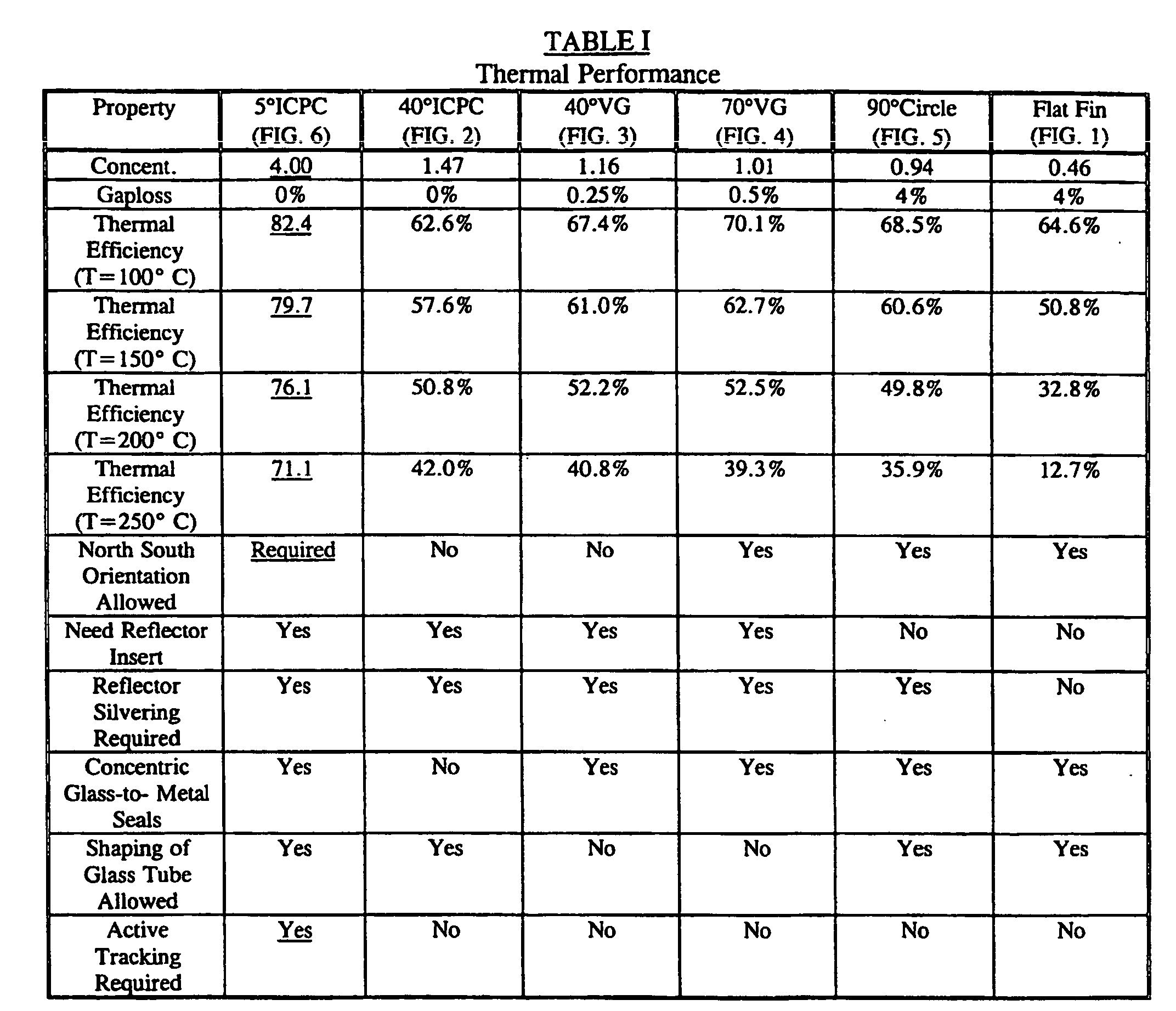
- a prior art collector design is shown for comparison in FIG. 1.
- the prior art collector 12 of FIG. 1 has heat conductor fins 14 and 16 which both radiate heat so that thermal performance is poor at temperatures above about 100°C.
- a first reflector 32 and second reflector 32' are asymmetrically disposed relative to the cusp absorber 20. This asymmetric structure has enabled improved efficiency of collection.
- the absorber 20 is also noncentrically disposed
- the nonimaging solar collector 10 of FIGS. 3A-3C includes an outer glass tube housing 24 which is transparent, allowing entry of light rays 26 into the evacuated interior of the housing 24.
- the housing 24 is shown as cylindrical in shape but can take on other geometries suitable for the functions described herein.
- the light rays 26 either directly strike absorber tube 28 or reflect from reflector surface 32 to impinge upon the absorber tube 28 and thereby concentrate the collected light.
- this absorber tube 28 can be shapes other than shown in the figures but is concentrically positioned relative to the housing 24.
- the absorber tube 28 further includes a wedge shaped heat conductor 30 (see FIG. 3C) which in cross-section collectively appears with the absorber tube 28 as an "ice cream cone'' geometry, as noted in FIGS. 3A, 3B, 4 and 5.
- the heat conductor 30 can be rotated from the ⁇ /2 portion at "six o'clock" to other angular positions (shown in phantom as conductor 30'), and this results in improved collection efficiency.
- the irradiance on the heat conductor 30 (or 30') is from a distance of r/2 to r, where r is the radial length of the heat conductor 30 (or 30').
- the irradiance is more uniform as a consequence of the angle of light incidence. Better uniformity of irradiance improves heat transfer to a working fluid disposed within the conductor 30 (or 30') and thus improves performance.
- the reflector 32 (as in FIG. 2) is no longer symmetrically disposed in a mirror image location relative to a vertical plane along ⁇ /2.
- the reflector now comprises the reflector 32 and the reflector 32'. This asymmetry has further enabled achieving improved efficiency of solar collection.
- the degree of asymmetry between the reflector 32 and the reflector 32' can be adjusted depending on the orientation of incoming light to optimize efficiency.
- reflector surface 32 includes a gap loss reduction V-groove 34.
- This groove 34 suppresses energy absorption gap loss which would otherwise occur when there is a space between the reflector surface 32 and the wedge shaped heat conductor 30.
- the angle of acceptance for the absorber is about 40° which would make the collector 10 suitable for east-west orientation without need of any solar tracking mechanism.
- This particular angular acceptance with the associated V-groove 34 provides excellent tolerance for vertical positioning errors in placement of the absorber 30, as well as good tolerance for horizontal displacements (see FIG. 3D).
- a V-groove 34' is disposed in an asymmetric angular position (see FIGS. 3A and 4) which also improves collection efficiency.
- the heat conductor 30' is aligned with the V-groove 34' list can be asymmetrically positioned without loss of much efficiency.
- the collectors 10 of FIG. 4 have a smaller radius of curvature for the reflector surface 32 (or 32'), resulting in a wider, angle of acceptance (about 70°). This embodiment would allow the collector 10 to be suitable for north-south or east-west orientation without need of any solar tracking device.
- the collector 10 of FIG. 5 is the limiting case of the embodiments of FIGS. 3 and 4 where the radius of curvature of the reflector surface 32 is coincident with die inner surface of the glass tube housing 24.
- the embodiment with the heat conductor 30 at ⁇ /2 has an acceptance angle approaching 90°.
- This form of the collector 10 former simplifies the construction procedure for manufacture of the collector 10.
- the other embodiment having the heat conductor 30' at other angles also would be simple to manufacture.
- the reflector surface 32 (and 32') has a relatively large radius of curvature such that the angle of acceptance is about 5° and would require some crude solar tracking device, operative either continuously or intermittently.
- This design includes a small cusp arising from the small angle of acceptance. The thermal performance is quite good at elevated temperatures.
- FIG. 7 shows the efficiency of the symmetric reflector 32 versus incident angle of the symmetric reflector embodiment of FIGS. 6A and 6B for concentration factors of two, three, four and five with reflection or Fresnel losses ignored. Concentrations of about four are achieved with efficient 5° acceptance properties.
- Coatings can be, for example, cermets having a very low emittance (about 0.02 at 20°C) and a high absorbance (about 0.92) over the solar spectrum .
- Ceramicmets are conventional materials which have layers of dielectric materials which contain a particular fraction of metal composition disposed on a metal reflector layer having an anti-reflection coating. The top layers have lower metal fractions in the dielectric material than those layers below them. The higher metal fraction layer at the bottom absorbs more energy because visible Hight passes through the top layers easily.
- the emission of black body radiation (>2 mm wave length) is however reflected by the cermet dopant quite efficiently.
- emission of radiation from the bottom layer is trapped inside the absorber material, and only the low doped top layer radiates away heat.
- the graded metal content increases the amount of atoms seen by the incoming light so more is absorbed and also reduces the number of atoms which can radiate away hear.
- Another class of materials useful as absorbers are certain ceramics which can easily be made using vacuum deposition. For example, conventional layers of TiN x O y and SiO 2 /TiN x O y can be deposited onto an aluminum or copper substrate until a set amount of accumulation has been measured. Both of these types of materials have a TiN x O y layer about 53nm thick on a substrate.
- the above described preferred embodiments utilize a concentrically disposed absorber tube within a cylindrical reflector housing which has been evacuated.
- the absorber tube further includes a wedge shaped heat conduction fin coupled to the absorber, and preferably includes an absorber layer (absorbance greater than 0.90) with low emittance (less than above 0.05) to achieve a very efficient solar collector.
- the simplicity of this basic design allows easy manufacturing, reducing construction costs thereby making solar collector usage more practical.
Landscapes
- Engineering & Computer Science (AREA)
- Chemical & Material Sciences (AREA)
- Sustainable Development (AREA)
- Physics & Mathematics (AREA)
- Sustainable Energy (AREA)
- Thermal Sciences (AREA)
- Life Sciences & Earth Sciences (AREA)
- Combustion & Propulsion (AREA)
- Mechanical Engineering (AREA)
- General Engineering & Computer Science (AREA)
- Dispersion Chemistry (AREA)
- Optical Elements Other Than Lenses (AREA)
- Photovoltaic Devices (AREA)
- Telescopes (AREA)
- Endoscopes (AREA)
Description
Claims (11)
- A nonimaging solar collector (10) including, an absorber (28) disposed to receive radiation and a reflector element (32) asymmetrically disposed relative to said absorber (28), and characterized in that a heat conduction fin (30) is coupled to said absorber (28) and the fin (30) having a wedge shape tapering to lesser thickness as a function of increasing radial separation from said absorber (28) and directed at said reflector element (32), the heat conductor fin (30) being asymmetrically disposed relative to the reflector (32).
- The solar collector as defined in Claim 1 wherein said absorber is concentrically disposed relative to a housing (24).
- The solar collector (10) as defined in Claim 1 further including a housing (24) transparent to the radiation.
- The solar collector (10) as defined in Claim 1 wherein said asymmetrically disposed reflector element (32) comprises at least two reflector surfaces (32) and (32') each having different curvature.
- The solar collector (10) as defined in Claim 1 wherein said asymmetrically disposed reflector element (32) comprises two reflector surfaces of same curvature, each rotated about a point but for different angles of rotation thereby disposed asymmetrically relative to the absorber (28).
- The solar collector (10) as defined in Claim 1 further including a V-groove element (34) as part of said reflector element (32).
- The solar collector (10) as defined in Claim 6 wherein said heat conductor fin (30) includes a tapered end and said V-groove element (34) is symmetrically disposed relative to the tapered end of said heat conduction fin (30).
- The solar collector (10) as defined in Claim 6 wherein said heat conductor fin (30) includes a tapered end and said V-groove element (34) is symmetrically disposed relative to said fin (30) and both said fin (30) and said V-groove element (34) are asymmetrically disposed relative to said reflector (32).
- The solar collector (10) as defined in Claim 8 wherein the tapered end extends into said V-groove element (34).
- The solar collector (10) as defined in Claim 1 wherein said heat conductor fin (30) is asymmetrically displaced relative to a vertical plane of the solar collector (10).
- The solar collector (10) as defined in Claim 10 wherein said heat conductor fin (30) is displaced about π/2 from an angle defined by the vertical plane.
Applications Claiming Priority (3)
| Application Number | Priority Date | Filing Date | Title |
|---|---|---|---|
| US934090 | 1997-09-19 | ||
| US08/934,090 US5927271A (en) | 1997-09-19 | 1997-09-19 | Nonimaging solar collector |
| PCT/US1998/019477 WO1999014537A1 (en) | 1997-09-19 | 1998-09-17 | Nonimaging solar collector |
Publications (3)
| Publication Number | Publication Date |
|---|---|
| EP1015824A1 EP1015824A1 (en) | 2000-07-05 |
| EP1015824A4 EP1015824A4 (en) | 2001-05-16 |
| EP1015824B1 true EP1015824B1 (en) | 2005-11-16 |
Family
ID=25464942
Family Applications (1)
| Application Number | Title | Priority Date | Filing Date |
|---|---|---|---|
| EP98946104A Expired - Lifetime EP1015824B1 (en) | 1997-09-19 | 1998-09-17 | Nonimaging solar collector |
Country Status (8)
| Country | Link |
|---|---|
| US (3) | US5927271A (en) |
| EP (1) | EP1015824B1 (en) |
| CN (1) | CN1146711C (en) |
| AU (1) | AU736818B2 (en) |
| DE (1) | DE69832396T2 (en) |
| ES (1) | ES2252857T3 (en) |
| IL (1) | IL135141A (en) |
| WO (1) | WO1999014537A1 (en) |
Cited By (1)
| Publication number | Priority date | Publication date | Assignee | Title |
|---|---|---|---|---|
| CN116202237A (en) * | 2023-04-28 | 2023-06-02 | 昆明理工大学 | Solar vacuum tube photo-thermal performance monitoring device and monitoring method |
Families Citing this family (9)
| Publication number | Priority date | Publication date | Assignee | Title |
|---|---|---|---|---|
| KR100404338B1 (en) * | 2001-02-14 | 2003-11-03 | 모인에너지(주) | Design and Manufacture of solar Concentrator asymmetric Reflectors and bifacial Absorbers |
| US6668820B2 (en) | 2001-08-24 | 2003-12-30 | Solargenix Energy Llc | Multiple reflector solar concentrators and systems |
| US20040126594A1 (en) * | 2002-06-06 | 2004-07-01 | Carlo Rubbia | Surface coating for a collector tube of a linear parabolic solar concentrator |
| DE102005055858A1 (en) * | 2005-11-23 | 2007-05-24 | Göbel, Gerald, Dr. | Absorber for conversion of solar radiation into thermal energy consists mainly of non-porous dark ceramic material |
| RU2329437C1 (en) * | 2007-06-04 | 2008-07-20 | Борис Иванович Казанджан | Solar collector (options) and method of solar shell production |
| CA2704650A1 (en) * | 2009-05-19 | 2010-11-19 | John Bradley Deforge | Asymmetric solar collector system |
| TW201351674A (en) * | 2012-06-13 | 2013-12-16 | 財團法人工業技術研究院 | Solar power generation system and solar collector |
| JP6541169B2 (en) * | 2014-08-25 | 2019-07-10 | 三菱自動車工業株式会社 | Rear structure of vehicle |
| CN107228491A (en) * | 2017-05-31 | 2017-10-03 | 张绰 | A kind of asymmetric CPC composite parabolics internal focusing vacuum tube solar heat-collecting device of heated body glass tube acceptance angle |
Family Cites Families (15)
| Publication number | Priority date | Publication date | Assignee | Title |
|---|---|---|---|---|
| US4003638A (en) | 1973-12-28 | 1977-01-18 | The University Of Chicago | Radiant energy collection |
| US4002499A (en) | 1974-07-26 | 1977-01-11 | The United States Of America As Represented By The United States Energy Research And Development Administration | Radiant energy collector |
| US3957031A (en) | 1975-05-29 | 1976-05-18 | The United States Of America As Represented By The United States Energy Research And Development Administration | Light collectors in cylindrical geometry |
| US4059093A (en) * | 1975-09-22 | 1977-11-22 | Grumman Aerospace Corporation | Solar energy collector |
| US4230095A (en) | 1978-05-26 | 1980-10-28 | The United States Of America As Represented By The United States Department Of Energy | Ideal light concentrators with reflector gaps |
| US4286580A (en) * | 1979-06-11 | 1981-09-01 | Elmo Sitnam | Solar collector |
| US4246891A (en) * | 1979-09-12 | 1981-01-27 | General Electric Company | Low reflection loss cusp like reflector for solar energy collector |
| US4387961A (en) | 1980-01-18 | 1983-06-14 | Roland Winston | Compound parabolic concentrator with cavity for tubular absorbers |
| US4359265A (en) | 1980-01-18 | 1982-11-16 | University Patents, Inc. | Controlled directional scattering cavity for tubular absorbers |
| US4423718A (en) * | 1982-02-24 | 1984-01-03 | Garrison John D | Solar collector panel and energy shield |
| DE3233081A1 (en) * | 1982-09-06 | 1983-05-11 | Ulrich 8068 Pfaffenhofen Radons | Simple trough-shaped mirror collector |
| JPS6078251A (en) * | 1983-10-04 | 1985-05-02 | Hitachi Chem Co Ltd | Heat absorber structure of vacuum tube type solar heat collector |
| US5289356A (en) | 1991-07-19 | 1994-02-22 | Nioptics Corporation | Nonimaging optical illumination system |
| DE9418431U1 (en) * | 1994-11-17 | 1995-03-09 | Köhler, Christian, 83620 Feldkirchen-Westerham | Low-concentration, non-tracking, elevation-independent solar collector |
| US5537991A (en) * | 1994-12-23 | 1996-07-23 | Solar Enterprises International, Llc | Nonimaging solar collector |
-
1997
- 1997-09-19 US US08/934,090 patent/US5927271A/en not_active Expired - Lifetime
-
1998
- 1998-06-11 US US09/246,002 patent/US6044840A/en not_active Expired - Lifetime
- 1998-09-17 DE DE69832396T patent/DE69832396T2/en not_active Expired - Lifetime
- 1998-09-17 ES ES98946104T patent/ES2252857T3/en not_active Expired - Lifetime
- 1998-09-17 IL IL13514198A patent/IL135141A/en not_active IP Right Cessation
- 1998-09-17 AU AU93189/98A patent/AU736818B2/en not_active Ceased
- 1998-09-17 CN CNB988104105A patent/CN1146711C/en not_active Expired - Fee Related
- 1998-09-17 EP EP98946104A patent/EP1015824B1/en not_active Expired - Lifetime
- 1998-09-17 WO PCT/US1998/019477 patent/WO1999014537A1/en not_active Ceased
- 1998-11-24 US US09/199,215 patent/US5967140A/en not_active Expired - Lifetime
Cited By (2)
| Publication number | Priority date | Publication date | Assignee | Title |
|---|---|---|---|---|
| CN116202237A (en) * | 2023-04-28 | 2023-06-02 | 昆明理工大学 | Solar vacuum tube photo-thermal performance monitoring device and monitoring method |
| CN116202237B (en) * | 2023-04-28 | 2023-08-11 | 昆明理工大学 | A solar vacuum tube photothermal performance monitoring device and monitoring method |
Also Published As
| Publication number | Publication date |
|---|---|
| CN1276858A (en) | 2000-12-13 |
| ES2252857T3 (en) | 2006-05-16 |
| AU736818B2 (en) | 2001-08-02 |
| CN1146711C (en) | 2004-04-21 |
| EP1015824A4 (en) | 2001-05-16 |
| US5927271A (en) | 1999-07-27 |
| US5967140A (en) | 1999-10-19 |
| HK1033352A1 (en) | 2001-08-24 |
| IL135141A (en) | 2003-02-12 |
| AU9318998A (en) | 1999-04-05 |
| DE69832396T2 (en) | 2006-08-03 |
| DE69832396D1 (en) | 2005-12-22 |
| US6044840A (en) | 2000-04-04 |
| IL135141A0 (en) | 2001-05-20 |
| WO1999014537A1 (en) | 1999-03-25 |
| EP1015824A1 (en) | 2000-07-05 |
Similar Documents
| Publication | Publication Date | Title |
|---|---|---|
| EP0797751B1 (en) | Nonimaging solar collector | |
| US4423718A (en) | Solar collector panel and energy shield | |
| US4171695A (en) | Image collapsing concentrator and method for collecting and utilizing solar energy | |
| US4287880A (en) | Solar collector | |
| US4554908A (en) | Electromagnetic energy absorber | |
| CA1039132A (en) | Solar energy collection system | |
| EP2192360A1 (en) | A reflector and a solar tank-type heat collector applying it | |
| WO1999005462A1 (en) | Nontracking solar concentrators | |
| US4150663A (en) | Solar energy collector and concentrator | |
| US5927271A (en) | Nonimaging solar collector | |
| EP0025305B1 (en) | Absorber for electromagnetic energy | |
| US4307709A (en) | Internal absorber solar collector | |
| CN106679196A (en) | Straight ribbed pipe fin inserting trough-type condensation vacuum solar heat collector | |
| O'Gallagher et al. | Development of compound parabolic concentrators for solar energy | |
| CN206387126U (en) | Straight ribbed pipe inserts fin slot light collection evacuated solar collector | |
| KR100420867B1 (en) | Solar asymmetric compound parabolic concentrator with a tubular absorber or flat plate absorber | |
| WO2004090437A1 (en) | Solar collector of the cpc type | |
| MXPA00002712A (en) | Nonimaging solar collector | |
| HK1033352B (en) | Nonimaging solar collector | |
| CN103486744A (en) | Solar power generation system and its solar heat collection device | |
| AU539746B2 (en) | Electromagnetic energy absorber | |
| KR200259130Y1 (en) | Solar asymmetric compound parabolic concentrator with a tubular absorber or flat plate absorber | |
| Rabl | Concentrating solar collectors | |
| GB1558977A (en) | Solar energy receiving apparatus |
Legal Events
| Date | Code | Title | Description |
|---|---|---|---|
| PUAI | Public reference made under article 153(3) epc to a published international application that has entered the european phase |
Free format text: ORIGINAL CODE: 0009012 |
|
| 17P | Request for examination filed |
Effective date: 20000405 |
|
| AK | Designated contracting states |
Kind code of ref document: A1 Designated state(s): DE ES FR GR IT |
|
| A4 | Supplementary search report drawn up and despatched |
Effective date: 20010404 |
|
| AK | Designated contracting states |
Kind code of ref document: A4 Designated state(s): DE ES FR GR IT |
|
| RIC1 | Information provided on ipc code assigned before grant |
Free format text: 7F 24J 2/10 A, 7F 24J 2/05 B, 7F 24J 2/26 B |
|
| 17Q | First examination report despatched |
Effective date: 20030901 |
|
| GRAP | Despatch of communication of intention to grant a patent |
Free format text: ORIGINAL CODE: EPIDOSNIGR1 |
|
| GRAS | Grant fee paid |
Free format text: ORIGINAL CODE: EPIDOSNIGR3 |
|
| GRAA | (expected) grant |
Free format text: ORIGINAL CODE: 0009210 |
|
| AK | Designated contracting states |
Kind code of ref document: B1 Designated state(s): DE ES FR GR IT |
|
| REF | Corresponds to: |
Ref document number: 69832396 Country of ref document: DE Date of ref document: 20051222 Kind code of ref document: P |
|
| REG | Reference to a national code |
Ref country code: GR Ref legal event code: EP Ref document number: 20060400271 Country of ref document: GR |
|
| REG | Reference to a national code |
Ref country code: ES Ref legal event code: FG2A Ref document number: 2252857 Country of ref document: ES Kind code of ref document: T3 |
|
| ET | Fr: translation filed | ||
| PLBE | No opposition filed within time limit |
Free format text: ORIGINAL CODE: 0009261 |
|
| STAA | Information on the status of an ep patent application or granted ep patent |
Free format text: STATUS: NO OPPOSITION FILED WITHIN TIME LIMIT |
|
| 26N | No opposition filed |
Effective date: 20060817 |
|
| PGFP | Annual fee paid to national office [announced via postgrant information from national office to epo] |
Ref country code: ES Payment date: 20090923 Year of fee payment: 12 |
|
| PGFP | Annual fee paid to national office [announced via postgrant information from national office to epo] |
Ref country code: DE Payment date: 20090922 Year of fee payment: 12 |
|
| PGFP | Annual fee paid to national office [announced via postgrant information from national office to epo] |
Ref country code: IT Payment date: 20090925 Year of fee payment: 12 |
|
| PGFP | Annual fee paid to national office [announced via postgrant information from national office to epo] |
Ref country code: GR Payment date: 20090923 Year of fee payment: 12 |
|
| PG25 | Lapsed in a contracting state [announced via postgrant information from national office to epo] |
Ref country code: IT Free format text: LAPSE BECAUSE OF NON-PAYMENT OF DUE FEES Effective date: 20100917 |
|
| REG | Reference to a national code |
Ref country code: FR Ref legal event code: ST Effective date: 20110531 |
|
| REG | Reference to a national code |
Ref country code: DE Ref legal event code: R119 Ref document number: 69832396 Country of ref document: DE Effective date: 20110401 |
|
| PG25 | Lapsed in a contracting state [announced via postgrant information from national office to epo] |
Ref country code: DE Free format text: LAPSE BECAUSE OF NON-PAYMENT OF DUE FEES Effective date: 20110401 Ref country code: FR Free format text: LAPSE BECAUSE OF NON-PAYMENT OF DUE FEES Effective date: 20100930 Ref country code: GR Free format text: LAPSE BECAUSE OF NON-PAYMENT OF DUE FEES Effective date: 20110404 |
|
| PGFP | Annual fee paid to national office [announced via postgrant information from national office to epo] |
Ref country code: FR Payment date: 20091001 Year of fee payment: 12 |
|
| REG | Reference to a national code |
Ref country code: ES Ref legal event code: FD2A Effective date: 20111019 |
|
| PG25 | Lapsed in a contracting state [announced via postgrant information from national office to epo] |
Ref country code: ES Free format text: LAPSE BECAUSE OF NON-PAYMENT OF DUE FEES Effective date: 20100918 |