EP1014658B1 - Method to pre-qualify copper loops for adsl service - Google Patents
Method to pre-qualify copper loops for adsl service Download PDFInfo
- Publication number
- EP1014658B1 EP1014658B1 EP99309849A EP99309849A EP1014658B1 EP 1014658 B1 EP1014658 B1 EP 1014658B1 EP 99309849 A EP99309849 A EP 99309849A EP 99309849 A EP99309849 A EP 99309849A EP 1014658 B1 EP1014658 B1 EP 1014658B1
- Authority
- EP
- European Patent Office
- Prior art keywords
- high speed
- communication link
- service
- trunk
- test unit
- Prior art date
- Legal status (The legal status is an assumption and is not a legal conclusion. Google has not performed a legal analysis and makes no representation as to the accuracy of the status listed.)
- Expired - Lifetime
Links
- 238000000034 method Methods 0.000 title claims description 51
- RYGMFSIKBFXOCR-UHFFFAOYSA-N Copper Chemical compound [Cu] RYGMFSIKBFXOCR-UHFFFAOYSA-N 0.000 title 1
- 229910052802 copper Inorganic materials 0.000 title 1
- 239000010949 copper Substances 0.000 title 1
- 238000012360 testing method Methods 0.000 claims description 91
- 238000004891 communication Methods 0.000 claims description 78
- 230000005540 biological transmission Effects 0.000 claims description 15
- 238000011144 upstream manufacturing Methods 0.000 claims description 7
- 230000004044 response Effects 0.000 claims description 2
- 230000000977 initiatory effect Effects 0.000 claims 2
- 230000008878 coupling Effects 0.000 claims 1
- 238000010168 coupling process Methods 0.000 claims 1
- 238000005859 coupling reaction Methods 0.000 claims 1
- 230000001902 propagating effect Effects 0.000 claims 1
- 230000006870 function Effects 0.000 description 5
- 229920006235 chlorinated polyethylene elastomer Polymers 0.000 description 4
- 238000000136 cloud-point extraction Methods 0.000 description 4
- 238000005259 measurement Methods 0.000 description 3
- 238000005516 engineering process Methods 0.000 description 2
- 238000000691 measurement method Methods 0.000 description 2
- 230000007812 deficiency Effects 0.000 description 1
- 230000001419 dependent effect Effects 0.000 description 1
- 238000010586 diagram Methods 0.000 description 1
- 230000009977 dual effect Effects 0.000 description 1
- 239000000835 fiber Substances 0.000 description 1
- 238000003780 insertion Methods 0.000 description 1
- 230000037431 insertion Effects 0.000 description 1
- 230000003993 interaction Effects 0.000 description 1
- 238000013507 mapping Methods 0.000 description 1
- 238000012544 monitoring process Methods 0.000 description 1
- 230000010355 oscillation Effects 0.000 description 1
- 238000012545 processing Methods 0.000 description 1
- 230000000644 propagated effect Effects 0.000 description 1
- 238000012216 screening Methods 0.000 description 1
- 230000015607 signal release Effects 0.000 description 1
- 238000010998 test method Methods 0.000 description 1
Images

Classifications
-
- H—ELECTRICITY
- H04—ELECTRIC COMMUNICATION TECHNIQUE
- H04M—TELEPHONIC COMMUNICATION
- H04M3/00—Automatic or semi-automatic exchanges
- H04M3/22—Arrangements for supervision, monitoring or testing
- H04M3/26—Arrangements for supervision, monitoring or testing with means for applying test signals or for measuring
- H04M3/28—Automatic routine testing ; Fault testing; Installation testing; Test methods, test equipment or test arrangements therefor
- H04M3/30—Automatic routine testing ; Fault testing; Installation testing; Test methods, test equipment or test arrangements therefor for subscriber's lines, for the local loop
-
- H—ELECTRICITY
- H04—ELECTRIC COMMUNICATION TECHNIQUE
- H04M—TELEPHONIC COMMUNICATION
- H04M3/00—Automatic or semi-automatic exchanges
- H04M3/22—Arrangements for supervision, monitoring or testing
- H04M3/26—Arrangements for supervision, monitoring or testing with means for applying test signals or for measuring
- H04M3/28—Automatic routine testing ; Fault testing; Installation testing; Test methods, test equipment or test arrangements therefor
- H04M3/30—Automatic routine testing ; Fault testing; Installation testing; Test methods, test equipment or test arrangements therefor for subscriber's lines, for the local loop
- H04M3/307—Automatic routine testing ; Fault testing; Installation testing; Test methods, test equipment or test arrangements therefor for subscriber's lines, for the local loop using ringback
-
- H—ELECTRICITY
- H04—ELECTRIC COMMUNICATION TECHNIQUE
- H04M—TELEPHONIC COMMUNICATION
- H04M3/00—Automatic or semi-automatic exchanges
- H04M3/22—Arrangements for supervision, monitoring or testing
- H04M3/26—Arrangements for supervision, monitoring or testing with means for applying test signals or for measuring
- H04M3/28—Automatic routine testing ; Fault testing; Installation testing; Test methods, test equipment or test arrangements therefor
- H04M3/30—Automatic routine testing ; Fault testing; Installation testing; Test methods, test equipment or test arrangements therefor for subscriber's lines, for the local loop
- H04M3/305—Automatic routine testing ; Fault testing; Installation testing; Test methods, test equipment or test arrangements therefor for subscriber's lines, for the local loop testing of physical copper line parameters, e.g. capacitance or resistance
-
- H—ELECTRICITY
- H04—ELECTRIC COMMUNICATION TECHNIQUE
- H04M—TELEPHONIC COMMUNICATION
- H04M3/00—Automatic or semi-automatic exchanges
- H04M3/22—Arrangements for supervision, monitoring or testing
- H04M3/26—Arrangements for supervision, monitoring or testing with means for applying test signals or for measuring
- H04M3/28—Automatic routine testing ; Fault testing; Installation testing; Test methods, test equipment or test arrangements therefor
- H04M3/32—Automatic routine testing ; Fault testing; Installation testing; Test methods, test equipment or test arrangements therefor for lines between exchanges
- H04M3/323—Automatic routine testing ; Fault testing; Installation testing; Test methods, test equipment or test arrangements therefor for lines between exchanges for the arrangements providing the connection (test connection, test call, call simulation)
-
- H—ELECTRICITY
- H04—ELECTRIC COMMUNICATION TECHNIQUE
- H04M—TELEPHONIC COMMUNICATION
- H04M2203/00—Aspects of automatic or semi-automatic exchanges
- H04M2203/05—Aspects of automatic or semi-automatic exchanges related to OAM&P
- H04M2203/055—Aspects of automatic or semi-automatic exchanges related to OAM&P loopback testing
-
- H—ELECTRICITY
- H04—ELECTRIC COMMUNICATION TECHNIQUE
- H04M—TELEPHONIC COMMUNICATION
- H04M3/00—Automatic or semi-automatic exchanges
- H04M3/002—Applications of echo suppressors or cancellers in telephonic connections
-
- H—ELECTRICITY
- H04—ELECTRIC COMMUNICATION TECHNIQUE
- H04M—TELEPHONIC COMMUNICATION
- H04M3/00—Automatic or semi-automatic exchanges
- H04M3/22—Arrangements for supervision, monitoring or testing
- H04M3/2209—Arrangements for supervision, monitoring or testing for lines also used for data transmission
Definitions
- This invention relates to high speed services, and more particularly, to methods for testing communication links for high speed services.
- XDSL is a digital connection to a location of a customer (a.k.a. user) over standard, single twisted pair, wiring that is already connected to most premises.
- XDSL promises to transmit large data files to the premises of users for computer, video and other large data operation in a fast and efficient manner.
- There are many different types of XDSL services such as asymmetrical digital subscriber line (ADSL), high bit rate digital subscriber line (HDSL), high bit rate digital subscriber line-2 (HDSL - 2), symmetric digital subscriber line (SDSL), very high speed digital subscriber line (VDSL), ADSL-lite, and other similar high speed digital services. Additionally, there are other non-digital high speed transmission techniques.
- CPE customer premises equipment
- PBX private branch exchange
- MLT provides computer control of accurate and extensive loop testing functions in the user contact, screening, testing, dispatch and close-out phases of trouble report handling. MLT also provides full diagnostic outputs instead of just pass and fail indications.
- the command signal is returned and can be monitored on the receive pair.
- This provides the testing engineer with a positive indication that the ALE has operated.
- the signal frequency can then be changed and "around the loop" measurements of insertion loss made across the circuit bandwidth.
- the testing engineer needs to know the expected loss around the loop at the reference frequency 800 Hz and the allowed spread over the bandwidth.
- Application of a second command signal releases the ALE. Again by monitoring the receive path, it can be confirmed that the circuit has been restored to normal.
- a method according to the invention is as set out in the independent claim 1. Preferred forms are set out in the dependent claims.
- a test unit is connected to one end (first end) of a communication link.
- a call is then made from a communication unit, located at a test facility, at the first end of the communication link to CPE located at a second end of the communication link.
- the CPE receives the call at the second end of the communication link and then terminates the call.
- the test unit tests the communication link within a time interval after the CPE terminates the call.
- a test facility 100 is shown implementing a high speed service (such as XDSL or a high speed analog service) test for a communication line 105 of a potential user.
- Communication line 105 is also connected at one end 110 to customer premises equipment (CPE) 115 (CPE generally relates to any telephonic equipment such as telephones, key systems, PBX, answering machines, etc.) of the potential user.
- CPE customer premises equipment
- FIG. 1 also shows that the communication line 105 is connected to a switch 120 located at a central office 125.
- the switch 120 is any commercially available telecommunication switch which will allow the central office 125 to communicate to a plurality of CPEs.
- An example of a switch 125 is a SESS telephonic switch produced by Lucent Technologies, Inc.
- a second communication line referred to as a data line 130
- a data line 130 is shown to connect the switch 120, at the central office 125, to a test unit 135 and a communication device 140, at a connection point 145 of the data line 130, located at the test facility 100.
- a communication link is established between the test facility 100 and the CPE 115 via data line 130, communication line 105, and switch 120.
- the combination of the electrical paths from the connection point 145 of data line 130 to the end 110 of the communication line 105 through the switch 120 establish the communication link.
- the connection point 145 of the data line 130 is herein referred to as the first end 145 of the communication link and the end 110 of the communication line 105 is referred to as the second end 110 of the communication link.
- Additional CPEs 150 and 155) are shown connected to the switch 120 through communication lines 160 arid 165 respectively.
- the invention will work equally well for a plurality of CPEs and communication lines without limitation as the switch 120 is enabled to communicate with multiple CPEs.
- the communication line 105 is preferably a standard telephone line such as a single twisted pair line. However, it is appreciated that other non-standard telephone lines such as non-twisted pair, multiple twisted pair, coaxial, fiber optic, microwave or millimeter lines may suitably be employed.
- the communication line 105 is controlled by a central office 125.
- a service provider associated with the telephonic central office 125 owns, maintains and controls the communication lines 105, 160, 165 coupled with switch 120.
- the central office 125 has full access to the communication line 105 and performs metallic loop access testing on the communication line 105.
- the central office 125 of FIG. 1 is shown with a mechanized loop testing (MLT) 170 block and the switch 120 block.
- the MLT 170 block represents the MLT testing units at the central office 125.
- the MLT units 170 are physically connected to the communication line 105 through the switch 120.
- the test facility 100 is shown to posses the test unit 135 and the communication device 140 connected to the data line 130 via the first end 145 of the communication link.
- the data line 130 is preferably a T-1 trunk line.
- a trunk is a communication line between two switching systems such as equipment in the central office 125 and the test facility 100.
- the T-1 line is preferably a dual twisted pair digital transmission link with a transmission capacity of 1,544,000 bits per second.
- the data line 130 may selectively be any high speed digital line that is compatible with the central office 125 such as primary rate interface (PRI).
- PRI is the integrated service digital network (ISDN) equivalent of a T-1 line.
- ISDN integrated service digital network
- the data line 130 may selectively also be a whole network or part of network which includes several switches and/or different types of transmission equipment.
- a non-digital line may also be employed as a data line 130.
- analog type line the electrical properties inherent in all analog trunks will be employed.
- communication device 140 located at the test facility 100 either initiates or receives a call from the CPE 115. If the user of the CPE 115 wishes to know if the communication line 105 is capable of supporting high speed service then the test facility 100 connects the test unit 135 to the data line 130 and the communication device 140 (either automatically or in response to user interaction) instructs the CPE 115 to terminate the call (such as hanging up a telephone). Once the CPE 115 terminates the call, the test facility 100 begins the high speed testing with the test unit 135.
- the high speed service testing preferably takes place within a pre-selected time interval such as a ten second time interval after the CPE 115 terminates the call.
- a pre-selected time interval such as a ten second time interval after the CPE 115 terminates the call.
- a pre-selected time interval such as a ten second time interval after the CPE 115 terminates the call.
- called telephone lines stay active and connected for approximately ten seconds after a telephone is hung up (before the switch network at the central office 125 disconnects the call.)
- the specification for the time interval is described in Bellcore specification GR-505-CORE section 5.4.1.3 R5-22 [214].
- the test unit 135 While testing, the test unit 135 propagates electromagnetic energy waves (signals) from the first end 145 to the second end 110 of the communication link. When the waves reach the second end 110 of the communication link the waves are then reflected back to the test unit 135 at the first end 145 of the communication link. Once the reflected waves are received by the test unit 135, the test unit 135 analyzes the reflected waves in relation to the propagated waves and determines the electrical properties of the communication link such as calculating the frequency properties of the loop. The test unit 135 calculates the channel capacity of the communication link divided in either asymmetrical and symmetrical upstream and downstream rates for the communication link. The test unit 135 then records the various electrical properties of the communication link for future use. It is appreciated that the recorded data from the test unit 135 may selectively be stored in a memory unit located either within or external to the test unit 135.
- the autocut function is preferably disabled by either the test unit 135 or the central office 125 of FIG. 1.
- the autocut function is a function that prevents oscillations when the CPE 115 goes on-hook (i.e. the CPE 115 terminates the call).
- the recorded data may selectively include the loop length, line load impedance, the presence of loading coils and analog frequency performance.
- the test unit 135 also records whether the communication link supports a high speed service and the upstream and downstream rates of the communication link both for digital and/or analog transmission. Once this information is recorded the test facility 100 determines if a high speed service may be supported which in a digital case supports XDSL and in an analog case selectively supports one or more of the following: television transmissions, music, voice, multiplexed voice, image and/or video transmission.
- test unit 135 is the Lucent Technologies, Inc. Remote Measurement System - Digital unit (RMS-D), however, other manufactures also produce similar units. These units are preferably digital signal processing (DSP) based and are selectively updated with new firmware to perform multiple tests. While there are several alternatives to measuring and calculating the electrical properties of the communication link the following two example tests selectively provide the test data to the test unit 135.
- RMS-D Remote Measurement System - Digital unit
- DSP digital signal processing
- a four wire return loss measurement is selectively used to determine the approximate length of the communication link loop when the CPE 115 is on-hook.
- a sweep of the frequency while looking at the returned signals is selectively used to determine the presence of loading coils. If this test indicates the presence of loading coils, the loading coils are selectively removed in a later operation.
- the loop If the return loss of the first test is low, the loop is short and supports very high data rates. If the return loss of the first test is high, the loop is long and selectively supports high data rates. A mapping is selectively generated from the return loss results versus the data rates.
- the upstream or downstream asymmetric data rates for ADSL, ADSL Lite and VDSL are selectively mapped to the return loss values via correlation between the loop lengths and performance values as given in the XDSL standards.
- the symmetric bit rates for HDSL, HDSL-2 and symmetric VDSL are selectively mapped to return loss values via correlation between loop lengths and the performance values given in the XDSL standards.
- step 180 the test facility 100 of FIG. 1 connects the test unit 135 to the data line 130 at the first end 145.
- a call is made by either the CPE 115 or the communication device 140.
- decision step 185 FIG. 2 if the CPE 115 of FIG. 1 calls the test facility 100, the process continues to step 190.
- step 190 FIG. 2, the communication device 140, FIG. 1, instructs the CPE 115 that the communication device 140 will call the CPE 115 back.
- step 195 If instead, the communication device 140 calls the CPE 115, the process continues directly to step 195.
- step 195 FIG. 2, the communication device 140, FIG. 1, calls the CPE 115 which answers the call in step 200.
- the communication device 140 then instructs the CPE 115, in step 205, to terminate the call, which the CPE 115 does in step 210.
- the communication device 140 determines in decision step 215 if there is echo canceling capabilities on the communication link. If there is echo canceling capabilities on the communication link, decision step 215 then sends the process to step 220 that disables the echo canceling capabilities of the communication link.
- step 225 FIG. 2, the test facility 100, FIG. 1, begins testing the communication link with the test unit 135. If there is no echo canceling on the communication link, the process then continues to step 225, FIG. 2, directly and the test facility 100, FIG. 1, begins testing the communication link with the test unit 135.
- step 230 the process then records any test data that the test unit 135, FIG. 1, needs in order to determine performance of the communication link.
- the test unit 135 determines whether the communication link is high speed service capable and then, if capable of supporting high speed service, the test unit 135 determines the upstream and downstream rates of the communication link. The process ends at 235.
Landscapes
- Engineering & Computer Science (AREA)
- Signal Processing (AREA)
- Monitoring And Testing Of Exchanges (AREA)
- Telephonic Communication Services (AREA)
- Monitoring And Testing Of Transmission In General (AREA)
Description
- This invention relates to high speed services, and more particularly, to methods for testing communication links for high speed services.
- XDSL is a digital connection to a location of a customer (a.k.a. user) over standard, single twisted pair, wiring that is already connected to most premises. As a result of the increased transmission capacity of XDSL compared to standard telephone connections, XDSL promises to transmit large data files to the premises of users for computer, video and other large data operation in a fast and efficient manner. There are many different types of XDSL services such as asymmetrical digital subscriber line (ADSL), high bit rate digital subscriber line (HDSL), high bit rate digital subscriber line-2 (HDSL - 2), symmetric digital subscriber line (SDSL), very high speed digital subscriber line (VDSL), ADSL-lite, and other similar high speed digital services. Additionally, there are other non-digital high speed transmission techniques.
- Unfortunately, some potential user lines lack the capability of supporting a high speed service because of deficiencies in the loop transmission characteristics. As such, service providers offering XDSL or other high speed service to potential users must first determine if the lines of the potential user can support high speed service. Thus, there is a need to perform high speed service tests for potential users
- . Service providers (such as telecommunication companies Ameritech, Pacific Telesis, GTE, Southwestern Bell, etc.) that have physical access to the local loops via traditional office metallic test equipment such as mechanized loop testing (MLT) equipment can easily perform these tests. The local loops are the physical wires that run from the customer premises equipment (CPE) of the user to the central office of the service provider. CPE generally relates to any telephonic equipment (telephones, key systems, private branch exchange (PBX), answering machines, etc.) that resides on the premises of the user.
- MLT provides computer control of accurate and extensive loop testing functions in the user contact, screening, testing, dispatch and close-out phases of trouble report handling. MLT also provides full diagnostic outputs instead of just pass and fail indications.
- As XDSL and other high speed services continue to grow, an ever increasing number of service providers will offer high speed service to potential users. Many of these service providers will not have direct access to any metallic loop testing such as MLT because these service providers do not have physical access to the local loops.
- For service providers that do not have access to the local loops the only option available to perform high speed service tests is to perform double ended measurement techniques. Unfortunately, these double ended measurement techniques require the dispatch of test personnel from the service provider, that does not have access to the local loops, to the premises of the potential user. Thus, there is a need to perform a single ended test method that would allow a service provider to perform high speed service tests without dispatching personnel to the premises of a potential user and without requiring access to the local loop via traditional office metallic test equipment.
- Marshall J F et al: 'ALE-Testing to the Customer Interface' British Telecommunications Engineering, British Telecommunications Engineering. London, GB, vol. 6, no. 1, April 1987 (1987-04), pages 50-56, XPOO2161746 ISSN: 0262-401 X, discloses automatic loopback equipment (ALE). Prior to disconnection in both the transmit and receive directions, the circuit will have been monitored to establish that the circuit was not in use. An oscillator is connected to the transmit path to generate the command signal and a level measuring set connected to the receive path. When the ALE operates, the line transmit and receive paths are looped via a level-correcting 5 dB attenuator and the customer's terminals are disconnected. Thus any conditions present on the customer's equipment cannot affect testing on line. Provided there is continuity around the loop, the command signal is returned and can be monitored on the receive pair. This provides the testing engineer with a positive indication that the ALE has operated. The signal frequency can then be changed and "around the loop" measurements of insertion loss made across the circuit bandwidth. To undertake this test, the testing engineer needs to know the expected loss around the loop at the reference frequency 800 Hz and the allowed spread over the bandwidth. Application of a second command signal releases the ALE. Again by monitoring the receive path, it can be confirmed that the circuit has been restored to normal.
- A method according to the invention is as set out in the independent claim 1. Preferred forms are set out in the dependent claims.
- The above problems are solved, and a number of technical advances are achieved in the art, by using a time interval between the time that a CPE device terminates a received call and the time that the central office disconnects the call.
- In accordance with the invention, a test unit is connected to one end (first end) of a communication link. A call is then made from a communication unit, located at a test facility, at the first end of the communication link to CPE located at a second end of the communication link. The CPE receives the call at the second end of the communication link and then terminates the call. The test unit tests the communication link within a time interval after the CPE terminates the call.
- The foregoing advantageous features of the invention will be described in detail and other advantageous features will be made apparent upon reading the following detailed description that is given with reference to the several figures of the drawings, in which:
- FIG. 1 is a functional block diagram of the implementation of the method for performing the high speed service tests by a test facility; and
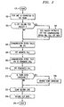
- FIG. 2 is a logic flow chart showing the steps of the process performed by the test facility.
-
- Referring to FIG. 1, a
test facility 100 is shown implementing a high speed service (such as XDSL or a high speed analog service) test for acommunication line 105 of a potential user.Communication line 105 is also connected at oneend 110 to customer premises equipment (CPE) 115 (CPE generally relates to any telephonic equipment such as telephones, key systems, PBX, answering machines, etc.) of the potential user. FIG. 1 also shows that thecommunication line 105 is connected to aswitch 120 located at acentral office 125. Theswitch 120 is any commercially available telecommunication switch which will allow thecentral office 125 to communicate to a plurality of CPEs. An example of aswitch 125 is a SESS telephonic switch produced by Lucent Technologies, Inc. - A second communication line, referred to as a
data line 130, is shown to connect theswitch 120, at thecentral office 125, to atest unit 135 and acommunication device 140, at aconnection point 145 of thedata line 130, located at thetest facility 100. A communication link is established between thetest facility 100 and theCPE 115 viadata line 130,communication line 105, andswitch 120. The combination of the electrical paths from theconnection point 145 ofdata line 130 to theend 110 of thecommunication line 105 through theswitch 120 establish the communication link. Additionally, theconnection point 145 of thedata line 130 is herein referred to as thefirst end 145 of the communication link and theend 110 of thecommunication line 105 is referred to as thesecond end 110 of the communication link. - Additional CPEs (150 and 155) are shown connected to the
switch 120 throughcommunication lines 160 arid 165 respectively. The invention will work equally well for a plurality of CPEs and communication lines without limitation as theswitch 120 is enabled to communicate with multiple CPEs. - The
communication line 105 is preferably a standard telephone line such as a single twisted pair line. However, it is appreciated that other non-standard telephone lines such as non-twisted pair, multiple twisted pair, coaxial, fiber optic, microwave or millimeter lines may suitably be employed. - The
communication line 105 is controlled by acentral office 125. A service provider associated with the telephoniccentral office 125 owns, maintains and controls thecommunication lines switch 120. Thecentral office 125 has full access to thecommunication line 105 and performs metallic loop access testing on thecommunication line 105. - The
central office 125 of FIG. 1 is shown with a mechanized loop testing (MLT) 170 block and theswitch 120 block. The MLT 170 block represents the MLT testing units at thecentral office 125. TheMLT units 170 are physically connected to thecommunication line 105 through theswitch 120. - The
test facility 100, FIG. 1, is shown to posses thetest unit 135 and thecommunication device 140 connected to thedata line 130 via thefirst end 145 of the communication link. Thedata line 130 is preferably a T-1 trunk line. A trunk is a communication line between two switching systems such as equipment in thecentral office 125 and thetest facility 100. The T-1 line is preferably a dual twisted pair digital transmission link with a transmission capacity of 1,544,000 bits per second. - Although a T-1 type line may be employed, the
data line 130 may selectively be any high speed digital line that is compatible with thecentral office 125 such as primary rate interface (PRI). PRI is the integrated service digital network (ISDN) equivalent of a T-1 line. Additionally, thedata line 130 may selectively also be a whole network or part of network which includes several switches and/or different types of transmission equipment. A non-digital line may also be employed as adata line 130. For an analog type line, the electrical properties inherent in all analog trunks will be employed. - As an example of operation,
communication device 140 located at thetest facility 100 either initiates or receives a call from theCPE 115. If the user of theCPE 115 wishes to know if thecommunication line 105 is capable of supporting high speed service then thetest facility 100 connects thetest unit 135 to thedata line 130 and the communication device 140 (either automatically or in response to user interaction) instructs theCPE 115 to terminate the call (such as hanging up a telephone). Once theCPE 115 terminates the call, thetest facility 100 begins the high speed testing with thetest unit 135. - The high speed service testing preferably takes place within a pre-selected time interval such as a ten second time interval after the
CPE 115 terminates the call. In the United States, called telephone lines stay active and connected for approximately ten seconds after a telephone is hung up (before the switch network at thecentral office 125 disconnects the call.) The specification for the time interval is described in Bellcore specification GR-505-CORE section 5.4.1.3 R5-22 [214]. - While testing, the
test unit 135 propagates electromagnetic energy waves (signals) from thefirst end 145 to thesecond end 110 of the communication link. When the waves reach thesecond end 110 of the communication link the waves are then reflected back to thetest unit 135 at thefirst end 145 of the communication link. Once the reflected waves are received by thetest unit 135, thetest unit 135 analyzes the reflected waves in relation to the propagated waves and determines the electrical properties of the communication link such as calculating the frequency properties of the loop. Thetest unit 135 calculates the channel capacity of the communication link divided in either asymmetrical and symmetrical upstream and downstream rates for the communication link. Thetest unit 135 then records the various electrical properties of the communication link for future use. It is appreciated that the recorded data from thetest unit 135 may selectively be stored in a memory unit located either within or external to thetest unit 135. - Additionally, if the communication link supports the use of a autocut function, the autocut function is preferably disabled by either the
test unit 135 or thecentral office 125 of FIG. 1. The autocut function is a function that prevents oscillations when theCPE 115 goes on-hook (i.e. theCPE 115 terminates the call). - The recorded data may selectively include the loop length, line load impedance, the presence of loading coils and analog frequency performance. The
test unit 135 also records whether the communication link supports a high speed service and the upstream and downstream rates of the communication link both for digital and/or analog transmission. Once this information is recorded thetest facility 100 determines if a high speed service may be supported which in a digital case supports XDSL and in an analog case selectively supports one or more of the following: television transmissions, music, voice, multiplexed voice, image and/or video transmission. - An example of the
test unit 135 is the Lucent Technologies, Inc. Remote Measurement System - Digital unit (RMS-D), however, other manufactures also produce similar units. These units are preferably digital signal processing (DSP) based and are selectively updated with new firmware to perform multiple tests. While there are several alternatives to measuring and calculating the electrical properties of the communication link the following two example tests selectively provide the test data to thetest unit 135. - First, a four wire return loss measurement is selectively used to determine the approximate length of the communication link loop when the
CPE 115 is on-hook. The larger the return signal (i.e. lower return loss) the shorter the loop length. The smaller the returned signal (i.e. higher return loss) the longer the loop length. - In the second test, a sweep of the frequency while looking at the returned signals is selectively used to determine the presence of loading coils. If this test indicates the presence of loading coils, the loading coils are selectively removed in a later operation.
- If the return loss of the first test is low, the loop is short and supports very high data rates. If the return loss of the first test is high, the loop is long and selectively supports high data rates. A mapping is selectively generated from the return loss results versus the data rates.
- The upstream or downstream asymmetric data rates for ADSL, ADSL Lite and VDSL are selectively mapped to the return loss values via correlation between the loop lengths and performance values as given in the XDSL standards. Similarly, the symmetric bit rates for HDSL, HDSL-2 and symmetric VDSL are selectively mapped to return loss values via correlation between loop lengths and the performance values given in the XDSL standards.
- Referring now to FIG. 2, a logic flow chart is shown describing the process of testing the communication link. The process starts at
step 175. Instep 180, thetest facility 100 of FIG. 1 connects thetest unit 135 to thedata line 130 at thefirst end 145. Next a call is made by either theCPE 115 or thecommunication device 140. Indecision step 185, FIG. 2, if theCPE 115 of FIG. 1 calls thetest facility 100, the process continues to step 190. Instep 190, FIG. 2, thecommunication device 140, FIG. 1, instructs theCPE 115 that thecommunication device 140 will call theCPE 115 back. The process then continues to step 195. If instead, thecommunication device 140 calls theCPE 115, the process continues directly to step 195. - In
step 195, FIG. 2, thecommunication device 140, FIG. 1, calls theCPE 115 which answers the call instep 200. Thecommunication device 140 then instructs theCPE 115, instep 205, to terminate the call, which theCPE 115 does instep 210. Thecommunication device 140 then determines indecision step 215 if there is echo canceling capabilities on the communication link. If there is echo canceling capabilities on the communication link,decision step 215 then sends the process to step 220 that disables the echo canceling capabilities of the communication link. The process then continues to step 225. Instep 225, FIG. 2, thetest facility 100, FIG. 1, begins testing the communication link with thetest unit 135. If there is no echo canceling on the communication link, the process then continues to step 225, FIG. 2, directly and thetest facility 100, FIG. 1, begins testing the communication link with thetest unit 135. - In
step 230, FIG. 2, the process then records any test data that thetest unit 135, FIG. 1, needs in order to determine performance of the communication link. Within this step, thetest unit 135 determines whether the communication link is high speed service capable and then, if capable of supporting high speed service, thetest unit 135 determines the upstream and downstream rates of the communication link. The process ends at 235. - While the specification in this invention is described in relation to certain implementations or embodiments, many details are set forth for the purpose of illustration.
Claims (35)
- A method for testing a communication link for high speed service comprising the steps of:CHARACTERIZED BY(a) coupling a test unit to the communication link at a first end of the communication link; and(b) calling a second end of the communication link, from the first end;(c) initiating testing, with the test unit, from the first end in response to termination of the call at the second end of the communication link within a time interval while the communication link stays active and connected after the second end of the communication link has terminated the call.
- The method according to claim 1 further including the step of recording test data.
- The method according to claim 2 wherein the step of recording includes the step of recording the loop length, line load impedance and the presence of loading coils.
- The method according to claim 2 wherein the step of recording further includes the steps of:determining support for high speed service on the communication link, anddetermining an upstream rate for the communication link.
- The method according to claim 4 wherein the upstream rate is symmetrical.
- The method according to claim 4 wherein the upstream rate is asymmetrical.
- The method according to claim 2 wherein the step of recording further includes the steps of:determining support for high speed service on the communication link, anddetermining a downstream rate for the communication link.
- The method according to claim 7 wherein the downstream rate is symmetrical.
- The method according to claim 7 wherein the downstream rate is asymmetrical.
- The method according to claim 1 wherein the step of testing includes propagating electromagnetic energy waves from the test unit at the first end of the communication link and receiving any reflected electromagnetic energy waves from the second end of the communication link.
- The method according to claim 1 wherein the communication link at the first end includes a trunk.
- The method according to claim 11 wherein the trunk is a digital line type.
- The method according to claim 12 wherein the trunk is either a T-1 or primary rate interface trunk.
- The method according to claim 11 wherein the trunk is a network.
- The method according to claim 11 wherein the trunk is part of a network.
- The method according to claim 11 wherein the trunk is a non-digital line type.
- The method according to claim 16 wherein the trunk has a maximum length and a plurality of electrical parameters of the trunk.
- The method according to claim 1 wherein the step of connecting the test unit includes connecting the test unit at a central office.
- The method according to claim 1, wherein the step of connecting the test unit includes connecting the test unit at a testing facility.
- The method according to claim 1 further including the step of determining if the communication link has echo canceling capabilities.
- The method according to claim 20 further including the step of disabling the echo canceling capabilities.
- The method according to claim 1, wherein the step of initiating testing within the time interval after the second end of the communication link has been terminated is performed before a central office disconnects the call.
- The method according to claim 1, wherein the high speed service is an asymmetrical digital subscriber line.
- The method according to claim 1, wherein the high speed service is an asymmetrical digital subscriber line lite.
- The method according to claim 1, wherein the high speed service is a high bit rate digital subscriber line.
- The method according to claim 1, wherein the high speed service is a high bit rate digital subscriber line-2.
- The method according to claim 1, wherein the high speed service is a symmetric digital subscriber line.
- The method according to claim 1, wherein the high speed service is a very high speed digital subscriber line service.
- The method according to claim 1, wherein the high speed data service is an analog high speed service including television transmission.
- The method according to claim 1, wherein the high speed data service is an analog high speed service including music transmission.
- The method according to claim 1, wherein the high speed data service is an analog high speed service including voice transmission.
- The method according to claim 1, wherein the high speed data service is an analog high speed service including multiplexed voice transmission.
- The method according to claim 1, wherein the high speed data service is an analog high speed service including image transmission.
- The method according to claim 1, wherein the high speed data service is an analog high speed service including video transmission.
- The method according to claim 1, wherein the time interval in the step of testing is approximately 10 seconds.
Applications Claiming Priority (2)
| Application Number | Priority Date | Filing Date | Title |
|---|---|---|---|
| US218970 | 1998-12-22 | ||
| US09/218,970 US6349130B1 (en) | 1998-12-22 | 1998-12-22 | Method to pre-qualify copper loops for ADSL service |
Publications (3)
| Publication Number | Publication Date |
|---|---|
| EP1014658A2 EP1014658A2 (en) | 2000-06-28 |
| EP1014658A3 EP1014658A3 (en) | 2002-05-08 |
| EP1014658B1 true EP1014658B1 (en) | 2004-10-20 |
Family
ID=22817243
Family Applications (1)
| Application Number | Title | Priority Date | Filing Date |
|---|---|---|---|
| EP99309849A Expired - Lifetime EP1014658B1 (en) | 1998-12-22 | 1999-12-07 | Method to pre-qualify copper loops for adsl service |
Country Status (6)
| Country | Link |
|---|---|
| US (1) | US6349130B1 (en) |
| EP (1) | EP1014658B1 (en) |
| JP (1) | JP3649979B2 (en) |
| KR (1) | KR100629096B1 (en) |
| CA (1) | CA2289342C (en) |
| DE (1) | DE69921282T2 (en) |
Families Citing this family (22)
| Publication number | Priority date | Publication date | Assignee | Title |
|---|---|---|---|---|
| US6895081B1 (en) * | 1999-04-20 | 2005-05-17 | Teradyne, Inc. | Predicting performance of telephone lines for data services |
| US6380971B1 (en) * | 1999-05-28 | 2002-04-30 | Qwest Communications International Inc. | VDSL video/data set top test equipment |
| GB2355361B (en) * | 1999-06-23 | 2004-04-14 | Teradyne Inc | Qualifying telephone lines for data transmission |
| US6687336B1 (en) * | 1999-09-30 | 2004-02-03 | Teradyne, Inc. | Line qualification with neural networks |
| US6466647B1 (en) * | 1999-11-17 | 2002-10-15 | Bellsouth Intellectual Property Corporation | System and method for estimating the capacity of a local loop to carry data |
| EP1111808A1 (en) * | 1999-12-21 | 2001-06-27 | Alcatel | Method and apparatus for determining properties of a transmission channel |
| GB0005227D0 (en) * | 2000-03-03 | 2000-04-26 | Teradyne Inc | Technique for estimatio of insertion loss |
| GB2365253B (en) * | 2000-07-19 | 2004-06-16 | Teradyne Inc | Method of performing insertion loss estimation |
| JP3570504B2 (en) * | 2000-08-30 | 2004-09-29 | 日本電気株式会社 | Condition monitoring method and device during subscriber line test |
| US6496566B1 (en) * | 2000-09-29 | 2002-12-17 | Lucent Technologies Inc. | Metallic testing of a subscriber loop that provides both voice and digital subscriber line services |
| JP2002118651A (en) | 2000-10-11 | 2002-04-19 | Nec Corp | METHOD FOR IMPROVING xDSL TRANSMISSION CHARACTERISTICS AND xDSL TRANSMISSION CHARACTERISTICS MEASURING SYSTEM |
| WO2002058369A2 (en) * | 2000-10-19 | 2002-07-25 | Teradyne, Inc. | Method and apparatus for bridged tap impact analysis |
| US6668041B2 (en) * | 2001-05-09 | 2003-12-23 | Centillium Communications, Inc. | Single ended line probing in DSL system |
| US6801601B2 (en) | 2000-10-31 | 2004-10-05 | Centillium Communications, Inc. | Single ended line probing in DSL system using transformerless hybrid |
| US6876725B2 (en) | 2001-05-09 | 2005-04-05 | Centillium Communications, Inc. | Single ended line probing in DSL system |
| US6748050B2 (en) * | 2001-05-22 | 2004-06-08 | General Instrument Corporation | Method and apparatus for performing either tone analysis on a local looped-back communications path or utilizing a hybrid reflection based looped-back test to test integrity |
| JP2003338878A (en) * | 2002-05-22 | 2003-11-28 | Nec Corp | Communication system, multiplexer included in the system, line transmission characteristic test method, and program |
| US6834099B1 (en) * | 2002-09-19 | 2004-12-21 | Sprint Communications Company L.P. | End-user communications test system |
| US6914961B2 (en) * | 2002-09-30 | 2005-07-05 | Teradyne, Inc. | Speed binning by neural network |
| US7620154B2 (en) * | 2002-12-23 | 2009-11-17 | Cambron G Keith | Equivalent working length determinative system for digital subscriber line circuits |
| US7386039B2 (en) * | 2003-09-26 | 2008-06-10 | Tollgrade Communications, Inc. | Method and apparatus for identifying faults in a broadband network |
| US8780933B2 (en) * | 2010-02-04 | 2014-07-15 | Hubbell Incorporated | Method and apparatus for automated subscriber-based TDM-IP conversion |
Family Cites Families (14)
| Publication number | Priority date | Publication date | Assignee | Title |
|---|---|---|---|---|
| DE3512787C1 (en) * | 1985-04-10 | 1986-08-21 | Telefonbau Und Normalzeit Gmbh, 6000 Frankfurt | Method for testing telephone sets, routes and parts of the control of telephone switching systems, in particular telephone private branch exchanges |
| US5111497A (en) * | 1990-09-17 | 1992-05-05 | Raychem Corporation | Alarm and test system for a digital added main line |
| US5353327A (en) * | 1992-05-04 | 1994-10-04 | At&T Bell Laboratories | Maintenance termination unit |
| US5465287A (en) * | 1994-01-13 | 1995-11-07 | Teledata Communication Ltd. | Subscriber line impedance measurement device and method |
| US5530724A (en) * | 1994-11-29 | 1996-06-25 | At&T Corp. | Echo canceler with automatic enablement/disablement on a per-call basis |
| JP2998624B2 (en) * | 1995-04-25 | 2000-01-11 | 日本電気株式会社 | Subscriber line impedance measurement method and measurement circuit |
| US5799060A (en) * | 1996-05-16 | 1998-08-25 | Harris Corporation | Multi-port caller ID-based telephone ringback test device |
| US5974115A (en) * | 1996-11-15 | 1999-10-26 | Bellsouth Intellectual Property Managment Corporation | System and method for testing subscriber lines and terminating equipment from a service platform |
| US6014425A (en) * | 1997-02-26 | 2000-01-11 | Paradyne Corporation | Apparatus and method for qualifying telephones and other attached equipment for optimum DSL operation |
| US5982851A (en) * | 1997-06-30 | 1999-11-09 | Harris Corporation | Call yourself BERT testing of ISDN line |
| US6002671A (en) * | 1997-09-03 | 1999-12-14 | Fluke Corporation | Test instrument for testing asymmetric digital subscriber lines |
| US5881130A (en) * | 1997-09-15 | 1999-03-09 | Teradyne, Inc. | Fast and noise-insensitive load status detection |
| US6091713A (en) * | 1998-04-13 | 2000-07-18 | Telcordia Technologies, Inc. | Method and system for estimating the ability of a subscriber loop to support broadband services |
| US6084946A (en) * | 1998-11-30 | 2000-07-04 | Bell Atlantic Network Services, Inc. | Qualifying a telephone line for digital transmission service |
-
1998
- 1998-12-22 US US09/218,970 patent/US6349130B1/en not_active Expired - Lifetime
-
1999
- 1999-11-10 CA CA002289342A patent/CA2289342C/en not_active Expired - Fee Related
- 1999-12-07 EP EP99309849A patent/EP1014658B1/en not_active Expired - Lifetime
- 1999-12-07 DE DE69921282T patent/DE69921282T2/en not_active Expired - Lifetime
- 1999-12-15 KR KR1019990057809A patent/KR100629096B1/en not_active Expired - Fee Related
- 1999-12-22 JP JP36359099A patent/JP3649979B2/en not_active Expired - Fee Related
Also Published As
| Publication number | Publication date |
|---|---|
| US6349130B1 (en) | 2002-02-19 |
| KR20000052478A (en) | 2000-08-25 |
| KR100629096B1 (en) | 2006-09-28 |
| JP3649979B2 (en) | 2005-05-18 |
| JP2000209338A (en) | 2000-07-28 |
| EP1014658A2 (en) | 2000-06-28 |
| DE69921282T2 (en) | 2005-11-03 |
| CA2289342A1 (en) | 2000-06-22 |
| CA2289342C (en) | 2004-10-19 |
| DE69921282D1 (en) | 2004-11-25 |
| EP1014658A3 (en) | 2002-05-08 |
Similar Documents
| Publication | Publication Date | Title |
|---|---|---|
| US6349130B1 (en) | Method to pre-qualify copper loops for ADSL service | |
| US6456694B1 (en) | Method for prequalifying subscriber lines for high speed data service | |
| KR0135508B1 (en) | How to access a customer premises device from a telephone exchange system and a data access device | |
| US6259676B1 (en) | Upgrading of subscriber connection | |
| US7289610B2 (en) | Digital subscriber line service over loaded loops | |
| US6741675B2 (en) | Method and apparatus for generating an audible tone in DSL environment | |
| US8208385B1 (en) | Method and apparatus for testing communications between a network edge device and a customer premises device | |
| US6163594A (en) | Call yourself BERT testing of ISDN line | |
| US5452343A (en) | Telemetry access arrangement | |
| US6111861A (en) | Method and system for managing high speed data communication | |
| US6154523A (en) | Method and system for linking a toll switch | |
| US6292540B1 (en) | Battery injection and loop supervision for DSL environment | |
| EP1021029B1 (en) | Telecommunication network with remotely controllable, line multi-interface and telecommunication method | |
| US20010036159A1 (en) | User selectable overlap and enbloc dialing of ISDN line | |
| US6762998B1 (en) | Access network system | |
| KR0135491B1 (en) | Telemetering access arrangement | |
| EP0881855A2 (en) | ISDN callback device for testing telephone line. | |
| CA2095668C (en) | Telemetry access arrangement | |
| Hawley et al. | Loop plant electronics: Voice frequency electronics for loop applications | |
| Musa | A fixed wireline network test for the broadband access evolution techology using VoDSL | |
| Dodds et al. | Simultaneous voice and Internet data on rural subscriber lines | |
| Techo | The Carrier Telephone Plant | |
| GB2354395A (en) | Telephone system | |
| HK1002640B (en) | Telemetry access arrangement | |
| HK1006939B (en) | Telemetry access arrangement |
Legal Events
| Date | Code | Title | Description |
|---|---|---|---|
| PUAI | Public reference made under article 153(3) epc to a published international application that has entered the european phase |
Free format text: ORIGINAL CODE: 0009012 |
|
| 17P | Request for examination filed |
Effective date: 19991221 |
|
| AK | Designated contracting states |
Kind code of ref document: A2 Designated state(s): AT BE CH CY DE DK ES FI FR GB GR IE IT LI LU MC NL PT SE |
|
| AX | Request for extension of the european patent |
Free format text: AL;LT;LV;MK;RO;SI |
|
| PUAL | Search report despatched |
Free format text: ORIGINAL CODE: 0009013 |
|
| AK | Designated contracting states |
Kind code of ref document: A3 Designated state(s): AT BE CH CY DE DK ES FI FR GB GR IE IT LI LU MC NL PT SE |
|
| AX | Request for extension of the european patent |
Free format text: AL;LT;LV;MK;RO;SI |
|
| AKX | Designation fees paid |
Designated state(s): DE FR GB |
|
| 17Q | First examination report despatched |
Effective date: 20030701 |
|
| GRAP | Despatch of communication of intention to grant a patent |
Free format text: ORIGINAL CODE: EPIDOSNIGR1 |
|
| GRAS | Grant fee paid |
Free format text: ORIGINAL CODE: EPIDOSNIGR3 |
|
| GRAA | (expected) grant |
Free format text: ORIGINAL CODE: 0009210 |
|
| AK | Designated contracting states |
Kind code of ref document: B1 Designated state(s): DE FR GB |
|
| REG | Reference to a national code |
Ref country code: GB Ref legal event code: FG4D |
|
| REG | Reference to a national code |
Ref country code: IE Ref legal event code: FG4D |
|
| REF | Corresponds to: |
Ref document number: 69921282 Country of ref document: DE Date of ref document: 20041125 Kind code of ref document: P |
|
| ET | Fr: translation filed | ||
| PLBE | No opposition filed within time limit |
Free format text: ORIGINAL CODE: 0009261 |
|
| STAA | Information on the status of an ep patent application or granted ep patent |
Free format text: STATUS: NO OPPOSITION FILED WITHIN TIME LIMIT |
|
| 26N | No opposition filed |
Effective date: 20050721 |
|
| REG | Reference to a national code |
Ref country code: GB Ref legal event code: 732E Free format text: REGISTERED BETWEEN 20131031 AND 20131106 |
|
| REG | Reference to a national code |
Ref country code: FR Ref legal event code: CD Owner name: ALCATEL-LUCENT USA INC. Effective date: 20131122 |
|
| REG | Reference to a national code |
Ref country code: FR Ref legal event code: GC Effective date: 20140410 |
|
| REG | Reference to a national code |
Ref country code: FR Ref legal event code: RG Effective date: 20141015 |
|
| REG | Reference to a national code |
Ref country code: FR Ref legal event code: PLFP Year of fee payment: 17 |
|
| REG | Reference to a national code |
Ref country code: FR Ref legal event code: PLFP Year of fee payment: 18 |
|
| PGFP | Annual fee paid to national office [announced via postgrant information from national office to epo] |
Ref country code: FR Payment date: 20161222 Year of fee payment: 18 |
|
| PGFP | Annual fee paid to national office [announced via postgrant information from national office to epo] |
Ref country code: DE Payment date: 20171211 Year of fee payment: 19 |
|
| PGFP | Annual fee paid to national office [announced via postgrant information from national office to epo] |
Ref country code: GB Payment date: 20171221 Year of fee payment: 19 |
|
| REG | Reference to a national code |
Ref country code: FR Ref legal event code: ST Effective date: 20180831 |
|
| PG25 | Lapsed in a contracting state [announced via postgrant information from national office to epo] |
Ref country code: FR Free format text: LAPSE BECAUSE OF NON-PAYMENT OF DUE FEES Effective date: 20180102 |
|
| REG | Reference to a national code |
Ref country code: GB Ref legal event code: 732E Free format text: REGISTERED BETWEEN 20190131 AND 20190206 |
|
| REG | Reference to a national code |
Ref country code: DE Ref legal event code: R081 Ref document number: 69921282 Country of ref document: DE Owner name: PROVENANCE ASSET GROUP LLC, PITTSFORD, US Free format text: FORMER OWNER: LUCENT TECHNOLOGIES INC., MURRAY HILL, N.J., US |
|
| REG | Reference to a national code |
Ref country code: DE Ref legal event code: R081 Ref document number: 69921282 Country of ref document: DE Owner name: PROVENANCE ASSET GROUP LLC, PITTSFORD, US Free format text: FORMER OWNER: NOKIA OF AMERICA CORP. (N. D. GES. D. STAATES DELAWARE), MURRAY HILL, NJ, US Ref country code: DE Ref legal event code: R081 Ref document number: 69921282 Country of ref document: DE Owner name: PROVENANCE ASSET GROUP LLC, PITTSFORD, US Free format text: FORMER OWNER: ALCATEL-LUCENT USA INC. (N. D. GES. D. STAATES DELAWARE), MURRAY HILL, N.J., US |
|
| REG | Reference to a national code |
Ref country code: DE Ref legal event code: R119 Ref document number: 69921282 Country of ref document: DE |
|
| GBPC | Gb: european patent ceased through non-payment of renewal fee |
Effective date: 20181207 |
|
| PG25 | Lapsed in a contracting state [announced via postgrant information from national office to epo] |
Ref country code: DE Free format text: LAPSE BECAUSE OF NON-PAYMENT OF DUE FEES Effective date: 20190702 |
|
| PG25 | Lapsed in a contracting state [announced via postgrant information from national office to epo] |
Ref country code: GB Free format text: LAPSE BECAUSE OF NON-PAYMENT OF DUE FEES Effective date: 20181207 |