EP1014568B1 - Méthode et dispositif de détection d'un signal reçu comportant du bruit - Google Patents
Méthode et dispositif de détection d'un signal reçu comportant du bruit Download PDFInfo
- Publication number
- EP1014568B1 EP1014568B1 EP19990124796 EP99124796A EP1014568B1 EP 1014568 B1 EP1014568 B1 EP 1014568B1 EP 19990124796 EP19990124796 EP 19990124796 EP 99124796 A EP99124796 A EP 99124796A EP 1014568 B1 EP1014568 B1 EP 1014568B1
- Authority
- EP
- European Patent Office
- Prior art keywords
- signal
- output voltage
- voltage
- pass filter
- low
- Prior art date
- Legal status (The legal status is an assumption and is not a legal conclusion. Google has not performed a legal analysis and makes no representation as to the accuracy of the status listed.)
- Expired - Lifetime
Links
Images
Classifications
-
- H—ELECTRICITY
- H03—ELECTRONIC CIRCUITRY
- H03G—CONTROL OF AMPLIFICATION
- H03G3/00—Gain control in amplifiers or frequency changers without distortion of the input signal
- H03G3/20—Automatic control
- H03G3/30—Automatic control in amplifiers having semiconductor devices
- H03G3/3084—Automatic control in amplifiers having semiconductor devices in receivers or transmitters for electromagnetic waves other than radiowaves, e.g. lightwaves
Definitions
- the invention relates to a method and a device for detecting a faulty received signal in a rain sensor of a motor vehicle for determining the wetting of a windshield.
- a received signal to be detected has a high interference signal component in addition to the useful signal component.
- the useful signal component is necessary to separate the useful signal component from the interference signal component.
- a typical application are rain sensors for motor vehicles, which detect the degree of wetting of a windshield due to the intensity of a coupled into the windshield and decoupled from this light signal.
- the stray light component can be very high, both when using visible light and from infrared light, and in the event of an extinction, can amount to a multiple of the useful signal.
- German Published Patent Application DE 3336027 A1 discloses an optoelectronic receiver in which a modulated transmission signal is coupled into the glass pane and the output signal received at a photodiode is detected.
- the optoelectronic receiver has a series circuit connected to a voltage source of the photodiode and a device for generating a photodiode current proportional output voltage, in which receiver for the purpose of compensation of incident light incidence, a controllable current source and a current source in response to disturbance light controlling control member is provided.
- the control of the current source takes place in such a way that a change of the photodiode current caused by the disturbing light causes substantially no change of the output voltage and thus the disturbing-light signal is suppressed.
- the current amplifier requires an expensive operational amplifier with a high-impedance input of more than 100 M ⁇ and a high-impedance resistor of about 10 M ⁇ as a feedback resistor.
- This high-impedance value causes a high sensitivity of the circuit to environmental influences such as moisture or dirt.
- an additional transistor for external light compensation is necessary.
- the known circuit is therefore a total of consuming and expensive. Nevertheless, a stationary error in the external light suppression is maintained.
- the inventive method according to claim 1 or the device according to the invention according to claim 4 achieved the separation of the Nutzsignalanteils of the Störsignalanteil by a feedback loop that controls the output signal with a fixed time constant to a fixed reference voltage level.
- the pulse duration of a transmission signal coupled into the transmission medium is smaller than the time constant of the feedback circuit, so that low-frequency extraneous signals are compensated, but not the pulsed useful signal applied to the output.
- the inventive method and the device according to the invention have the advantage that no current amplifier with high-impedance resistors are required, whereby the circuit is robust against environmental influences.
- the overall structure is simple and inexpensive to implement and the control loop is easy to adjust for stability.
- the feedback circuit is implemented by a PI controller whose non-inverting input with a fixed supply voltage and whose inverting input is connected via a low-pass filter to the output of an impedance converter.
- the PI controller ensures a stationary accuracy in the suppression of extraneous light, since the output voltage is always controlled to a fixed reference voltage.
- the impedance converter a low-cost type with low input resistance can be used.
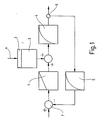
- FIG. 1 is a schematic block diagram of a preferred control circuit of the method according to the invention or of the device according to the invention.
- the light signal to be detected (arrow A) falls on the photodetector 2 and generates a luminous flux proportional to the light intensity. This causes at the P-member 3 a voltage drop, which in turn is proportional to the luminous flux.
- the output signals of the P-element 3 and a PI-controller 1 are added, as symbolized by the "+ symbols”.
- the output signal of the impedance converter 4 is applied to the output terminal 6 and is fed back via a low-pass filter 5 the PI controller 1 inverted.
- node 7 is a constant external signal setpoint (positive input), which is superimposed with a negative sign, the external signal actual value signal from the low-pass filter.
- the PI controller 1 controls its output so that the difference of the output voltage of the low-pass filter 5 and the external signal setpoint is compensated to zero, that is applied to the output of the PI controller, the same voltage as at the positive input of the node 7.
- Das means that the voltage applied to the output terminal 6 output voltage in the steady state constant and without is any external signal component. Due to the low-pass filter 5, however, the feedback control fails to correct short signals below the time constant of the low-pass filter 5. That is, short light signals A generate a proportional thereto voltage pulse at the output terminal 6, while low-frequency noise signals are compensated.
- useful signal pulses are thus generated with a duration which is smaller than the time constant of the low-pass filter 5, so that the Nutzsignalpulse not be corrected and changes the voltage applied to the output terminal 6 voltage changes the useful signal such as a change in the degree of wetting due to a rain shower or the like reflect.
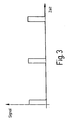
- a typical useful signal sequence is shown in FIG. Short light pulses of a duration of, for example, 100 ⁇ s are emitted at intervals of 1 ms.
- the shape, duration and frequency of the pulses can be adjusted by the skilled person according to the particular application.
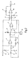
- FIG. 2 shows a circuit diagram of a device according to the invention for detecting a faulty received signal.
- the device for production the signal pulses as shown by way of example in Figure 3, is not shown.
- a known light-emitting diode can be used which operates, for example, in the visible or in the infrared range.
- the light signal to be detected falls on the photodetector 13 and generates at the resistor 14 a voltage proportional to the light intensity, which is impedance-converted by the impedance converter 12.
- the output of the impedance converter is connected via a low-pass filter 21, 22, 23 with the inverting input of a PI controller consisting of an operational amplifier 11 with feedback resistor 26 and feedback capacitor 27.
- the non-inverting input of the operational amplifier 11 is connected via a voltage divider 24, 25 to a supply voltage (triangular symbol), so that the non-inverting input of the PI controller 11 is always at a constant voltage, for example 2 volts.
- the PI controller controls its output to drive the resistor 14 so that the difference of the output voltage of the low-pass filter (negative input) and the external signal setpoint (positive input) is compensated to zero, that is applied to the output of the reference voltage 2 volts.
- At the output of the impedance converter 12 is then also the reference voltage in the regulated state of 2 volts.
- the amplifier 18, 19 eliminates by means of the input resistor 15 and the voltage divider 16, 17, the voltage offset of 2 volts and amplifies the useful signal, that is, the voltage applied to the output of the impedance converter 12 voltage difference to 2 volts by a constant factor, for example, factor 3
- the amplified useful signal is present at the output 20.
- a first terminal of a resistor 28 may be connected, the second terminal of which may be grounded or high impedance, for example by means of a microcontroller 30.
- the voltage changes at point 29 due to a change in the light incident on the photodiode 13 are less than when the resistor 28 is high impedance (or non-existent).
- the measuring range of the circuit is thereby increased, or reduced their sensitivity.
- the resistor 28 thus allows, for example, the adaptation of the detection device according to the invention on different tinted windows without changes to the circuit.
- the feedback loop has a fixed time constant due to the low-pass filter 21, 22, 23, which can be selected according to the respective field of use of the detector.
- Low-frequency (interfering) signals are compensated, while short signal pulses, such as the signal pulses shown schematically in Figure 3 substantially unattenuated at the output of the impedance converter 12 and then amplified by the amplifier 20 are supplied to the terminal.
- the inventive method and apparatus for detecting a noisy receive signal allows with a simple, inexpensive and stable circuit an effective noise suppression, in which stationary interference signals, such as constant sunlight on the windshield, are safely suppressed and not to override an input or Reinforcement stage lead. Overall, only inexpensive components are necessary; problematic, very high-impedance resistors are not required.
Claims (11)
- Procédé applicable à un capteur de pluie d'un véhicule automobile pour déterminer le mouillage d'un pare-brise selon lequel :- on injecte un signal d'émission comprenant un signal utile, pulsé, avec une durée d'impulsion fixe, dans un milieu de transmission,- on découple un signal de réception continu ayant une partie de signal utile et une partie de signal parasite, à partir du milieu de transmission, et- on convertit le signal de réception en une tension de sortie correspondante,caractérisé en ce que
le signal de réception génère une tension aux bornes d'une résistance, cette tension étant convertie par un convertisseur d'impédance (4, 12) en une tension de sortie,
la tension de sortie étant régulée par un circuit de réaction sur un niveau de tension de référence constant et
le circuit de réaction utilise un régulateur PI (1, 11, 26, 27) dont l'entrée non inversée reçoit une tension d'alimentation fixe et dont l'entrée inversée reçoit la tension de sortie par l'intermédiaire d'un filtre passe-bas (5, 21, 22, 33) et sa sortie est commandée pour piloter la résistance de façon que la différence entre la tension de sortie du filtre passe-bas et la tension d'alimentation soit régulée sur zéro et
le filtre passe-bas a une constante de temps supérieure à la durée impulsionnelle du signal utile de façon que la composante de la tension de sortie correspondant à la composante de signal utile n'influence pas la régulation du niveau de tension de référence. - Procédé selon la revendication 1,
caractérisé en ce que
la durée impulsionnelle du signal d'émission est d'environ 100 µs, la durée de la période du signal d'émission est d'environ 1000 µs et la constante de temps de la régulation est d'environ 3 µs. - Procédé selon la revendication 1 ou 2,
caractérisé en ce que
le milieu de transmission est en verre et le signal d'émission et le signal de réception sont des signaux lumineux. - Dispositif pour un capteur de pluie d'un véhicule pour déterminer le mouillage d'un pare-brise, le dispositif comportant :- une installation d'émission pour injecter un signal d'émission pulsé avec une durée d'impulsion fixe dans un milieu de transmission,- une installation de réception (2, 13) pour recevoir un signal de réception continu ayant une partie de signal utile et une partie de signal parasite à partir du milieu de transmission,- une installation de conversion (4, 12) pour convertir le signal de réception en une tension de sortie correspondante,caractérisé en ce que
l'installation de conversion (4, 12) comporte un circuit de réaction pour réguler la tension de sortie sur un niveau de tension de référence constant, ce circuit de réaction ayant un régulateur PI (1, 11, 26, 27) dont l'entrée non inversée reçoit une tension d'alimentation fïxe et dont l'entrée inversée reçoit par l'intermédiaire d'un filtre passe-bas (5, 21, 22, 23) la tension de sortie de l'installation de conversion (4, 12),
le régulateur PI (1, 11, 26, 27) étant relié par sa sortie, par l'intermédiaire d'une résistance (14) reliée à l'installation de réception, à l'entrée de l'installation de conversion (4, 12),
la durée impulsionnelle du signal utile étant inférieure à une constante de temps du filtre passe-bas (5, 21, 22, 23) du circuit de réaction (1, 5, 11, 21, 22, 23, 26, 27) de façon que la composante de la tension de sortie correspondant à la composante de signal utile n'influence pas la régulation du niveau de tension de référence. - Dispositif selon la revendication 4,
caractérisé en ce que
la constante de temps RC du filtre passe-bas est comprise entre 3 et 5 ms. - Dispositif selon l'une des revendications 4 et 5,
caractérisé en ce que
l'installation d'émission est une photodiode travaillant dans le domaine visible ou dans le domaine infrarouge IR. - Dispositif selon l'une des revendications 4 à 6,
caractérisé en ce que
l'installation de réception (2, 13) est un photocapteur. - Dispositif selon l'une des revendications 4 à 7,
caractérisé en ce que
l'installation de conversion (4, 12) est un convertisseur d'impédance. - Dispositif selon la revendication 8,
caractérisé en ce que
le convertisseur d'impédance est un amplificateur opérationnel avec une amplification prédéfinie. - Dispositif selon l'une des revendications 4 à 9,
caractérisé par
des moyens (28, 30) pour convertir la sensibilité du dispositif. - Capteur de pluie comportant un dispositif pour un capteur de pluie selon l'une des revendications 4 à 10 pour détecter le degré de mouillage d'un pare-brise de véhicule automobile.
Applications Claiming Priority (2)
| Application Number | Priority Date | Filing Date | Title |
|---|---|---|---|
| DE1998160214 DE19860214A1 (de) | 1998-12-24 | 1998-12-24 | Verfahren und Vorrichtung zur Erfassung eines störungsbehafteten Empfangssignals |
| DE19860214 | 1998-12-24 |
Publications (3)
| Publication Number | Publication Date |
|---|---|
| EP1014568A2 EP1014568A2 (fr) | 2000-06-28 |
| EP1014568A3 EP1014568A3 (fr) | 2001-02-28 |
| EP1014568B1 true EP1014568B1 (fr) | 2006-12-20 |
Family
ID=7892764
Family Applications (1)
| Application Number | Title | Priority Date | Filing Date |
|---|---|---|---|
| EP19990124796 Expired - Lifetime EP1014568B1 (fr) | 1998-12-24 | 1999-12-14 | Méthode et dispositif de détection d'un signal reçu comportant du bruit |
Country Status (3)
| Country | Link |
|---|---|
| EP (1) | EP1014568B1 (fr) |
| DE (2) | DE19860214A1 (fr) |
| ES (1) | ES2278431T3 (fr) |
Families Citing this family (1)
| Publication number | Priority date | Publication date | Assignee | Title |
|---|---|---|---|---|
| DE102007027071B4 (de) * | 2007-06-12 | 2019-09-12 | Bcs Automotive Interface Solutions Gmbh | Verfahren und Sensor zur Erfassung von Benetzungsereignissen auf einer Scheibe |
Family Cites Families (3)
| Publication number | Priority date | Publication date | Assignee | Title |
|---|---|---|---|---|
| DE4312590A1 (de) * | 1992-04-17 | 1993-10-28 | Peter Prof Dr Gottwald | Optoelektronische Einrichtung für Klarsichtscheiben zum Erkennen der Benetzung und Verschmutzungen und zur automatischen Betätigung von Warn- und/oder Reinigungsanlagen |
| DE9309837U1 (de) * | 1993-07-02 | 1993-09-02 | Reime Gerd | Anordnung zum Messen oder Erkennen der Benetzung einer für eine bestimmte Strahlung durchlässigen Wand oder Platte |
| DE19621627C1 (de) * | 1996-05-30 | 1997-09-18 | Bosch Gmbh Robert | Vorrichtung zum Erfassen einer Benetzung einer Scheibe |
-
1998
- 1998-12-24 DE DE1998160214 patent/DE19860214A1/de not_active Withdrawn
-
1999
- 1999-12-14 DE DE59914071T patent/DE59914071D1/de not_active Expired - Lifetime
- 1999-12-14 ES ES99124796T patent/ES2278431T3/es not_active Expired - Lifetime
- 1999-12-14 EP EP19990124796 patent/EP1014568B1/fr not_active Expired - Lifetime
Also Published As
| Publication number | Publication date |
|---|---|
| EP1014568A3 (fr) | 2001-02-28 |
| EP1014568A2 (fr) | 2000-06-28 |
| DE19860214A1 (de) | 2000-07-13 |
| DE59914071D1 (de) | 2007-02-01 |
| ES2278431T3 (es) | 2007-08-01 |
Similar Documents
| Publication | Publication Date | Title |
|---|---|---|
| EP1012014B1 (fr) | Dispositif et procede pour le fonctionnement d'un detecteur de pluie | |
| DE4036407C2 (de) | Sensorsystem | |
| DE19902319B4 (de) | Streulichtbrandmelder | |
| DE102007005187A1 (de) | Verfahren und Vorrichtung zur Bestimmung einer Entfernung zu einem rückstrahlenden Objekt | |
| EP1121601B1 (fr) | Procede et circuit de traitement de signaux pour un detecteur de mouvement | |
| WO1991001234A1 (fr) | Detecteur d'impuretes pour vitres d'automobiles | |
| DE102012021830A1 (de) | Optoelektronische Detektionseinrichtung mit einstellbarer Biasspannung eines Avalanche-Photodetektors für ein Kraftfahrzeug, Kraftfahrzeug und entsprechendes Verfahren | |
| DE69936402T2 (de) | Feuchtigkeitssensor mit digitaler signalverarbeitungsfilterung | |
| DE19729103A1 (de) | Vorrichtung und Verfahren zum Betreiben eines Regensensors | |
| EP1014568B1 (fr) | Méthode et dispositif de détection d'un signal reçu comportant du bruit | |
| DE10256429A1 (de) | Verfahren und Anordnung zum Messen eines modulierten Lichtsignals | |
| EP0847345A1 (fr) | Dispositif de detection d'humidite sur une vitre | |
| DE4217390C2 (de) | Einrichtung zur Steuerung einer Scheibenwischanlage | |
| EP1466790B1 (fr) | Dispositif de capteur d'impact | |
| DE102014111952A1 (de) | Sensorvorrichtung zum Erfassen eines Umfelds eines Kraftfahrzeugs, Fahrerassistenzsystem, Kraftfahrzeug sowie Verfahren | |
| EP1017191B1 (fr) | Procédé de discrimination des signaux reçus en présence de perturbation | |
| DE2821792A1 (de) | Optoelektronische vorrichtung zur erkennung des reissens eines fadens, der sich linear im lichtbuendel der vorrichtung bewegt | |
| DE102007034606A1 (de) | System zum Erfassen optischer Signale mit einem Regensensor und Verfahren | |
| DE4028165C2 (fr) | ||
| DE3928584C2 (fr) | ||
| DE102005006402B3 (de) | Sensorvorrichtung und System | |
| DE10253511B4 (de) | Optoelektronische Vorrichtung | |
| EP0973013B1 (fr) | Capteur de déplacement | |
| DE10338060A1 (de) | Sensorvorrichtung für ein Fahrzeug mit wenigstens einem Lichtsensor | |
| DE4313992A1 (de) | Verfahren zur Abstandsmessung beim Einparken von Fahrzeugen und Vorrichtungen zur Durchführung der Verfahren |
Legal Events
| Date | Code | Title | Description |
|---|---|---|---|
| PUAI | Public reference made under article 153(3) epc to a published international application that has entered the european phase |
Free format text: ORIGINAL CODE: 0009012 |
|
| AK | Designated contracting states |
Kind code of ref document: A2 Designated state(s): DE ES FR GB IT |
|
| AX | Request for extension of the european patent |
Free format text: AL;LT;LV;MK;RO;SI |
|
| PUAL | Search report despatched |
Free format text: ORIGINAL CODE: 0009013 |
|
| AK | Designated contracting states |
Kind code of ref document: A3 Designated state(s): AT BE CH CY DE DK ES FI FR GB GR IE IT LI LU MC NL PT SE |
|
| AX | Request for extension of the european patent |
Free format text: AL;LT;LV;MK;RO;SI |
|
| 17P | Request for examination filed |
Effective date: 20010828 |
|
| AKX | Designation fees paid |
Free format text: DE ES FR GB IT |
|
| PUAL | Search report despatched |
Free format text: ORIGINAL CODE: 0009013 |
|
| AK | Designated contracting states |
Kind code of ref document: A3 Designated state(s): DE ES FR GB IT |
|
| 17Q | First examination report despatched |
Effective date: 20040823 |
|
| GRAP | Despatch of communication of intention to grant a patent |
Free format text: ORIGINAL CODE: EPIDOSNIGR1 |
|
| GRAS | Grant fee paid |
Free format text: ORIGINAL CODE: EPIDOSNIGR3 |
|
| GRAA | (expected) grant |
Free format text: ORIGINAL CODE: 0009210 |
|
| AK | Designated contracting states |
Kind code of ref document: B1 Designated state(s): DE ES FR GB IT |
|
| REG | Reference to a national code |
Ref country code: GB Ref legal event code: FG4D Free format text: NOT ENGLISH |
|
| REF | Corresponds to: |
Ref document number: 59914071 Country of ref document: DE Date of ref document: 20070201 Kind code of ref document: P |
|
| ET | Fr: translation filed | ||
| REG | Reference to a national code |
Ref country code: ES Ref legal event code: FG2A Ref document number: 2278431 Country of ref document: ES Kind code of ref document: T3 |
|
| PLBE | No opposition filed within time limit |
Free format text: ORIGINAL CODE: 0009261 |
|
| STAA | Information on the status of an ep patent application or granted ep patent |
Free format text: STATUS: NO OPPOSITION FILED WITHIN TIME LIMIT |
|
| 26N | No opposition filed |
Effective date: 20070921 |
|
| PGFP | Annual fee paid to national office [announced via postgrant information from national office to epo] |
Ref country code: ES Payment date: 20081219 Year of fee payment: 10 |
|
| PGFP | Annual fee paid to national office [announced via postgrant information from national office to epo] |
Ref country code: IT Payment date: 20081227 Year of fee payment: 10 |
|
| PGFP | Annual fee paid to national office [announced via postgrant information from national office to epo] |
Ref country code: GB Payment date: 20081219 Year of fee payment: 10 |
|
| GBPC | Gb: european patent ceased through non-payment of renewal fee |
Effective date: 20091214 |
|
| PG25 | Lapsed in a contracting state [announced via postgrant information from national office to epo] |
Ref country code: GB Free format text: LAPSE BECAUSE OF NON-PAYMENT OF DUE FEES Effective date: 20091214 |
|
| REG | Reference to a national code |
Ref country code: ES Ref legal event code: FD2A Effective date: 20110329 |
|
| PG25 | Lapsed in a contracting state [announced via postgrant information from national office to epo] |
Ref country code: IT Free format text: LAPSE BECAUSE OF NON-PAYMENT OF DUE FEES Effective date: 20091214 |
|
| PG25 | Lapsed in a contracting state [announced via postgrant information from national office to epo] |
Ref country code: ES Free format text: LAPSE BECAUSE OF NON-PAYMENT OF DUE FEES Effective date: 20110316 |
|
| PG25 | Lapsed in a contracting state [announced via postgrant information from national office to epo] |
Ref country code: ES Free format text: LAPSE BECAUSE OF NON-PAYMENT OF DUE FEES Effective date: 20091215 |
|
| REG | Reference to a national code |
Ref country code: FR Ref legal event code: PLFP Year of fee payment: 17 |
|
| PGFP | Annual fee paid to national office [announced via postgrant information from national office to epo] |
Ref country code: FR Payment date: 20151218 Year of fee payment: 17 |
|
| PGFP | Annual fee paid to national office [announced via postgrant information from national office to epo] |
Ref country code: DE Payment date: 20160224 Year of fee payment: 17 |
|
| REG | Reference to a national code |
Ref country code: DE Ref legal event code: R119 Ref document number: 59914071 Country of ref document: DE |
|
| REG | Reference to a national code |
Ref country code: FR Ref legal event code: ST Effective date: 20170831 |
|
| PG25 | Lapsed in a contracting state [announced via postgrant information from national office to epo] |
Ref country code: FR Free format text: LAPSE BECAUSE OF NON-PAYMENT OF DUE FEES Effective date: 20170102 |
|
| PG25 | Lapsed in a contracting state [announced via postgrant information from national office to epo] |
Ref country code: DE Free format text: LAPSE BECAUSE OF NON-PAYMENT OF DUE FEES Effective date: 20170701 |