EP1014481A1 - Antenna alignment method and device - Google Patents
Antenna alignment method and device Download PDFInfo
- Publication number
- EP1014481A1 EP1014481A1 EP99125145A EP99125145A EP1014481A1 EP 1014481 A1 EP1014481 A1 EP 1014481A1 EP 99125145 A EP99125145 A EP 99125145A EP 99125145 A EP99125145 A EP 99125145A EP 1014481 A1 EP1014481 A1 EP 1014481A1
- Authority
- EP
- European Patent Office
- Prior art keywords
- antenna
- signal
- quality
- image
- digital
- Prior art date
- Legal status (The legal status is an assumption and is not a legal conclusion. Google has not performed a legal analysis and makes no representation as to the accuracy of the status listed.)
- Granted
Links
- 238000000034 method Methods 0.000 title claims abstract description 45
- 239000003086 colorant Substances 0.000 claims description 5
- 238000001514 detection method Methods 0.000 claims description 3
- 238000005259 measurement Methods 0.000 description 6
- 230000003321 amplification Effects 0.000 description 3
- 238000003199 nucleic acid amplification method Methods 0.000 description 3
- LFZDEAVRTJKYAF-UHFFFAOYSA-L barium(2+) 2-[(2-hydroxynaphthalen-1-yl)diazenyl]naphthalene-1-sulfonate Chemical group [Ba+2].C1=CC=CC2=C(S([O-])(=O)=O)C(N=NC3=C4C=CC=CC4=CC=C3O)=CC=C21.C1=CC=CC2=C(S([O-])(=O)=O)C(N=NC3=C4C=CC=CC4=CC=C3O)=CC=C21 LFZDEAVRTJKYAF-UHFFFAOYSA-L 0.000 description 2
- 230000005540 biological transmission Effects 0.000 description 2
- 230000001143 conditioned effect Effects 0.000 description 1
- 238000009434 installation Methods 0.000 description 1
- 230000005236 sound signal Effects 0.000 description 1
- 238000002604 ultrasonography Methods 0.000 description 1
Images


Classifications
-
- H—ELECTRICITY
- H01—ELECTRIC ELEMENTS
- H01Q—ANTENNAS, i.e. RADIO AERIALS
- H01Q1/00—Details of, or arrangements associated with, antennas
- H01Q1/12—Supports; Mounting means
-
- H—ELECTRICITY
- H01—ELECTRIC ELEMENTS
- H01Q—ANTENNAS, i.e. RADIO AERIALS
- H01Q3/00—Arrangements for changing or varying the orientation or the shape of the directional pattern of the waves radiated from an antenna or antenna system
Definitions
- the present invention relates to a method and a device for aligning the direction of an antenna connected to a receiver for digital signals.
- Another solution to the said problem consists of using a signal indicator to show "signal-to-noise” (AGC, Automatic Gain Control), which is shown as a kind of rough adjustment via an indicator, after which BER was presented as a fine adjustment via another indicator.
- AGC Automatic Gain Control
- a dilemma of all the solutions for installing a satellite receiver today is that they do not offer a total solution for installing the receiver via a single signal indicator in one unified sequence from the receiver being unpacked to the antenna being aligned with the transmitting satellite.
- the present invention relates to a method and a device for aligning the direction of an antenna connected to a receiver for digital signals in accordance with the enclosed independent claims.
- the present invention specifies a method of aligning the direction of an antenna connected to a receiver for digital signals.
- the antenna is aligned at the digital signals using a unified sequence of directions that include at least two methods for measuring the quality of a digital signal and that indicates the quality via one and the same means of indication regarding directions for both methods.
- the first method measures that a digital signal is received, which is indicated on the said means, whereby the means having received the signal automatically switches to showing the quality of the digital signal using a second method.
- the first method is AGC (Automatic Gain Control) and the second method is BER (Bit Error Rate).
- the means of indication is a whole screen or occupies part of a screen.
- An alternative embodiment of the invention comprises that the means is part of a portable unit.
- the said scale comprise different colours in a field in the indicator, whereby the best signal quality is obtained when a specific colour occupies a specific field during the alignment of the antenna.
- an image is called-up during the directions to prompt a user to carry out a unified alignment of the antenna.
- the picture is partly transparent when an antenna alignment has been made so that a received digital channel appears whose digital signal contents are reproduced on the transparent part of the image.
- the present invention specifies a device to align an antenna connected to a receiver for digital signals.
- the device includes:
- the device includes embodiments in accordance with the non-independent claims in the procedure according to that above.
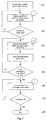
- Fig. 1 illustrates a flow scheme for aligning an antenna (in this case a parabolic dish) towards a transmitter according to the present invention.
- Block or step 100 in Fig. 1 shows that a user of a satellite receiver calls-up a special image on their TV receiver for adjusting their antenna, with which the user is guided through the whole adjustment procedure in a unified sequence, via at least two methods for measuring the signal quality, with one and the same means as well as with the same scale for indicating the quality of the signal.
- the user looks at the called-up page for antenna adjustment on the TV set. It is, however, not excluded that the user has a portable set with an indicator for signal quality according to the present invention, whereby the portable unit is remotely connected with the satellite receiver or TV set for acquiring signal quality information. It is even possible to obtain information via a cable between the portable unit and the other said units. Remote transmission takes place via well-known technology that is built on transmission of electromagnetic beams or ultrasound between connected units.
- FIG. 2-5 in connection with a run through of Fig. 1, whereby the designations 1-4 in Fig. 1 (within so-called balloons) refer to Figs. 2-5 respectively.
- step 110 in the adjustment procedure is taken if lock-on to the desired channel has not been achieved.
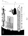
- channel position 3 Astra® MTV has been selected for adjusting the antenna with the satellite Astra®.
- a TV image 5 is acquired with the prompt to select 10 to "Select a predefined channel on ASTRA to be able to get a picture and check the signal strength", which is achieved with the signal quality indicator 20.
- indicator 20 constitutes part of a screen image (TV picture) 5, whereby it shows the signal quality or strength in AGC according to 110 in Fig. 1.
- the indicator is divided in to twenty fields, ten on either side of a distinct line in the middle 15.
- the colour in the field immediately to the right of yellow 14 is green 16, and the colour in the field to the right of the green is blue/green 18.
- the best signal quality that can be acquired with the indicator according to the invention is thus indicated when only field 19 shows the blue/green colour 18.
- AGC Automatic Gain Control
- signal amplification control is acquired though an AGC circuit that takes its power from either the IF (Intermediate Frequency) amplifier or the audio amplifier, i.e. IF-derived or Audio-derived amplification control respectively.
- IF Intermediate Frequency
- the AGC amplifier starts to decrease the amplification in the RF and IF steps in the electronics, whereby the level of the output audio signal in the loudspeakers is adjusted.
- a well-designed AGC system achieves a uniform level for audio output signals.
- the block or step 110 is maintained for alignment until the moment that the signal indication with AGC is acquired on indicator 20, which means that the antenna is "roughly” aligned with Astra® MTV from a digital point of view.
- step 100 in Fig. 1 shows that the indication on the signal indicator 20 is acquired at the same moment (directly) without any special alignment step being performed, step 120 comes into play and step 110 thereby becomes unnecessary, which is also the case after AGC signal indication in step 110.
- Step 120 in Fig. 1 is a condition box that describes the condition of the satellite receiver for deciding if the receiver has locked-on to a digital signal or not locked on to this. If the signal has been lost after step 110 has been performed, the receiver is conditioned to re-enter (NO) condition 110. If, however, the received digital signal is locked-on via AGC measurement, the receiver is switched to automatically begin measuring the signal quality with BER from the same indicator 20, see Fig. 3, which illustrates a television screen with BER signal quality indications in accordance with Fig. 1.
- BER Bit Error Rate
- Fig. 3 clarifies the signal quality in indicator 20 after the AGC measurement has been performed. It can be seen with the colour indications according to that above that the BER is still high because indicator 20 shows red colours 12 to the left in indicator 20 and blue/green 18 to the right. Better signal quality is acquired the further the blue/green colour 18 is located on the right. Ideally, this colour should only be found in field 19 for optimal quality according to the present embodiment of the invention.
- the indicator 20 acquires a colour scheme in accordance with Fig. 4, which shows another television screen 5 with BER signal quality measurement in accordance with Fig. 1.
- Fig. 4 shows the optimal signal quality for digital reception according to the present embodiment, which is seen in that only field 19 is blue/green 18, whereby the yellow colour 14 is essentially once again found in the centre of indicator 20 surrounded by red 12 to the left and green 16 to the right as seen by the viewer.
- the receiver is now placed in the condition according to step 140 in the flow scheme according to Fig. 1 where it self-tunes to the pre-programmed channel MTV. If the channel is found, conditional step 150, the TV image 22 appears, as is evident from Fig. 5, which illustrates a television screen with a BER signal quality indicator 20 where a digitally processed TV image 22 is acquired in accordance with Fig. 1, whereby the condition in step 160 of the flow scheme then becomes active.
- the user activates 170 the OK icon in Fig. 5 and the called-up image is switched off 180, whereby the tuned-in digital TV channel MTV appears and occupies the whole of the screen.
- the present invention also relates to a device for aligning an antenna connected to a receiver for digital signals.
- the device includes a means of indication 5, 20 for showing a unified sequence 10, 12-19 of directions when an antenna is aligned towards digital signals, and a means of detection in the receiver for detecting that a digital signal has been received by the receiver by measuring the quality of the signal according to a first method such as AGC. The quality is shown simultaneously on the means of indication 20.
- the device includes a means of switching for switching from the first method to a second method for measuring the quality of the signal, whereby the switching takes place when a signal has been detected with certainty and the means of indication switches to showing the quality of the signal according to a second method.
- a means of switching can be a program function that switches between, for example, two drive routines for a graphical reproduction of indicator 20 with scale 12-19 in AGC and BER.
- the actual alignment of the antenna with the digital signal is allowed using indications on a scale 12-19 via a single means of indication 20 in a unified sequence on the means of indication.
- the device allows embodiments in accordance with that specified in the method according to that stated above.
Landscapes
- Circuits Of Receivers In General (AREA)
- Variable-Direction Aerials And Aerial Arrays (AREA)
- Details Of Aerials (AREA)
- Waveguide Aerials (AREA)
- Testing, Inspecting, Measuring Of Stereoscopic Televisions And Televisions (AREA)
Abstract
Description
- The present invention relates to a method and a device for aligning the direction of an antenna connected to a receiver for digital signals.
- When a satellite receiver is installed, it is necessary to mount a parabolic antenna and align the microwave head arranged on the antenna so that signals from the transmitting satellite reach the said microwave head. To achieve this objective, external instruments or, alternatively, aids built into the satellite receiver must be used.
- The above aids work well when receiving analog signals, and it is sufficient to "follow the picture", i.e. to adjust the parabolic dish so that a weakly received analog signal gradually becomes a stronger, acceptable signal. This procedure does not function when receiving digital signals as the technology is built around "all or nothing", i.e. "1" or "0".
- Several years ago, Nokia® presented a new installation technology for digital satellite receivers with antenna adjustment. The technology in question is built around a signal indicator that displays bit errors (BER, Bit Error Rate) when a weak signal is received. When the BER then becomes better as the correct adjustment of the received signal is approached, the receiver begins to transfer pictures/sound. There nevertheless remain problems with this technology in that good measurement values do not exist a long way from the signal that is to be received, i.e. if the signal is not digital, bit errors do not exist.
- Another solution to the said problem consists of using a signal indicator to show "signal-to-noise" (AGC, Automatic Gain Control), which is shown as a kind of rough adjustment via an indicator, after which BER was presented as a fine adjustment via another indicator.
- A dilemma of all the solutions for installing a satellite receiver today is that they do not offer a total solution for installing the receiver via a single signal indicator in one unified sequence from the receiver being unpacked to the antenna being aligned with the transmitting satellite.
- The present invention relates to a method and a device for aligning the direction of an antenna connected to a receiver for digital signals in accordance with the enclosed independent claims.
- Specific embodiments of the invention are evident from the enclosed non-independent claims.
- To achieve the objective and solve the problems related to the area of technology, the present invention specifies a method of aligning the direction of an antenna connected to a receiver for digital signals. The antenna is aligned at the digital signals using a unified sequence of directions that include at least two methods for measuring the quality of a digital signal and that indicates the quality via one and the same means of indication regarding directions for both methods.
- The first method measures that a digital signal is received, which is indicated on the said means, whereby the means having received the signal automatically switches to showing the quality of the digital signal using a second method.
- In one embodiment of the invention, the first method is AGC (Automatic Gain Control) and the second method is BER (Bit Error Rate).
- In a further embodiment of the invention, the means of indication is a whole screen or occupies part of a screen.
- An alternative embodiment of the invention comprises that the means is part of a portable unit.
- In a specific embodiment, the said scale comprise different colours in a field in the indicator, whereby the best signal quality is obtained when a specific colour occupies a specific field during the alignment of the antenna.
- In yet a further embodiment, an image is called-up during the directions to prompt a user to carry out a unified alignment of the antenna. The picture is partly transparent when an antenna alignment has been made so that a received digital channel appears whose digital signal contents are reproduced on the transparent part of the image.
- In addition, the present invention specifies a device to align an antenna connected to a receiver for digital signals. The device includes:
- a means of indication for showing a common sequence of directions when an antenna is aligned towards digital signals;
- a means of detection to detect that a digital signal has been received by the receiver by measuring the quality of the signal according to a first method, whereby the quality is indicated on the means of indication;
- a means of switching to switch from the first method to a second method for measuring the quality of the signal, whereby the switch-over occurs when a signal has been detected with certainty and the means of indication begins toshow the quality of the signal according to a second method; and
- whereby the adjustment of the antenna towards a digital signal is allowed by directions via one single means of indication in a unified sequence on the means of indication.
-
- In addition, the device includes embodiments in accordance with the non-independent claims in the procedure according to that above.
- The continuation of the description refers to the enclosed figures for a better understanding of the present invention and its different embodiments, whereby
- Fig. 1 shows schematically a flow scheme for aligning an antenna towards a transmitter according to the present invention;
- Fig. 2 illustrates a television screen with an AGC signal quality indicator in accordance with Fig. 1;
- Fig. 3 illustrates a television screen with a BER signal quality indicator in accordance with Fig. 1;
- Fig. 4 illustrates another television screen with a BER signal quality indicator in accordance with Fig. 1; and
- Fig. 5 illustrates another television screen with a BER signal quality indicator where a digitally processed TV image has been acquired in accordance with Fig. 1.
-
- To clarify the present invention and its different embodiments, the description continues in the form of examples with satellite transmitters and satellite receivers for showing digital television with audio.
- Fig. 1 illustrates a flow scheme for aligning an antenna (in this case a parabolic dish) towards a transmitter according to the present invention.
- Block or
step 100 in Fig. 1 shows that a user of a satellite receiver calls-up a special image on their TV receiver for adjusting their antenna, with which the user is guided through the whole adjustment procedure in a unified sequence, via at least two methods for measuring the signal quality, with one and the same means as well as with the same scale for indicating the quality of the signal. - To adjust or align the antenna with the satellite, it is assumed that the user looks at the called-up page for antenna adjustment on the TV set. It is, however, not excluded that the user has a portable set with an indicator for signal quality according to the present invention, whereby the portable unit is remotely connected with the satellite receiver or TV set for acquiring signal quality information. It is even possible to obtain information via a cable between the portable unit and the other said units. Remote transmission takes place via well-known technology that is built on transmission of electromagnetic beams or ultrasound between connected units.
- In the continued description, reference is made to Figs. 2-5 in connection with a run through of Fig. 1, whereby the designations 1-4 in Fig. 1 (within so-called balloons) refer to Figs. 2-5 respectively.
- The
next step 110 in the adjustment procedure is taken if lock-on to the desired channel has not been achieved. In the example according to Fig. 2,channel position 3, Astra® MTV, has been selected for adjusting the antenna with the satellite Astra®. - As information for aligning the antenna according to Fig. 2, a
TV image 5 is acquired with the prompt to select 10 to "Select a predefined channel on ASTRA to be able to get a picture and check the signal strength", which is achieved with thesignal quality indicator 20. Here,indicator 20 constitutes part of a screen image (TV picture) 5, whereby it shows the signal quality or strength in AGC according to 110 in Fig. 1. The signal quality shown in Figs. 2-5 on theindicator 20, which is shown as a grey scale in the figures, nevertheless constitutes a colour scale in one embodiment of the invention where the colour on the left of the indicator is red 12 and in the middle, yellow 14. The indicator is divided in to twenty fields, ten on either side of a distinct line in themiddle 15. The colour in the field immediately to the right of yellow 14 is green 16, and the colour in the field to the right of the green is blue/green 18. The further the blue/green colour 18 moves to the right inindicator 20 towardsfield 19, the better the signal quality achieved. The best signal quality that can be acquired with the indicator according to the invention is thus indicated when onlyfield 19 shows the blue/green colour 18. - When a
colour - AGC (Automatic Gain Control), i.e. signal amplification control is acquired though an AGC circuit that takes its power from either the IF (Intermediate Frequency) amplifier or the audio amplifier, i.e. IF-derived or Audio-derived amplification control respectively. When an incoming signal increases in strength, the AGC amplifier starts to decrease the amplification in the RF and IF steps in the electronics, whereby the level of the output audio signal in the loudspeakers is adjusted. A well-designed AGC system achieves a uniform level for audio output signals.
- The block or
step 110 is maintained for alignment until the moment that the signal indication with AGC is acquired onindicator 20, which means that the antenna is "roughly" aligned with Astra® MTV from a digital point of view. - However, if
step 100 in Fig. 1 shows that the indication on thesignal indicator 20 is acquired at the same moment (directly) without any special alignment step being performed,step 120 comes into play andstep 110 thereby becomes unnecessary, which is also the case after AGC signal indication instep 110. -
Step 120 in Fig. 1 is a condition box that describes the condition of the satellite receiver for deciding if the receiver has locked-on to a digital signal or not locked on to this. If the signal has been lost afterstep 110 has been performed, the receiver is conditioned to re-enter (NO)condition 110. If, however, the received digital signal is locked-on via AGC measurement, the receiver is switched to automatically begin measuring the signal quality with BER from thesame indicator 20, see Fig. 3, which illustrates a television screen with BER signal quality indications in accordance with Fig. 1. - During digital transfer of signals, BER (Bit Error Rate) is a measurement of the quality of the signal. It is a measurement of the number of incorrectly detected bits that are detected in proportion to the total number of transferred bits expressed in percent.
- Fig. 3 clarifies the signal quality in
indicator 20 after the AGC measurement has been performed. It can be seen with the colour indications according to that above that the BER is still high becauseindicator 20 showsred colours 12 to the left inindicator 20 and blue/green 18 to the right. Better signal quality is acquired the further the blue/green colour 18 is located on the right. Ideally, this colour should only be found infield 19 for optimal quality according to the present embodiment of the invention. - During continued alignment of the antenna, the
indicator 20 acquires a colour scheme in accordance with Fig. 4, which shows anothertelevision screen 5 with BER signal quality measurement in accordance with Fig. 1. - Fig. 4 shows the optimal signal quality for digital reception according to the present embodiment, which is seen in that
only field 19 is blue/green 18, whereby theyellow colour 14 is essentially once again found in the centre ofindicator 20 surrounded by red 12 to the left and green 16 to the right as seen by the viewer. - The receiver is now placed in the condition according to step 140 in the flow scheme according to Fig. 1 where it self-tunes to the pre-programmed channel MTV. If the channel is found,
conditional step 150, theTV image 22 appears, as is evident from Fig. 5, which illustrates a television screen with a BERsignal quality indicator 20 where a digitally processedTV image 22 is acquired in accordance with Fig. 1, whereby the condition instep 160 of the flow scheme then becomes active. - To conclude the alignment of the antenna using the specially called-up
image 5, the user activates 170 the OK icon in Fig. 5 and the called-up image is switched off 180, whereby the tuned-in digital TV channel MTV appears and occupies the whole of the screen. - The blocks or steps in the flow scheme with the
conditions - The present invention also relates to a device for aligning an antenna connected to a receiver for digital signals. In one embodiment, the device includes a means of
indication unified sequence 10, 12-19 of directions when an antenna is aligned towards digital signals, and a means of detection in the receiver for detecting that a digital signal has been received by the receiver by measuring the quality of the signal according to a first method such as AGC. The quality is shown simultaneously on the means ofindication 20. - In addition, the device includes a means of switching for switching from the first method to a second method for measuring the quality of the signal, whereby the switching takes place when a signal has been detected with certainty and the means of indication switches to showing the quality of the signal according to a second method. Such a means of switching can be a program function that switches between, for example, two drive routines for a graphical reproduction of
indicator 20 with scale 12-19 in AGC and BER. - The actual alignment of the antenna with the digital signal is allowed using indications on a scale 12-19 via a single means of
indication 20 in a unified sequence on the means of indication. - The device allows embodiments in accordance with that specified in the method according to that stated above.
- The present invention is not limited to the embodiments described here. Instead, it is the drafting of the enclosed claims that specifies further possible embodiments for a person skilled within the area of technology.
Claims (14)
- Method for aligning the direction of an antenna connected to a receiver for digital signals characterised in that the antenna is aligned at the digital signals using a unified sequence of directions (12-19) that includes at least two methods (110, 130) for measuring the quality of a digital signal and that indicate the quality via one and the same means (20) with the same scale for the directions (12-19) with regard to both methods, whereby a first method (110) measures that a digital signal has been received, which is shown on the said means (20), and whereby the device (20), having received the signal, automatically switches to showing the quality of the digital signal by using a second method (130).
- Method according to claim 1 characterised in that the first method is AGC (Automatic Gain Control) and the second method is BER (Bit Error Rate).
- Method according to claim 1 or 2 characterised in that the means for giving directions (20) is a whole screen (5) or occupies part of a screen (5).
- Method according to claims 1-3 characterised in that the means (20) is a part of a portable unit.
- Method according to claims 1-4 characterised in that the scale comprises different colours (12, 14, 16, 18) in the fields in the indicator, whereby the best signal quality is obtained when a specific colour (18) occupies a specific field (19) during the alignment of the antenna.
- Method according to claims 1-5 characterised in that an image (5) is called-up during the directions that prompts a user to carry out a unified alignment of the antenna.
- Method according to claim 6 characterised in that the image (5) becomes partly transparent (22) when an antenna alignment has been made so that a received digital channel appears whose digital signal contents are reproduced on the transparent part of the image.
- Device for aligning the direction of an antenna connected to a receiver for digital signals characterised in that it includes:a means of indication (20) for showing a common sequence of directions (12-19) when an antenna is aligned towards digital signals;a means of detection to detect that a digital signal has been received by the receiver by measuring the quality of the signal according to a first method, whereby the quality is indicated on the means of indication (20);a means of switching to switch from the first method to the second method for measuring the quality of the signal, whereby the switch over occurs when a signal has been detected (120) with certainty and the means of indication (20) begins toshow the quality of the signal according to a second method (130); andwhereby the adjustment of the antenna towards a digital signal is allowed by indications via one single means of indication (20) in a unified sequence (12-19) on the means of indication.
- Device according to claim 8 characterised in that the first method is AGC (Automatic Gain Control) and the second method is BER (Bit Error Rate).
- Device according to claims 8 and 9 characterised in that the means (20) for giving directions is a whole screen (5) or occupies part of a screen.
- Device according to claims 8-10 characterised in that the device is a part of a portable unit.
- Device according to claims 8-11 characterised in that the scale comprises different colours (12, 14, 16, 18) in the fields in the indicator, whereby the best signal quality is obtained when a specific colour (18) occupies a specific field (19) during the alignment of the antenna.
- Device according to claims 8-12 characterised in that an image (5) is called-up during the directions that prompts a user to carry out a unified alignment of the antenna.
- Device according to claim 13 characterised in that the image (5) becomes partly transparent (22) when an antenna alignment has been made so that a received digital channel appears whose digital signal contents are reproduced on the transparent part of the image.
Applications Claiming Priority (2)
| Application Number | Priority Date | Filing Date | Title |
|---|---|---|---|
| SE9804352A SE9804352L (en) | 1998-12-16 | 1998-12-16 | Method and apparatus for aligning an antenna |
| SE9804352 | 1998-12-16 |
Publications (2)
| Publication Number | Publication Date |
|---|---|
| EP1014481A1 true EP1014481A1 (en) | 2000-06-28 |
| EP1014481B1 EP1014481B1 (en) | 2002-11-13 |
Family
ID=20413684
Family Applications (1)
| Application Number | Title | Priority Date | Filing Date |
|---|---|---|---|
| EP99125145A Expired - Lifetime EP1014481B1 (en) | 1998-12-16 | 1999-12-16 | Antenna alignment method and device |
Country Status (4)
| Country | Link |
|---|---|
| EP (1) | EP1014481B1 (en) |
| AT (1) | ATE227891T1 (en) |
| DE (1) | DE69903906T2 (en) |
| SE (1) | SE9804352L (en) |
Cited By (8)
| Publication number | Priority date | Publication date | Assignee | Title |
|---|---|---|---|---|
| WO2001022602A3 (en) * | 1999-09-21 | 2001-10-04 | Matsushita Electric Industrial Co Ltd | Digital broadcasting demodulation apparatus with a direction adjustment indicator for the receiving antenna |
| US6683581B2 (en) | 2000-12-29 | 2004-01-27 | Bellsouth Intellectual Property Corporation | Antenna alignment devices |
| US6789307B1 (en) | 2000-12-29 | 2004-09-14 | Bellsouth Intellectual Property Corporation | Methods for aligning an antenna with a satellite |
| US6906673B1 (en) | 2000-12-29 | 2005-06-14 | Bellsouth Intellectual Property Corporation | Methods for aligning an antenna with a satellite |
| US6937188B1 (en) * | 2001-11-13 | 2005-08-30 | Bellsouth Intellectual Property Corporation | Satellite antenna installation tool |
| EP1746683A1 (en) | 2005-07-18 | 2007-01-24 | Advanced Digital Broadcast S.A. | Signal receiver and method for aligning antenna for reception of at least two signals |
| CN105577903A (en) * | 2015-03-24 | 2016-05-11 | 宇龙计算机通信科技(深圳)有限公司 | A signal display method and mobile terminal |
| CN115211058A (en) * | 2020-01-27 | 2022-10-18 | 瑞典爱立信有限公司 | Apparatus and method for microwave radio transceiver control |
Citations (3)
| Publication number | Priority date | Publication date | Assignee | Title |
|---|---|---|---|---|
| EP0548844A2 (en) * | 1991-12-20 | 1993-06-30 | Sony Corporation | Satellite broadcasting reception system |
| US5463403A (en) * | 1992-07-10 | 1995-10-31 | General Instrument Corporation | Automatic adjustment of receiver apparatus based on channel-bit-error-rate-affected parameter measurement |
| EP0687029A1 (en) * | 1994-06-09 | 1995-12-13 | Thomson Consumer Electronics, Inc. | Apparatus and method for aligning a receiving antenna utilizing an audible tone |
-
1998
- 1998-12-16 SE SE9804352A patent/SE9804352L/en not_active IP Right Cessation
-
1999
- 1999-12-16 DE DE69903906T patent/DE69903906T2/en not_active Expired - Fee Related
- 1999-12-16 EP EP99125145A patent/EP1014481B1/en not_active Expired - Lifetime
- 1999-12-16 AT AT99125145T patent/ATE227891T1/en not_active IP Right Cessation
Patent Citations (3)
| Publication number | Priority date | Publication date | Assignee | Title |
|---|---|---|---|---|
| EP0548844A2 (en) * | 1991-12-20 | 1993-06-30 | Sony Corporation | Satellite broadcasting reception system |
| US5463403A (en) * | 1992-07-10 | 1995-10-31 | General Instrument Corporation | Automatic adjustment of receiver apparatus based on channel-bit-error-rate-affected parameter measurement |
| EP0687029A1 (en) * | 1994-06-09 | 1995-12-13 | Thomson Consumer Electronics, Inc. | Apparatus and method for aligning a receiving antenna utilizing an audible tone |
Cited By (15)
| Publication number | Priority date | Publication date | Assignee | Title |
|---|---|---|---|---|
| US6771318B1 (en) | 1999-09-21 | 2004-08-03 | Matsushita Electric Industrial Co., Ltd. | Digital broadcasting demodulation apparatus with a direction adjustment indicator for the receiving antenna |
| WO2001022602A3 (en) * | 1999-09-21 | 2001-10-04 | Matsushita Electric Industrial Co Ltd | Digital broadcasting demodulation apparatus with a direction adjustment indicator for the receiving antenna |
| US6889421B1 (en) | 2000-12-29 | 2005-05-10 | Bell South Intellectual Property Corp. | Antenna system installation and tuning method |
| US6789307B1 (en) | 2000-12-29 | 2004-09-14 | Bellsouth Intellectual Property Corporation | Methods for aligning an antenna with a satellite |
| US6795033B2 (en) | 2000-12-29 | 2004-09-21 | Bellsouth Intellectual Property Corporation | Antenna alignment devices |
| US6799364B2 (en) | 2000-12-29 | 2004-10-05 | Bellsouth Intellectual Property Corporation | Antenna aligning methods |
| US6683581B2 (en) | 2000-12-29 | 2004-01-27 | Bellsouth Intellectual Property Corporation | Antenna alignment devices |
| US6906673B1 (en) | 2000-12-29 | 2005-06-14 | Bellsouth Intellectual Property Corporation | Methods for aligning an antenna with a satellite |
| US7102580B2 (en) | 2000-12-29 | 2006-09-05 | Bellsouth Intellectual Property Corp. | Antenna alignment devices |
| US6937188B1 (en) * | 2001-11-13 | 2005-08-30 | Bellsouth Intellectual Property Corporation | Satellite antenna installation tool |
| EP1746683A1 (en) | 2005-07-18 | 2007-01-24 | Advanced Digital Broadcast S.A. | Signal receiver and method for aligning antenna for reception of at least two signals |
| CN105577903A (en) * | 2015-03-24 | 2016-05-11 | 宇龙计算机通信科技(深圳)有限公司 | A signal display method and mobile terminal |
| CN105577903B (en) * | 2015-03-24 | 2019-04-12 | 宇龙计算机通信科技(深圳)有限公司 | A kind of signal display method and mobile terminal |
| CN115211058A (en) * | 2020-01-27 | 2022-10-18 | 瑞典爱立信有限公司 | Apparatus and method for microwave radio transceiver control |
| US12615068B2 (en) | 2020-01-27 | 2026-04-28 | Telefonaktiebolaget Lm Ericsson (Publ) | Means and method for microwave radio transceiver control |
Also Published As
| Publication number | Publication date |
|---|---|
| ATE227891T1 (en) | 2002-11-15 |
| DE69903906D1 (en) | 2002-12-19 |
| SE9804352D0 (en) | 1998-12-16 |
| DE69903906T2 (en) | 2003-07-03 |
| SE512542C2 (en) | 2000-04-03 |
| SE9804352L (en) | 2000-04-03 |
| EP1014481B1 (en) | 2002-11-13 |
Similar Documents
| Publication | Publication Date | Title |
|---|---|---|
| EP0818923B1 (en) | Digital broadcast receiving device | |
| KR100367679B1 (en) | Receiving antenna alignment device and method using audible tones | |
| KR100343007B1 (en) | Antenna sorting apparatus and method using error condition of received signal | |
| US6661373B1 (en) | Antenna alignment meter | |
| US5283653A (en) | Dual HDTV/NTSC receiver using sequentially synthesized HDTV and NTSC co-channel carrier frequencies | |
| US6867819B2 (en) | Digital television receiver and antenna control method therein | |
| US7061542B1 (en) | Television receiving method and television receiver | |
| US5966638A (en) | Receiving apparatus, signal demodulating method, antenna apparatus, receiving system and antenna direction adjusting method | |
| EP1014481B1 (en) | Antenna alignment method and device | |
| US5436675A (en) | Television receiver with UHF/VHF and broadcast satellite tuners, power switch state display antenna reception level display, and external decoder output and input terminals | |
| US5329364A (en) | Method for reducing HRC mode reception time in cable television | |
| CA2113947C (en) | Television receiver | |
| KR100856343B1 (en) | Apparatus and method for optimizing levels of RF signals based on information stored in memory | |
| KR20030078883A (en) | Reception system for multiple-tuner television enabling to automatically connect each tuner to at least an antenna, whatever the number of antennae it comprises | |
| SE512542C3 (en) | Method and device for aligning an antenna | |
| US6744830B1 (en) | Digital broadcasting signal receiver | |
| US7185242B2 (en) | Digital display apparatus supporting error compensation and method thereof | |
| JP4701972B2 (en) | TV receiver | |
| EP1580833A1 (en) | Device and method for positioning of a dish antenna | |
| KR930003729B1 (en) | Automatic Detection Circuit and Method of Directional Distortion for Satellite Broadcasting Antenna | |
| US20070232229A1 (en) | Radio device | |
| CA1173557A (en) | Color television receiver with means for disabling vir correction during reproduction of recorded broadcast signals | |
| KR19980073248A (en) | Method and device for automatic control of satellite receiver antenna | |
| KR19980056074A (en) | Television receiver with alarm function for incorrect external device connection | |
| JPH05236382A (en) | Video receiving circuit of television receiver |
Legal Events
| Date | Code | Title | Description |
|---|---|---|---|
| PUAI | Public reference made under article 153(3) epc to a published international application that has entered the european phase |
Free format text: ORIGINAL CODE: 0009012 |
|
| AK | Designated contracting states |
Kind code of ref document: A1 Designated state(s): AT BE CH CY DE DK ES FI FR GB GR IE IT LI LU MC NL PT SE |
|
| AX | Request for extension of the european patent |
Free format text: AL;LT;LV;MK;RO;SI |
|
| 17P | Request for examination filed |
Effective date: 20000613 |
|
| RIN1 | Information on inventor provided before grant (corrected) |
Inventor name: LUNDSTROEM, OLLE Inventor name: FOGELSTOEM, GUNNAR |
|
| AKX | Designation fees paid |
Free format text: AT BE CH CY DE DK ES FI FR GB GR IE IT LI LU MC NL PT SE |
|
| 17Q | First examination report despatched |
Effective date: 20010213 |
|
| RAP1 | Party data changed (applicant data changed or rights of an application transferred) |
Owner name: NOKIA MULTIMEDIA TERMINALS OY |
|
| GRAG | Despatch of communication of intention to grant |
Free format text: ORIGINAL CODE: EPIDOS AGRA |
|
| RAP1 | Party data changed (applicant data changed or rights of an application transferred) |
Owner name: NOKIA CORPORATION |
|
| GRAG | Despatch of communication of intention to grant |
Free format text: ORIGINAL CODE: EPIDOS AGRA |
|
| GRAH | Despatch of communication of intention to grant a patent |
Free format text: ORIGINAL CODE: EPIDOS IGRA |
|
| GRAH | Despatch of communication of intention to grant a patent |
Free format text: ORIGINAL CODE: EPIDOS IGRA |
|
| GRAA | (expected) grant |
Free format text: ORIGINAL CODE: 0009210 |
|
| AK | Designated contracting states |
Kind code of ref document: B1 Designated state(s): AT BE CH CY DE DK ES FI FR GB GR IE IT LI LU MC NL PT SE |
|
| PG25 | Lapsed in a contracting state [announced via postgrant information from national office to epo] |
Ref country code: LI Free format text: LAPSE BECAUSE OF FAILURE TO SUBMIT A TRANSLATION OF THE DESCRIPTION OR TO PAY THE FEE WITHIN THE PRESCRIBED TIME-LIMIT Effective date: 20021113 Ref country code: GR Free format text: LAPSE BECAUSE OF FAILURE TO SUBMIT A TRANSLATION OF THE DESCRIPTION OR TO PAY THE FEE WITHIN THE PRESCRIBED TIME-LIMIT Effective date: 20021113 Ref country code: FI Free format text: LAPSE BECAUSE OF FAILURE TO SUBMIT A TRANSLATION OF THE DESCRIPTION OR TO PAY THE FEE WITHIN THE PRESCRIBED TIME-LIMIT Effective date: 20021113 Ref country code: CH Free format text: LAPSE BECAUSE OF FAILURE TO SUBMIT A TRANSLATION OF THE DESCRIPTION OR TO PAY THE FEE WITHIN THE PRESCRIBED TIME-LIMIT Effective date: 20021113 Ref country code: BE Free format text: LAPSE BECAUSE OF FAILURE TO SUBMIT A TRANSLATION OF THE DESCRIPTION OR TO PAY THE FEE WITHIN THE PRESCRIBED TIME-LIMIT Effective date: 20021113 Ref country code: AT Free format text: LAPSE BECAUSE OF FAILURE TO SUBMIT A TRANSLATION OF THE DESCRIPTION OR TO PAY THE FEE WITHIN THE PRESCRIBED TIME-LIMIT Effective date: 20021113 |
|
| REF | Corresponds to: |
Ref document number: 227891 Country of ref document: AT Date of ref document: 20021115 Kind code of ref document: T |
|
| REG | Reference to a national code |
Ref country code: GB Ref legal event code: FG4D |
|
| REG | Reference to a national code |
Ref country code: CH Ref legal event code: EP |
|
| REG | Reference to a national code |
Ref country code: IE Ref legal event code: FG4D |
|
| PG25 | Lapsed in a contracting state [announced via postgrant information from national office to epo] |
Ref country code: LU Free format text: LAPSE BECAUSE OF NON-PAYMENT OF DUE FEES Effective date: 20021216 Ref country code: IE Free format text: LAPSE BECAUSE OF NON-PAYMENT OF DUE FEES Effective date: 20021216 |
|
| REF | Corresponds to: |
Ref document number: 69903906 Country of ref document: DE Date of ref document: 20021219 |
|
| PG25 | Lapsed in a contracting state [announced via postgrant information from national office to epo] |
Ref country code: CY Free format text: LAPSE BECAUSE OF FAILURE TO SUBMIT A TRANSLATION OF THE DESCRIPTION OR TO PAY THE FEE WITHIN THE PRESCRIBED TIME-LIMIT Effective date: 20021231 |
|
| PG25 | Lapsed in a contracting state [announced via postgrant information from national office to epo] |
Ref country code: SE Free format text: LAPSE BECAUSE OF FAILURE TO SUBMIT A TRANSLATION OF THE DESCRIPTION OR TO PAY THE FEE WITHIN THE PRESCRIBED TIME-LIMIT Effective date: 20030213 Ref country code: PT Free format text: LAPSE BECAUSE OF FAILURE TO SUBMIT A TRANSLATION OF THE DESCRIPTION OR TO PAY THE FEE WITHIN THE PRESCRIBED TIME-LIMIT Effective date: 20030213 Ref country code: DK Free format text: LAPSE BECAUSE OF FAILURE TO SUBMIT A TRANSLATION OF THE DESCRIPTION OR TO PAY THE FEE WITHIN THE PRESCRIBED TIME-LIMIT Effective date: 20030213 |
|
| PG25 | Lapsed in a contracting state [announced via postgrant information from national office to epo] |
Ref country code: ES Free format text: LAPSE BECAUSE OF FAILURE TO SUBMIT A TRANSLATION OF THE DESCRIPTION OR TO PAY THE FEE WITHIN THE PRESCRIBED TIME-LIMIT Effective date: 20030529 |
|
| REG | Reference to a national code |
Ref country code: CH Ref legal event code: PL |
|
| ET | Fr: translation filed | ||
| PG25 | Lapsed in a contracting state [announced via postgrant information from national office to epo] |
Ref country code: MC Free format text: LAPSE BECAUSE OF NON-PAYMENT OF DUE FEES Effective date: 20030701 |
|
| PLBE | No opposition filed within time limit |
Free format text: ORIGINAL CODE: 0009261 |
|
| STAA | Information on the status of an ep patent application or granted ep patent |
Free format text: STATUS: NO OPPOSITION FILED WITHIN TIME LIMIT |
|
| REG | Reference to a national code |
Ref country code: IE Ref legal event code: MM4A |
|
| 26N | No opposition filed |
Effective date: 20030814 |
|
| PGFP | Annual fee paid to national office [announced via postgrant information from national office to epo] |
Ref country code: NL Payment date: 20071213 Year of fee payment: 9 |
|
| PGFP | Annual fee paid to national office [announced via postgrant information from national office to epo] |
Ref country code: IT Payment date: 20071220 Year of fee payment: 9 |
|
| PGFP | Annual fee paid to national office [announced via postgrant information from national office to epo] |
Ref country code: GB Payment date: 20071218 Year of fee payment: 9 |
|
| PGFP | Annual fee paid to national office [announced via postgrant information from national office to epo] |
Ref country code: DE Payment date: 20071221 Year of fee payment: 9 |
|
| PGFP | Annual fee paid to national office [announced via postgrant information from national office to epo] |
Ref country code: FR Payment date: 20071217 Year of fee payment: 9 |
|
| GBPC | Gb: european patent ceased through non-payment of renewal fee |
Effective date: 20081216 |
|
| NLV4 | Nl: lapsed or anulled due to non-payment of the annual fee |
Effective date: 20090701 |
|
| REG | Reference to a national code |
Ref country code: FR Ref legal event code: ST Effective date: 20090831 |
|
| PG25 | Lapsed in a contracting state [announced via postgrant information from national office to epo] |
Ref country code: DE Free format text: LAPSE BECAUSE OF NON-PAYMENT OF DUE FEES Effective date: 20090701 |
|
| PG25 | Lapsed in a contracting state [announced via postgrant information from national office to epo] |
Ref country code: NL Free format text: LAPSE BECAUSE OF NON-PAYMENT OF DUE FEES Effective date: 20090701 Ref country code: GB Free format text: LAPSE BECAUSE OF NON-PAYMENT OF DUE FEES Effective date: 20081216 |
|
| PG25 | Lapsed in a contracting state [announced via postgrant information from national office to epo] |
Ref country code: IT Free format text: LAPSE BECAUSE OF NON-PAYMENT OF DUE FEES Effective date: 20081216 |
|
| PG25 | Lapsed in a contracting state [announced via postgrant information from national office to epo] |
Ref country code: FR Free format text: LAPSE BECAUSE OF NON-PAYMENT OF DUE FEES Effective date: 20071231 |