EP1014405A2 - Push switch - Google Patents
Push switch Download PDFInfo
- Publication number
- EP1014405A2 EP1014405A2 EP99125555A EP99125555A EP1014405A2 EP 1014405 A2 EP1014405 A2 EP 1014405A2 EP 99125555 A EP99125555 A EP 99125555A EP 99125555 A EP99125555 A EP 99125555A EP 1014405 A2 EP1014405 A2 EP 1014405A2
- Authority
- EP
- European Patent Office
- Prior art keywords
- unit
- operation unit
- protrusion
- contact unit
- fixed contact
- Prior art date
- Legal status (The legal status is an assumption and is not a legal conclusion. Google has not performed a legal analysis and makes no representation as to the accuracy of the status listed.)
- Granted
Links
Images


Classifications
-
- H—ELECTRICITY
- H01—ELECTRIC ELEMENTS
- H01H—ELECTRIC SWITCHES; RELAYS; SELECTORS; EMERGENCY PROTECTIVE DEVICES
- H01H13/00—Switches having rectilinearly-movable operating part or parts adapted for pushing or pulling in one direction only, e.g. push-button switch
- H01H13/02—Details
- H01H13/12—Movable parts; Contacts mounted thereon
- H01H13/20—Driving mechanisms
-
- H—ELECTRICITY
- H01—ELECTRIC ELEMENTS
- H01H—ELECTRIC SWITCHES; RELAYS; SELECTORS; EMERGENCY PROTECTIVE DEVICES
- H01H2215/00—Tactile feedback
- H01H2215/002—Longer travel
-
- H—ELECTRICITY
- H01—ELECTRIC ELEMENTS
- H01H—ELECTRIC SWITCHES; RELAYS; SELECTORS; EMERGENCY PROTECTIVE DEVICES
- H01H2215/00—Tactile feedback
- H01H2215/004—Collapsible dome or bubble
- H01H2215/006—Only mechanical function
Definitions
- the present invention relates to a push switch used for various kinds of electronic apparatuses, and, more particularly, the invention relates to a small push switch having a long operation stroke.
- a switch disclosed in Japanese Patent Application Non-Examined Publication No. H8-203380 is widely known.
- the structure of the conventional push switch as an example is described referring to Fig. 5 which shows the cross sectional front view of the conventional switch, and to Fig. 6 which shows the exploded perspective view of the same.
- a resinous case 310 is formed to have a shape of a box having an opening at the upper side thereof.
- a short fixed contact unit 320 having a terminal 321 and a long contact unit 330 having a terminal 331 are disposed.
- a contact slip 340 is formed by bending a belt shaped elastic thin metal plate to have a shape like a character of U.
- the contact slip 340 has an upward bent portion 341 at one end thereof.
- the other end of the contact slip 340 is formed to have two leg portions 343 and 344.
- the two leg portions 343 and 344 are bent at the bent portions 342 as shown in Fig. 6.
- the two leg portions 343 and 344 have respective movable contact portions 345 and 346 at the respective ends thereof.
- a connecting portion 347 is formed for connecting the two leg portions 343 and 344.
- the movable contact portions 345 and 346 are disposed in the case 310 in such a manner as to touch the inner side of the bottom of the case 310.
- a resinous cover 350 is disposed on the upper side of the case 310 in such a manner as to close the upper side opening of the case 310. At one end of the cover 350 a downward protrusion is formed. A supporting portion 351, viz., the front end of the downward protrusion of the cover 350 presses downward the upward bent portion 341 of the contact slip 340, whereby the movable contact units 345 and 346 elastically contact to the inner side of the bottom of the case 310 with predetermined pressing force.
- a resinous operation unit 360 is disposed in such a manner as to extend from the space between the two leg portions 343 and 344 of the contact slip 340 to the outside of the cover 350 through a hole 352 formed through the central portion of the cover 350. That is, the operation unit 360 is supported to be movable up and down by the hole 352, and, the upper end portion 361 thereof protrudes though the hole 352.
- a pressing portion 362 formed on the outer side-wall of the operation unit 360 touches the upper side of the connecting portion 347 of the contact slip 340. The pressing portion 362 is pressed upward by the elastic force of the contact slip 340 and touches the lower side of the cover 350 as shown in Fig. 5.
- one movable contact portion 345 contacts to the long fixed contact unit 330, but the other movable contact portion 346 does not contact to neither of the contact units, accordingly the terminals 321 and 331 are not electrically connected.
- the pressing portion 362 presses the connecting portion 347 of the contact slip 340 downward, whereby the contact slip 340 rotates on the upward bent portion 341 supported by the supporting portion 351 of the cover 350, whereby the bent portion 342 bends further, also the movable contact portions 345 and 346 are elastically pressed and slide on the inner side of the bottom of the case 310, whereby the movable contact portion 346 comes to contact to the short fixed contact unit 320 in the state that the other movable contact portion 345 is in contact with the long fixed contact unit 330.
- the terminals 321 and 331 are electrically connected through these contact units.
- the operation unit 360 is pressed further downward until the lower end portion 363 of the operation unit 360 touches the inner side of the bottom of the case 310 as shown in Fig. 7 and stop the downward movement.
- the connecting portion 347 presses the pressing portion 362 of the operation unit 360 upward with the elastic restoring force of the contact slip 340, whereby the push switch comes back to the state as shown in fig. 5.
- the stroke of the push switch is constituted with a pre-stroke comprising the move of the operation unit 360 starting from the original state of Fig. 5 till the state that the terminals 321 and 331 are electrically connected by the contact between the movable contact portion 346 of the contact slip 340 and the short fixed contact unit 320, and, an over-stroke comprising the move of the operation unit 360 starting from the state of the above pre-stroke till the state that the lower end portion 363 of the operation unit 360 touches the inner side of the bottom of the case 1. Therefore, the total stroke is considerably long.
- the contact slip 340 is formed in such a manner that an elastic thin metal plate is bent to have a shape like a character of U having thin two leg portions 343 and 344. Therefore, careful attention have to be paid in handling during transport and assembling for preventing the intertwining and the deformation of the contact slip 340. Furthermore, the assembling of the switch is difficult and inefficient because the assembling is performed in such a manner that the contact slip 340 is set in the case 310 pressing the contact slip 340 with the supporting portion 351 of the downward protrusion of the cover 350 and the pressing portion 362 of the operation unit 360.
- the present invention addresses the above problems in the conventional push switch, and aims to provide a push switch in which the component parts are handled without difficulty, and assembling productivity is superior, also operation stroke is long.
- the push switch of the present invention comprises:
- Fig. 1 is a cross sectional front view showing a push switch in an exemplary embodiment in the present invention
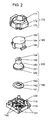
- Fig. 2 shows an exploded perspective view of the push switch in the same.
- a shallow cavity 111 is formed in the cavity 111.
- a central fixed contact unit 120 is disposed at the central position of the cavity 111, and two outer fixed contact units 130 are disposed symmetrically about the central fixed contact unit 120 at the positions outer than the central fixed contact unit 120.
- the contact units 120 and 130 are fixed to the substrate 110 by insert formation, and are exposed from the upper side of the switch substrate 110, also have substantially same height.
- contact terminals 121 and 131 are disposed on outer sides of the switch substrate 110.
- One terminal 121 is electrically connected to the central fixed contact unit 120, and the other terminal 131 is electrically connected to the outer fixed contact unit 130.
- a movable contact unit 140 formed with an elastic thin metal plate has a shape shown in Fig. 2. That is, the movable contact unit 140 comprises an outer annular portion 141, a tongue shaped portion 142 disposed at the central position of the outer annular portion 141. The tongue shaped portion 142 bends upward at a connecting portion 143 which connects the tongue shaped portion 142 to the outer annular portion 141.
- the outer annular portion 141 is placed on the outer fixed contact units 130.
- the tongue shaped portion 142 is disposed in such a manner as to face toward the central fixed contact unit 120 forming a predetermined insulation gap between the tongue shaped portion 142 and the central fixed contact unit 120.
- An elastic unit 150 formed with an elastic insulating material comprises a thin conical portion 151 which has an opening at the lower side thereof, an upward protrusion 153 which is formed on the upper side of the conical portion 151 and has predetermined dimensions, and a downward protrusion 156 which protrudes downward from the upper end of the opening of the conical portion 151 and has predetermined dimensions.
- a round cavity 155 having predetermined dimensions is formed, and at the lower end side of the downward protrusion 156, a round cavity 157 having predetermined dimensions is formed.
- the diameters and the depth of the cavities 155 and 157 are determined in such a manner that, when the elastic unit 150 is deformed by pressing downward the upper end side 154 of the upward protrusion 153, the thin conical portion 151 bends backward first, next the downward protrusion 156 compressibly deforms, last the upward protrusion 153 compressibly deforms.
- the lower end portion 152 of the conical portion 151 of the elastic unit 150 is placed on the outer annular portion 141 of the movable contact unit 140, and presses downward the outer annular portion 141 onto the outer fixed contact units 130.
- a resinous operation unit 160 is disposed on the upward protrusion 153 of the elastic unit 150.
- the upward protrusion 153 engages with a cavity 161 formed at the lower side of the operation unit 160.
- the flat surface of the upper end side 154 of the upward protrusion 153 touches the flat surface of the lower side of the upper portion of the operation unit 160.
- the operation unit 160 further comprises two protrusions 162 on the two different positions of the outer side-wall thereof and a protrusion 163 which protrudes outward from the lower end of the outer side-wall thereof.
- a resinous cover 170 On the inner side-wall of a resinous cover 170, two grooves corresponding to the two protrusions 162 of the operation unit 160 are formed, and a surrounding wall 172 having a cavity corresponding to the protrusion 163 are formed, at the respective corresponding positions.
- the two protrusions 162 of the operation unit 160 engage with the two grooves of the cover 170, and the protrusion 163 of the operation unit 160 engages with the cavity of the surrounding wall 172 of the cover 170.
- the cover 170 is fixed to the switch substrate 110 by caulking after inserting protrusions 112 formed on the periphery of the upper side of the switch substrate 110 into the cuttings 173 formed at the lower end periphery of the cover 170.
- the assembling of the push switch in this exemplary embodiment having the above structure is performed in such a manner that the component parts are placed on the switch substrate 110 in the order of the movable contact unit 140 first, next the elastic unit 150, then the operation unit 160, last the cover 170 and these are fixed by the above caulking. Therefore the assembling is simple and the respective component parts have shapes which hardly deform, whereby the handling of the component parts is not difficult, and automatic assembling can be realized without difficulty.
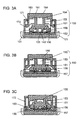
- Fig. 1 shows the state of switch-off.
- the operation unit 160 moves straight downward with the guidance of a hole 171 of the cover 170 and the inner side of the surrounding wall 172, whereby the flat lower side of the upper portion of the operation unit 160 presses downward the flat upper end side 154 of the upward protrusion 153 of the elastic unit 150.
- the thin conical portion 151 of the elastic unit 150 elastically deforms and bends backward, whereby the lower end side of the downward protrusion 156 of the elastic unit 150 presses downward the tongue shaped portion 142 of the movable contact unit 140, whereby the tongue shaped portion 142 contacts to the central fixed contact unit 120 disposed on the switch substrate 110, whereby the central contact unit 120 and the outer fixed contact units 130 (i.e., terminals 121 and 131) are electrically connected and comes to the state of switch-on as shown in Fig. 3A.
- the above operation constitutes a pre-stroke.
- the operation unit 160 When the operation unit 160 is further pressed, the operation unit 160 further moves downward, and the downward protrusion 156 elastically deforms as shown in Fig. 3B. Last, the upward protrusion 153 of the elastic unit 150 deforms as shown in Fig. 3C, and the operation unit 160 stops the downward movement when the protrusion 163 at the lower end periphery of the operation unit 160 touches upper side of the switch substrate 110.
- the occurrence of slippage between the operation unit 160 and the elastic unit 150 can be prevented because the upper portion of the elastic unit 150 engages with the cavity 161 formed at the lower side of the operation unit 160. Furthermore, the touching portions of both have flat surfaces, whereby the elastic unit 150 is pushed substantially vertically downward and elastically deforms without tilt.
- round cavities 155 and 157 are respectively formed on the upper end side 154 of the upward protrusion 153 and at the lower end side of the downward protrusion 156 of the elastic unit 150 for setting the predetermined resilient force and compressible dimension of the respective protrusions (153,156).
- the same effect can be obtained by replacing each of the cavities 155 and 157 with a cross-shaped cutting 181 which are symmetrical about the center thereof as shown in Fig. 4A, or a round cavity having two-cutting 182 as shown in Fig. 4B, or a round cavity having four-cutting 183 as shown in Fig. 4C.
- the same effect can be obtained by supporting the operation unit with the cover to be movable up and down without rotation by shaping the outer side-wall of the operation unit and either of the hole formed through the upper central portion of the cover or the inner side of the surrounding wall into non-round.
Landscapes
- Push-Button Switches (AREA)
Abstract
Description
- The present invention relates to a push switch used for various kinds of electronic apparatuses, and, more particularly, the invention relates to a small push switch having a long operation stroke.
- Conventionally, a switch disclosed in Japanese Patent Application Non-Examined Publication No. H8-203380 is widely known. Hereinafter, the structure of the conventional push switch as an example is described referring to Fig. 5 which shows the cross sectional front view of the conventional switch, and to Fig. 6 which shows the exploded perspective view of the same.
- In Fig. 5 and Fig. 6, a
resinous case 310 is formed to have a shape of a box having an opening at the upper side thereof. On the inner side of the bottom of thecase 310, a short fixedcontact unit 320 having aterminal 321 and along contact unit 330 having aterminal 331 are disposed. - A
contact slip 340 is formed by bending a belt shaped elastic thin metal plate to have a shape like a character of U. Thecontact slip 340 has an upwardbent portion 341 at one end thereof. The other end of thecontact slip 340 is formed to have twoleg portions leg portions bent portions 342 as shown in Fig. 6. The twoleg portions movable contact portions bent portion 342, a connectingportion 347 is formed for connecting the twoleg portions movable contact portions case 310 in such a manner as to touch the inner side of the bottom of thecase 310. - A
resinous cover 350 is disposed on the upper side of thecase 310 in such a manner as to close the upper side opening of thecase 310. At one end of the cover 350 a downward protrusion is formed. A supportingportion 351, viz., the front end of the downward protrusion of thecover 350 presses downward theupward bent portion 341 of thecontact slip 340, whereby themovable contact units case 310 with predetermined pressing force. - A
resinous operation unit 360 is disposed in such a manner as to extend from the space between the twoleg portions contact slip 340 to the outside of thecover 350 through ahole 352 formed through the central portion of thecover 350. That is, theoperation unit 360 is supported to be movable up and down by thehole 352, and, theupper end portion 361 thereof protrudes though thehole 352. Apressing portion 362 formed on the outer side-wall of theoperation unit 360 touches the upper side of the connectingportion 347 of thecontact slip 340. Thepressing portion 362 is pressed upward by the elastic force of thecontact slip 340 and touches the lower side of thecover 350 as shown in Fig. 5. - In the state shown in Fig. 5, one
movable contact portion 345 contacts to the long fixedcontact unit 330, but the othermovable contact portion 346 does not contact to neither of the contact units, accordingly theterminals - Hereinafter, the operation of the push switch having the above structure is described.
- When the
upper end portion 361 of theoperation unit 360 is pressed downward, thepressing portion 362 presses the connectingportion 347 of thecontact slip 340 downward, whereby thecontact slip 340 rotates on theupward bent portion 341 supported by the supportingportion 351 of thecover 350, whereby thebent portion 342 bends further, also themovable contact portions case 310, whereby themovable contact portion 346 comes to contact to the short fixedcontact unit 320 in the state that the othermovable contact portion 345 is in contact with the long fixedcontact unit 330. As a result, theterminals operation unit 360 is pressed further downward until thelower end portion 363 of theoperation unit 360 touches the inner side of the bottom of thecase 310 as shown in Fig. 7 and stop the downward movement. - After that, when the force pressing the
upper end portion 361 of theoperation unit 360 is removed, the connectingportion 347 presses thepressing portion 362 of theoperation unit 360 upward with the elastic restoring force of thecontact slip 340, whereby the push switch comes back to the state as shown in fig. 5. - In the above, the stroke of the push switch is constituted with a pre-stroke comprising the move of the
operation unit 360 starting from the original state of Fig. 5 till the state that theterminals movable contact portion 346 of thecontact slip 340 and the shortfixed contact unit 320, and, an over-stroke comprising the move of theoperation unit 360 starting from the state of the above pre-stroke till the state that thelower end portion 363 of theoperation unit 360 touches the inner side of the bottom of the case 1. Therefore, the total stroke is considerably long. - However, in the above conventional push switch, the
contact slip 340 is formed in such a manner that an elastic thin metal plate is bent to have a shape like a character of U having thin twoleg portions contact slip 340. Furthermore, the assembling of the switch is difficult and inefficient because the assembling is performed in such a manner that thecontact slip 340 is set in thecase 310 pressing thecontact slip 340 with the supportingportion 351 of the downward protrusion of thecover 350 and thepressing portion 362 of theoperation unit 360. - The present invention addresses the above problems in the conventional push switch, and aims to provide a push switch in which the component parts are handled without difficulty, and assembling productivity is superior, also operation stroke is long.
- For realizing the above aim, the push switch of the present invention comprises:
- (a) a switch substrate which has an outer fixed contact unit and a central fixed contact unit, both of which are fixed to the switch substrate and the contact portions of the respective fixed contact units are exposed from the upper side of the switch substrate, also has respective contact terminals extended outward from the respective fixed contact units,
- (b) a movable contact unit which is formed with an elastic thin metal plate, and has an outer annular portion placed on the outer fixed contact units, also has a tongue shaped portion which faces toward the central fixed contact unit forming a predetermined insulation gap between the tongue shaped portion and the central fixed contact unit,
- (c) an elastic unit which is formed with an elastic material, and has a conical portion having an opening at the lower side thereof, an upward protrusion and a downward protrusion which protrudes downward from the upper end of the opening, and, presses the outer annular portion of the movable contact unit with the lower end portion of the conical portion,
- (d) an operation unit which is disposed on the elastic unit in such a manner as to be movable up and down, and, has a protrusion at the lower end periphery thereof for preventing the slip off of the operation unit, and
- (e) a cover which is fixed to the periphery of the switch substrate, and
holds the operation unit with the surrounding wall thereof in such a manner
as to be movable up and down without the upward slip off of the operation
unit, also has a hole, through which the operation unit protrudes, at the upper
central portion thereof,
wherein, when the upper end portion of the operation unit is pressed, the conical portion of the elastic unit elastically deforms first, whereby the downward protrusion in the conical portion presses the tongue shaped portion of the movable contact unit, whereby the tongue shaped portion touches the central fixed contact unit, next at least one of the upward protrusion or the downward protrusion of the elastic unit deforms, whereby the protrusion formed at the lower end periphery of the operation unit touches the switch substrate. The above structure realizes a push switch in which component parts are handled without difficulty, and the assembling productivity is superior, also the operation stroke is long. -
-
- Fig. 1 shows a cross sectional front view of a push switch in an exemplary embodiment in the present invention,
- Fig. 2 shows an exploded perspective view of the push switch in the exemplary embodiment in the same,
- Fig. 3A, Fig. 3B and Fig. 3C are cross sectional front views showing the states of operations of the push switch in the exemplary embodiment in the same,
- Fig. 4A, Fig. 4B and Fig. 4C are perspective views showing the shapes of cavities and cuttings formed on the protrusions of the elastic unit of the push switch in the exemplary embodiment in the same,
- Fig. 5 shows a cross sectional front view of an example of conventional push switches,
- Fig. 6 shows an exploded perspective view of the same, and
- Fig. 7 is an cross sectional front view showing the state of an operation of the same.
-
- Hereinafter, an exemplary embodiment in the present invention is described referring to illustrations. Fig. 1 is a cross sectional front view showing a push switch in an exemplary embodiment in the present invention, and Fig. 2 shows an exploded perspective view of the push switch in the same.
- In Fig. 1 and Fig. 2, on the upper side of a resinous plate shaped
switch substrate 110, ashallow cavity 111 is formed. In thecavity 111, a centralfixed contact unit 120 is disposed at the central position of thecavity 111, and two outerfixed contact units 130 are disposed symmetrically about the centralfixed contact unit 120 at the positions outer than the centralfixed contact unit 120. Thecontact units substrate 110 by insert formation, and are exposed from the upper side of theswitch substrate 110, also have substantially same height. On outer sides of theswitch substrate 110,contact terminals terminal 121 is electrically connected to the centralfixed contact unit 120, and theother terminal 131 is electrically connected to the outerfixed contact unit 130. - A
movable contact unit 140 formed with an elastic thin metal plate has a shape shown in Fig. 2. That is, themovable contact unit 140 comprises an outerannular portion 141, a tongue shapedportion 142 disposed at the central position of the outerannular portion 141. The tongue shapedportion 142 bends upward at a connectingportion 143 which connects the tongue shapedportion 142 to the outerannular portion 141. - The outer
annular portion 141 is placed on the outer fixedcontact units 130. The tongue shapedportion 142 is disposed in such a manner as to face toward the central fixedcontact unit 120 forming a predetermined insulation gap between the tongue shapedportion 142 and the central fixedcontact unit 120. - An
elastic unit 150 formed with an elastic insulating material comprises a thinconical portion 151 which has an opening at the lower side thereof, anupward protrusion 153 which is formed on the upper side of theconical portion 151 and has predetermined dimensions, and adownward protrusion 156 which protrudes downward from the upper end of the opening of theconical portion 151 and has predetermined dimensions. On theupper end side 154 of theupward protrusion 153, around cavity 155 having predetermined dimensions is formed, and at the lower end side of thedownward protrusion 156, around cavity 157 having predetermined dimensions is formed. - The diameters and the depth of the
cavities elastic unit 150 is deformed by pressing downward theupper end side 154 of theupward protrusion 153, the thinconical portion 151 bends backward first, next thedownward protrusion 156 compressibly deforms, last theupward protrusion 153 compressibly deforms. - The
lower end portion 152 of theconical portion 151 of theelastic unit 150 is placed on the outerannular portion 141 of themovable contact unit 140, and presses downward the outerannular portion 141 onto the outer fixedcontact units 130. - On the
upward protrusion 153 of theelastic unit 150, aresinous operation unit 160 is disposed. Theupward protrusion 153 engages with acavity 161 formed at the lower side of theoperation unit 160. In this case, the flat surface of theupper end side 154 of theupward protrusion 153 touches the flat surface of the lower side of the upper portion of theoperation unit 160. - The
operation unit 160 further comprises twoprotrusions 162 on the two different positions of the outer side-wall thereof and aprotrusion 163 which protrudes outward from the lower end of the outer side-wall thereof. - On the inner side-wall of a
resinous cover 170, two grooves corresponding to the twoprotrusions 162 of theoperation unit 160 are formed, and asurrounding wall 172 having a cavity corresponding to theprotrusion 163 are formed, at the respective corresponding positions. The twoprotrusions 162 of theoperation unit 160 engage with the two grooves of thecover 170, and theprotrusion 163 of theoperation unit 160 engages with the cavity of the surroundingwall 172 of thecover 170. By engaging the outer side-wall of theoperation unit 160 with the inner side-wall of thecover 170 as described in the above, theoperation unit 160 is supported to be movable up and down without the rotation and without the upward slip off of theoperation unit 160. - The
cover 170 is fixed to theswitch substrate 110 by caulking after insertingprotrusions 112 formed on the periphery of the upper side of theswitch substrate 110 into thecuttings 173 formed at the lower end periphery of thecover 170. - The assembling of the push switch in this exemplary embodiment having the above structure is performed in such a manner that the component parts are placed on the
switch substrate 110 in the order of themovable contact unit 140 first, next theelastic unit 150, then theoperation unit 160, last thecover 170 and these are fixed by the above caulking. Therefore the assembling is simple and the respective component parts have shapes which hardly deform, whereby the handling of the component parts is not difficult, and automatic assembling can be realized without difficulty. - Hereinafter the operation of the push switch having the above structure is described.
- Fig. 1 shows the state of switch-off. When the
upper end side 164 of theoperation unit 160 is pressed downward, theoperation unit 160 moves straight downward with the guidance of ahole 171 of thecover 170 and the inner side of the surroundingwall 172, whereby the flat lower side of the upper portion of theoperation unit 160 presses downward the flatupper end side 154 of theupward protrusion 153 of theelastic unit 150. - By the above operation, the thin
conical portion 151 of theelastic unit 150 elastically deforms and bends backward, whereby the lower end side of thedownward protrusion 156 of theelastic unit 150 presses downward the tongue shapedportion 142 of themovable contact unit 140, whereby the tongue shapedportion 142 contacts to the central fixedcontact unit 120 disposed on theswitch substrate 110, whereby thecentral contact unit 120 and the outer fixed contact units 130 (i.e.,terminals 121 and 131) are electrically connected and comes to the state of switch-on as shown in Fig. 3A. - The above operation constitutes a pre-stroke.
- When the
operation unit 160 is further pressed, theoperation unit 160 further moves downward, and thedownward protrusion 156 elastically deforms as shown in Fig. 3B. Last, theupward protrusion 153 of theelastic unit 150 deforms as shown in Fig. 3C, and theoperation unit 160 stops the downward movement when theprotrusion 163 at the lower end periphery of theoperation unit 160 touches upper side of theswitch substrate 110. - The operation from the state of Fig. 3A to the state of Fig. 3C constitutes an over-stroke.
- In the above pressing operation, the occurrence of slippage between the
operation unit 160 and theelastic unit 150 can be prevented because the upper portion of theelastic unit 150 engages with thecavity 161 formed at the lower side of theoperation unit 160. Furthermore, the touching portions of both have flat surfaces, whereby theelastic unit 150 is pushed substantially vertically downward and elastically deforms without tilt. - After that, when the force pressing the
operation unit 160 is removed, theelastic unit 150 and themovable contact unit 140 come back to the state of Fig. 1 (i.e., state of switch-off) by the elastic restoring force of theelastic unit 150. - In the above description,
round cavities upper end side 154 of theupward protrusion 153 and at the lower end side of thedownward protrusion 156 of theelastic unit 150 for setting the predetermined resilient force and compressible dimension of the respective protrusions (153,156). However, the same effect can be obtained by replacing each of thecavities - Also, the same effect can be obtained by supporting the operation unit with the cover to be movable up and down without rotation by shaping the outer side-wall of the operation unit and either of the hole formed through the upper central portion of the cover or the inner side of the surrounding wall into non-round.
- In this exemplary embodiment, the following advantageous effects are obtainable.
- (1) A push switch, in which the component parts thereof can be handled without difficulty, and assembling productivity is superior, also an operation stroke comprising a pre-stroke and an over-stroke is long, can be realized.
- (2) In a push switch constituted in such a manner that, when the upper side of the operation unit is pressed, the thin conical portion of the elastic unit elastically deforms first, whereby the downward protrusion in the conical portion presses the tongue shaped portion of the movable contact unit, whereby the tongue shaped portion touches the central fixed contact unit, next the downward protrusion elastically deforms by a predetermined dimension, last the upward protrusion elastically deforms, more stable operation is realized in addition to the above effect.
- (3) In a push switch constituted in such a manner that the setting of predetermined resilient force and compressible dimension are set by forming the cavity having predetermined size and depth or the cutting which is symmetrical about the center thereof having predetermined size and depth on at least either of the upward protrusion or the downward protrusion of the elastic unit, the setting of the resilient force in the over-stroke and the length of the over-stroke can be set at desired values without difficulty.
- (4) In a push switch constituted in such a manner that, the flat upper end side of the upward protrusion of the elastic unit touches the flat lower side of the operation unit, and the protrusion formed on one side engages with the cavity formed on the other side, the positioning between the lower side of the operation unit and the upper end side of the upward protrusion of the elastic unit becomes stable and the slippage between both in the occasion of the pressing operation of the operation unit can be prevented, whereby the elastic unit can surely be elastically deformed.
- (5) In a push switch constituted in such a manner that the outer side-wall of the operation unit and either of the hole formed through the upper central portion of the cover or the inner side of the surrounding wall are shaped into non-round, and the operation unit is supported by the cover to be movable up and down without rotation, the operation unit is guided to maintain a constant facing direction without rotation during up and down movement, whereby the elastic unit can be elastically deformed without tilt, which enables surer switching operation.
- (6) In a push switch constituted in such a manner that the outer fixed contact units and the inner fixed contact unit are exposed from the upper side of the switch substrate and have substantially same height, and the tongue shaped portion disposed at the central position of the movable contact unit is bent upward at the connecting portion, which connects the tongue shaped portion to the outer annular portion, for forming a predetermined insulation gap between the tongue shaped portion and the central fixed contact unit, the insulation gap between the central fixed contact unit and the tongue shaped portion can be surely maintained, also the movable contact unit hardly deforms as a whole even when the tongue shaped portion of the movable contact unit is strongly pressed because the movable contact unit becomes only flat even under strong pressing force, whereby the electric characteristic of the push switch becomes stable.
-
Claims (13)
- A push switch comprising:(a) a switch substrate (110) having an outer fixed contact unit (130) and a central fixed contact unit (120), wherein both contact units (130,120) are fixed to said substrate (110), and have respective contact portions exposed from the upper side of said switch substrate (110), also have connecting terminals (121,131) extended outward from said respective fixed contact units (130,120);(b) a movable contact unit (140) formed with an elastic thin metal plate, wherein said movable contact unit (140) has an outer portion (141) placed on said outer fixed contact unit (130), and a tongue shaped portion (142) which faces toward said central fixed contact unit (120) forming a predetermined insulation gap between said tongue shaped portion (142) and said central fixed contact unit (120).(c) an elastic unit (150) formed with an elastic material, wherein said elastic unit (150) has a conical portion (151) having an opening at the lower side thereof, an upward protrusion (153) and a downward protrusion (156) which protrudes downward from the upper end of said opening, and, presses said outer portion (141) of said movable contact unit (140) with the lower end portion (152) of said conical portion (151);(d) an operation unit (160) disposed on said elastic unit (150) in such a manner as to be movable up and down, wherein said operation unit (160) has a protrusion (163) at the lower end periphery of said operation unit (160) for preventing the slip off of said operation unit (160);(e) a cover (170) fixed to the periphery of said switch substrate (110), wherein said cover (170) holds said operation unit (160) with a surrounding wall (172) thereof in such a manner as to be movable up and down without the upward slip off of the operation unit (160), and has a hole (171), through which the operation unit (160) protrudes, at the upper central portion thereof;
wherein, when said upper end portion (164) of said operation unit (160) is pressed, said conical portion (151) of said elastic unit (150) elastically deforms first, whereby said downward protrusion (156) in said conical portion (151) presses said tongue shaped portion (142) of said movable contact unit (140), whereby said tongue shaped portion (142) contacts to said central fixed contact unit (120), next at least one of said upward protrusion (153) and said downward protrusion (156) elastically deforms, whereby said protrusion (163) at the lower end periphery of said operation unit (160) touches said switch substrate (110). - The push switch of claim 1, wherein, when said upper end portion (164) of said operation unit (160) is pressed, said conical portion (151) of said elastic unit (150) elastically deforms first, whereby said downward protrusion (156) in said conical portion (151) presses said tongue shaped portion (142) of said movable contact unit (140), whereby said tongue shaped portion (142) contacts to said central fixed contact unit (120), next said downward protrusion (156) elastically deforms by a predetermined dimension, last said upward protrusion (153) elastically deforms.
- The push switch of claim 1 or 2, wherein the resilient force and compressible dimension of said elastic unit (150) is set at respective predetermined values by forming one of a cavity having predetermined size and depth, and, a cutting which is symmetrical about the center thereof and has predetermined size and depth, on at least one of said upward protrusion (153) and said downward protrusion (156) of said elastic unit (150).
- The push switch of claim 1 or 2, wherein the flat surface of said upper end side (154) of said upward protrusion (153) touches the flat surface of the lower side of said operation unit (160), and, a protrusion formed on one side engages with a cavity formed on the other side.
- The push switch of claim 3, wherein the flat surface of said upper end side (154) of said upward protrusion (153) touches the flat surface of the lower side of said operation unit (160), and, a protrusion formed on one side engages with a cavity formed on the other side.
- The push switch of claim 1 or 2, wherein the outer side-wall of said operation unit (160) and one of said hole (171) formed through upper central portion of said cover (170) and inner side of said surrounding wall (172) are shaped into non-round, whereby said operation unit (160) is held by said cover (170) in such a manner as to be movable up and down without rotation.
- The push switch of claim 3, wherein the outer side-wall of said operation unit (160) and one of said hole (171) formed through upper central portion of said cover (170) and inner side of said surrounding wall (172) are shaped into non-round, whereby said operation unit (160) is held by said cover (170) in such a manner as to be movable up and down without rotation.
- The push switch of claim 4, wherein the outer side-wall of said operation unit (160) and one of said hole (171) formed through upper central portion of said cover (170) and inner side of said surrounding wall (172) are shaped into non-round, whereby said operation unit (160) is held by said cover (170) in such a manner as to be movable up and down without rotation.
- The push switch of claim 5, wherein the outer side-wall of said operation unit (160) and one of said hole (171) formed through upper central portion of said cover (170) and inner side of said surrounding wall (172) are shaped into non-round, whereby said operation unit (160) is held by said cover (170) in such a manner as to be movable up and down without rotation.
- The push switch of to claim 1 or 2, wherein said outer fixed contact unit (130) and said central contact unit (120), both of which are exposed from the upper side of said switch substrate (110), have substantially same height, and, said tongue shaped portion (142) disposed at the central position of said movable contact unit (140) is bent upward at said connecting portion (143), which connects said tongue shaped portion (142) to said outer portion (141), for forming a predetermined insulation gap between said tongue shaped portion (142) and said central fixed contact unit (120).
- The push switch of claim 3, wherein said outer fixed contact unit (130) and said central contact unit (120), both of which are exposed from the upper side of said switch substrate (110), have substantially same height, and, said tongue shaped portion (142) disposed at the central position of said movable contact unit (140) is bent upward at said connecting portion (143), which connects said tongue shaped portion (142) to said outer portion (141), for forming a predetermined insulation gap between said tongue shaped portion (142) and said central fixed contact unit (120).
- The push switch of claim 4, wherein said outer fixed contact unit (130) and said central contact unit (120), both of which are exposed from the upper side of said switch substrate (110), have substantially same height, and, said tongue shaped portion (142) disposed at the central position of said movable contact unit (140) is bent upward at said connecting portion (143), which connects said tongue shaped portion (142) to said outer portion (141), for forming a predetermined insulation gap between said tongue shaped portion (142) and said central fixed contact unit (120).
- The push switch of claim 5, wherein said outer fixed contact unit (130) and said central contact unit (120), both of which are exposed from the upper side of said switch substrate (110), have substantially same height, and, said tongue shaped portion (142) disposed at the central position of said movable contact unit (140) is bent upward at said connecting portion (143), which connects said tongue shaped portion (142) to said outer portion (141), for forming a predetermined insulation gap between said tongue shaped portion (142) and said central fixed contact unit (120).
Applications Claiming Priority (2)
| Application Number | Priority Date | Filing Date | Title |
|---|---|---|---|
| JP36263798 | 1998-12-21 | ||
| JP36263798A JP3890789B2 (en) | 1998-12-21 | 1998-12-21 | Push switch |
Publications (3)
| Publication Number | Publication Date |
|---|---|
| EP1014405A2 true EP1014405A2 (en) | 2000-06-28 |
| EP1014405A3 EP1014405A3 (en) | 2001-12-05 |
| EP1014405B1 EP1014405B1 (en) | 2007-02-14 |
Family
ID=18477369
Family Applications (1)
| Application Number | Title | Priority Date | Filing Date |
|---|---|---|---|
| EP19990125555 Expired - Lifetime EP1014405B1 (en) | 1998-12-21 | 1999-12-21 | Push switch |
Country Status (3)
| Country | Link |
|---|---|
| EP (1) | EP1014405B1 (en) |
| JP (1) | JP3890789B2 (en) |
| DE (1) | DE69935119T2 (en) |
Cited By (4)
| Publication number | Priority date | Publication date | Assignee | Title |
|---|---|---|---|---|
| WO2005008003A1 (en) * | 2003-07-15 | 2005-01-27 | Huf Hülsbeck & Fürst Gmbh & Co. Kg | Handle for doors or hinged flaps of vehicles |
| WO2010072377A1 (en) * | 2008-12-22 | 2010-07-01 | Huf Hülsbeck & Fürst Gmbh & Co. Kg | Handle for doors or panels, especially on vehicles |
| CN101923977A (en) * | 2009-06-16 | 2010-12-22 | 美格电子工业株式会社 | Push-button switch |
| WO2019151940A1 (en) | 2018-02-01 | 2019-08-08 | Razer (Asia-Pacific) Pte. Ltd. | Key switch mechanisms, user input devices and methods of fabricating a key switch mechanism |
Families Citing this family (4)
| Publication number | Priority date | Publication date | Assignee | Title |
|---|---|---|---|---|
| JP2004134117A (en) | 2002-10-08 | 2004-04-30 | Alps Electric Co Ltd | Multistage pushing operation switch device |
| EP3327743B1 (en) * | 2015-07-24 | 2021-05-26 | Shin-Etsu Polymer Co., Ltd. | Push-button switch member |
| KR101759170B1 (en) * | 2016-01-25 | 2017-07-18 | 현대자동차주식회사 | Dual type switch and vehicle having the same |
| JP7291866B2 (en) * | 2019-11-19 | 2023-06-16 | ミック電子工業株式会社 | Push-button switch |
Citations (8)
| Publication number | Priority date | Publication date | Assignee | Title |
|---|---|---|---|---|
| US3603756A (en) * | 1970-01-29 | 1971-09-07 | Sperry Rand Corp | Snap action switch |
| GB2039417A (en) * | 1978-12-01 | 1980-08-06 | Maag Gummi | Contact pad switch |
| DE3447085A1 (en) * | 1984-12-22 | 1986-07-03 | Marquardt Gmbh, 7201 Rietheim-Weilheim | Push-button switch |
| US4851626A (en) * | 1987-06-30 | 1989-07-25 | Topre Corporation | Key switch device |
| FR2650432A1 (en) * | 1989-07-27 | 1991-02-01 | Eaton Controls Sa | Flexible electrical contact element and application of this flexible element |
| EP0509368A2 (en) * | 1991-04-19 | 1992-10-21 | Marquardt GmbH | Push button switch |
| JPH1092260A (en) * | 1996-09-17 | 1998-04-10 | Matsushita Electric Ind Co Ltd | Push-on switch |
| DE29817932U1 (en) * | 1997-10-09 | 1998-12-17 | Chicony Electronics Co | Flexible component for the button of an electronic device |
-
1998
- 1998-12-21 JP JP36263798A patent/JP3890789B2/en not_active Expired - Fee Related
-
1999
- 1999-12-21 DE DE69935119T patent/DE69935119T2/en not_active Expired - Lifetime
- 1999-12-21 EP EP19990125555 patent/EP1014405B1/en not_active Expired - Lifetime
Patent Citations (8)
| Publication number | Priority date | Publication date | Assignee | Title |
|---|---|---|---|---|
| US3603756A (en) * | 1970-01-29 | 1971-09-07 | Sperry Rand Corp | Snap action switch |
| GB2039417A (en) * | 1978-12-01 | 1980-08-06 | Maag Gummi | Contact pad switch |
| DE3447085A1 (en) * | 1984-12-22 | 1986-07-03 | Marquardt Gmbh, 7201 Rietheim-Weilheim | Push-button switch |
| US4851626A (en) * | 1987-06-30 | 1989-07-25 | Topre Corporation | Key switch device |
| FR2650432A1 (en) * | 1989-07-27 | 1991-02-01 | Eaton Controls Sa | Flexible electrical contact element and application of this flexible element |
| EP0509368A2 (en) * | 1991-04-19 | 1992-10-21 | Marquardt GmbH | Push button switch |
| JPH1092260A (en) * | 1996-09-17 | 1998-04-10 | Matsushita Electric Ind Co Ltd | Push-on switch |
| DE29817932U1 (en) * | 1997-10-09 | 1998-12-17 | Chicony Electronics Co | Flexible component for the button of an electronic device |
Non-Patent Citations (1)
| Title |
|---|
| PATENT ABSTRACTS OF JAPAN vol. 1998, no. 09, 31 July 1998 (1998-07-31) & JP 10 092260 A (MATSUSHITA ELECTRIC IND CO LTD), 10 April 1998 (1998-04-10) & US 5 895 901 A (WATANABE ) 20 April 1999 (1999-04-20) * |
Cited By (11)
| Publication number | Priority date | Publication date | Assignee | Title |
|---|---|---|---|---|
| WO2005008003A1 (en) * | 2003-07-15 | 2005-01-27 | Huf Hülsbeck & Fürst Gmbh & Co. Kg | Handle for doors or hinged flaps of vehicles |
| US7273991B2 (en) | 2003-07-15 | 2007-09-25 | Huf Hülsbeck & Fürst Gmbh & Co. Kg | Handle for doors or hinged flaps of vehicles |
| WO2010072377A1 (en) * | 2008-12-22 | 2010-07-01 | Huf Hülsbeck & Fürst Gmbh & Co. Kg | Handle for doors or panels, especially on vehicles |
| US8822857B2 (en) | 2008-12-22 | 2014-09-02 | Huf Hülsbeck & Fürst Gmbh & Co. Kg | Handle for doors or panels, especially for vehicles |
| CN101923977A (en) * | 2009-06-16 | 2010-12-22 | 美格电子工业株式会社 | Push-button switch |
| CN101923977B (en) * | 2009-06-16 | 2015-04-29 | 美格电子工业株式会社 | Push button switch |
| WO2019151940A1 (en) | 2018-02-01 | 2019-08-08 | Razer (Asia-Pacific) Pte. Ltd. | Key switch mechanisms, user input devices and methods of fabricating a key switch mechanism |
| CN111684560A (en) * | 2018-02-01 | 2020-09-18 | 雷蛇(亚太)私人有限公司 | Key switch mechanism, user input device, and method of manufacturing key switch mechanism |
| EP3747037A4 (en) * | 2018-02-01 | 2021-04-14 | Razer (Asia-pacific) Pte Ltd | Key switch mechanisms, user input devices and methods of fabricating a key switch mechanism |
| CN111684560B (en) * | 2018-02-01 | 2022-12-06 | 雷蛇(亚太)私人有限公司 | Key switch mechanism, user input device, and method of manufacturing key switch mechanism |
| AU2018405470B2 (en) * | 2018-02-01 | 2023-01-19 | Razer (Asia-Pacific) Pte. Ltd. | Key switch mechanisms, user input devices and methods of fabricating a key switch mechanism |
Also Published As
| Publication number | Publication date |
|---|---|
| EP1014405B1 (en) | 2007-02-14 |
| JP2000188037A (en) | 2000-07-04 |
| DE69935119D1 (en) | 2007-03-29 |
| DE69935119T2 (en) | 2007-06-06 |
| EP1014405A3 (en) | 2001-12-05 |
| JP3890789B2 (en) | 2007-03-07 |
Similar Documents
| Publication | Publication Date | Title |
|---|---|---|
| US7029287B2 (en) | Electrical connector in which a wiping action is carried out in a narrow area | |
| US6180903B1 (en) | Tact Switch | |
| JP4505424B2 (en) | Jack | |
| US6368156B1 (en) | Audio jack conveniently and reliably mounted on a circuit board | |
| US6756554B1 (en) | Tact switch | |
| US20110014823A1 (en) | Electrical contact having upper contact with thickened base portion | |
| CN111952811B (en) | Connection method, connection structure, and connection terminal assembly | |
| US6114644A (en) | Tact switch | |
| US7745744B2 (en) | Multidirectional switch | |
| EP1014405A2 (en) | Push switch | |
| EP1918956A1 (en) | Switch | |
| EP1372169B1 (en) | Push-button switch for switching heavy-current | |
| US20060037851A1 (en) | Side push switch | |
| EP1244180A2 (en) | Electrical connector for flat cable and its manufacturing method | |
| EP1037226B1 (en) | Push switch | |
| EP0216466B1 (en) | Stamped circuitry assembly | |
| US4909762A (en) | Electric connector | |
| US6274834B1 (en) | Push-button switch with part to a wire rod exposed to an inside bottom of housing to form a contact portion | |
| GB2122030A (en) | Rocking contactor electric switch | |
| EP0089807B1 (en) | Electrical tab receptacle with a displaceable engagement member | |
| KR100357926B1 (en) | push button switch and method for manufacturing same | |
| US4426559A (en) | Push button switch having two resilient contacts operated at different times | |
| KR100427855B1 (en) | Connector with a switching function | |
| US20040238341A1 (en) | Tact switch | |
| JP3128436B2 (en) | Push button switch |
Legal Events
| Date | Code | Title | Description |
|---|---|---|---|
| PUAI | Public reference made under article 153(3) epc to a published international application that has entered the european phase |
Free format text: ORIGINAL CODE: 0009012 |
|
| AK | Designated contracting states |
Kind code of ref document: A2 Designated state(s): AT BE CH CY DE DK ES FI FR GB GR IE IT LI LU MC NL PT SE Kind code of ref document: A2 Designated state(s): DE FR |
|
| AX | Request for extension of the european patent |
Free format text: AL;LT;LV;MK;RO;SI |
|
| PUAL | Search report despatched |
Free format text: ORIGINAL CODE: 0009013 |
|
| AK | Designated contracting states |
Kind code of ref document: A3 Designated state(s): AT BE CH CY DE DK ES FI FR GB GR IE IT LI LU MC NL PT SE |
|
| AX | Request for extension of the european patent |
Free format text: AL;LT;LV;MK;RO;SI |
|
| 17P | Request for examination filed |
Effective date: 20020304 |
|
| AKX | Designation fees paid |
Free format text: DE FR |
|
| GRAP | Despatch of communication of intention to grant a patent |
Free format text: ORIGINAL CODE: EPIDOSNIGR1 |
|
| GRAS | Grant fee paid |
Free format text: ORIGINAL CODE: EPIDOSNIGR3 |
|
| GRAA | (expected) grant |
Free format text: ORIGINAL CODE: 0009210 |
|
| AK | Designated contracting states |
Kind code of ref document: B1 Designated state(s): DE FR |
|
| REF | Corresponds to: |
Ref document number: 69935119 Country of ref document: DE Date of ref document: 20070329 Kind code of ref document: P |
|
| ET | Fr: translation filed | ||
| PLBE | No opposition filed within time limit |
Free format text: ORIGINAL CODE: 0009261 |
|
| STAA | Information on the status of an ep patent application or granted ep patent |
Free format text: STATUS: NO OPPOSITION FILED WITHIN TIME LIMIT |
|
| 26N | No opposition filed |
Effective date: 20071115 |
|
| REG | Reference to a national code |
Ref country code: FR Ref legal event code: ST Effective date: 20081020 |
|
| PG25 | Lapsed in a contracting state [announced via postgrant information from national office to epo] |
Ref country code: FR Free format text: LAPSE BECAUSE OF NON-PAYMENT OF DUE FEES Effective date: 20071231 |
|
| PGFP | Annual fee paid to national office [announced via postgrant information from national office to epo] |
Ref country code: DE Payment date: 20091217 Year of fee payment: 11 |
|
| REG | Reference to a national code |
Ref country code: DE Ref legal event code: R119 Ref document number: 69935119 Country of ref document: DE Effective date: 20110701 |
|
| PG25 | Lapsed in a contracting state [announced via postgrant information from national office to epo] |
Ref country code: DE Free format text: LAPSE BECAUSE OF NON-PAYMENT OF DUE FEES Effective date: 20110701 |