EP1014166A2 - Camera with means for opening and closing the light shielding door of a cartgridge - Google Patents
Camera with means for opening and closing the light shielding door of a cartgridge Download PDFInfo
- Publication number
- EP1014166A2 EP1014166A2 EP99204102A EP99204102A EP1014166A2 EP 1014166 A2 EP1014166 A2 EP 1014166A2 EP 99204102 A EP99204102 A EP 99204102A EP 99204102 A EP99204102 A EP 99204102A EP 1014166 A2 EP1014166 A2 EP 1014166A2
- Authority
- EP
- European Patent Office
- Prior art keywords
- door
- driver
- active light
- light lock
- frame
- Prior art date
- Legal status (The legal status is an assumption and is not a legal conclusion. Google has not performed a legal analysis and makes no representation as to the accuracy of the status listed.)
- Withdrawn
Links
Images


Classifications
-
- G—PHYSICS
- G03—PHOTOGRAPHY; CINEMATOGRAPHY; ANALOGOUS TECHNIQUES USING WAVES OTHER THAN OPTICAL WAVES; ELECTROGRAPHY; HOLOGRAPHY
- G03B—APPARATUS OR ARRANGEMENTS FOR TAKING PHOTOGRAPHS OR FOR PROJECTING OR VIEWING THEM; APPARATUS OR ARRANGEMENTS EMPLOYING ANALOGOUS TECHNIQUES USING WAVES OTHER THAN OPTICAL WAVES; ACCESSORIES THEREFOR
- G03B17/00—Details of cameras or camera bodies; Accessories therefor
- G03B17/02—Bodies
Abstract
Description
- The invention relates to photography and more particularly relates to active light lock mechanisms and cameras and components including such mechanisms.
- APS film cartridges have an active light lock that closes the film entrance of the cartridge. With an unexposed film cartridge, the active light lock can only be opened in the dark, since the film cartridge is not light tight with the active light lock open. The active light lock once opened will remain in that state. This is problematic in one-time use cameras, since the active light lock must be closed both before the cartridge chamber is opened and light is allowed to enter.
- It would thus be desirable to provide a camera and an improved camera closure which closes the active light lock when the closure is opened.
- The invention is defined by the claims. The invention, in its broader aspects, provides an improved camera and improved camera closure which, during opening, first closes the active light lock, then admits light.
- It is an advantageous effect of embodiments of the invention that a camera and closure are provided in which a frame has a pair of opposed tracks. The frame defines a passage for the cartridge and placements for open and closed active light lock states. The closure has a door with a pair of opposed margins in slideable engagement with the tracks. The door is slideable along the tracks from a closed position, to an locking position, and then to an open position. The closure has a driver having an active light lock key. The driver is movable relative to the frame from a first position in which the key is in a placement for the open state and a second position wherein the key is in a placement for the closed state. The sliding of the door from the closed position to the locking position moves the driver from the first position to the second position. Sliding of the door from the locking position to the open position retains the driver in the second position.
- The above-mentioned and other features and objects of this invention and the manner of attaining them will become more apparent and the invention itself will be better understood by reference to the following description of an embodiment of the invention taken in conjunction with the accompanying figures wherein:
- Figure 1 is bottom perspective view of an embodiment of the camera. The door is in the open position. The cartridge is removed from the camera and the driver is also displaced from the camera.
- Figure 2 is the same view as in Figure 1, but the cartridge is loaded in the camera and the driver is installed with the key of the driver held by the active light lock of the cartridge.
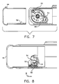
- Figure 3 is a partially cut-away bottom plan view of the camera of Figure 1. The door is in a closed position, the active light lock is in a open state.
- Figure 4 is the same view as Figure 3, but the door has been moved in the direction of arrow "A" from the closed position to a position between the closed position and a locking position. The active light lock and driver are likewise in intermediate positions.
- Figure 5 is the same view as Figure 4, but the door is has been moved further in the direction of arrow "A" into the a locking position. The active light lock is in a closed state.
- Figure 6 is the same view as Figure 5, but the door has been moved further in the direction of arrow "A" from the locking position into an intermediate position between the locking position and the open position. The active light lock is in the closed state. The pivot arm of the driver is flexed outward from the active light lock key by the engagement member of the door.
- Figure 7 is the same view as Figure 6, but the door has been moved into the open position.
- Figure 8 is the same view as Figure 7, but after the door has been reinserted and moved in the direction of arrow "B" from the open position and into the locking position.
- Figure 9 is the same view as Figure 8, with the door moved in the direction of arrow "B" from the locking position into an intermediate position between the locking position and closed position.
- Figure 10 is the same view as Figure 9, with the door in the closed position.
- Figure 11 is partially cut-away bottom plan view of another embodiment of the camera. The door is in the closed position.
- Figure 12 is a top perspective view of the camera of Figure 1.
-
- The
camera 10 of the invention has a body 12 that has afilm cartridge chamber 14.Other camera 10 features such as theexposure system 16,viewfinder 18, andflash unit 20 shown in Figure 1 are well known in the art and can be varied as desired. Thecamera 10 can be one-time use or reusable. One-time use is preferred, since thedriver 54, discussed in detail below, is most easily provided as a separate part, which would make user film loading cumbersome. As is the case with other one-time use cameras, it is preferred that the film be prewound from thecartridge 22 prior to use, to simplify film transport. - The
film cartridge 22 that thecamera 10 uses has anactive light lock 24. APS™ film is currently preferred. Theactive light lock 24 is movable from an open state to a closed state. In anAPS cartridge 22, thelight lock 24 is rotated for opening and closing. Other types of movement, for appropriate film cartridges, are within the scope of the invention. - The
camera 10 has aclosure 26 that includes aframe 28 that adjoins thefilm cartridge chamber 14. Theframe 28 can be a separate unit or can be continuous with the rest of the camera body 12. Theframe 28 defines a passage 30 for thecartridge 22 into thechamber 14 and defines rotational positions of theactive light lock 24 in the open and closed states. Theframe 28 has anouter rim 32 and aninner rim 34. Theinner rim 34 adjoins the passage 30. Theframe 28 is roughly rectangular and has a pair ofopposed tracks 36 on two of the sides of theframe 28. In the embodiment shown in the figures, the tworims outer rim 32 is recessed and acurb portion 38 of theinner rim 34 is shaped to provide a first portion 39 of an end light lock 40. On the fourth side, the tworims bulkhead 42. - The
closure 26 has adoor 44 that has about the same dimensions as theouter rim 32 of thetrack 36. Thedoor 44 has aflat panel 46 and a pair ofopposed margins 48 that are in slideable engagement with thetracks 36 when thedoor 44 is in theframe 28. Thedoor 44 has abrim 50, shown in Figure 12, on an end that extends between thetracks 36. On the bottom of thedoor 44, spaced apart from the edges of thedoor 44 is anengagement member 52. Thebrim 50 is shaped to fit against the third side of theframe 28 and provide the other portion 41 of the end light-lock 40. Thedoor 44 is slideable along thetracks 36 from a closed position, to an locking position, and then to an open position. In all of the positions, themargins 48 andtracks 36, where engaged, provide a light lock. When thedoor 44 is in the closed position, thecurb portion 38 andbrim 50 form a light lock on the third side and thedoor panel 46,outer rim 32, andbulkhead 42 form a light lock on the fourth side. In the locking position, thecurb portion 38 anddoor panel 46 form a light lock on the third side and thedoor panel 46 andbulkhead 42 provide a light lock on the fourth side. - The
closure 26 includes thedriver 54 that has an activelight lock key 56 that meshes with and is releaseably held by the activelight lock 24 of thecartridge 22. Thedriver 54 is shown in the figures as a loose part, but can be attached to thecamera 10 by a flexible stay (not shown) or the like. Thedriver 54 has apivot member 58 that extends outward from the key 56. In the embodiments shown in the figures, thepivot member 58 is recurvate and is roughly U-shaped with a first arm 60 that joins the key 56 and a second arm 61 that has acontact portion 64 that touches theengagement member 52. Thedriver 54 is movable relative to theframe 28 between a first position in which the activelight lock 24 and key 56 are in the open state and a second position in which the activelight lock 24 and key 56 are in the closed state. In the embodiment shown in the figures, the movement of thedriver 54 is a rotation about an axis of rotation of the activelight lock 24, but movement of thedriver 54 could be linear or some combination of movements depending upon the configuration of the activelight lock 24 of thefilm cartridge 22. - The
pivot member 58 andengagement member 52 mechanically engage thedoor 44 and thedriver 54 duringdoor 44 opening and closing. A variety of mechanism can be used for this purpose. The embodiments shown in the figures provide mechanical engagement by reciprocal teeth 66,67 on theengagement member 52 andpivot member 58, respectively. In the embodiment shown in Figures 1-10 and 12, theengagement member 52 andpivot member 58 each have a single toot 66,67. In the embodiment shown in Figure 11, theengagement member 52 is atoothed rack 68 and thepivot member 58 is a reciprocallytoothed sector 70. Referring to Figures 3-7, theengagement member 52 anddriver 54 coact to move thedriver 54, in the direction of arrow "A", from a first position, shown in Figure 3, to a second position, shown in Figure 5, when thedoor 44 is slid from the closed position to the locking position. The activelight lock 24 is in the open state when thedriver 54 is in the first position. The activelight lock 24 is in the closed state when thedriver 54 is in the second position. Referring to Figures 5-6, thedriver 54 remains in the second position when thedoor 44 is moved, in the direction of arrow "A", from the locking position to the open position. Thedriver 54 also disengages from theengagement member 52 when thedoor 44 is moved from the locking position to the open position. Free play is provided to allow theengagement member 52 to move past thedriver 54. In the embodiments shown in the figures, the free play results from resilience of thedriver 54, which allows thecontact portion 64 to be bent aside to release thedoor 44, as shown in Figure 6. Referring to Figures 8-10, thedoor 44 is reinserted and moved in the direction of arrow "B". Theengagement member 52 moves thedriver 54 into the first position, if necessary, and then retains thedriver 54 in the first position until thedoor 44 reaches the closed position, as shown in Figure 10. Thecontact portion 64 is resiliently bent toward the key 56 during this process, to allow theengagement member 52 to clear.
Claims (8)
- A closure for use with a film cartridge having an active light lock movable from an open state to a closed state, said closure comprising:a frame having a pair of opposed tracks, said frame defining a passage for said cartridge;a door having a pair of opposed margins in slideable engagement with said tacks, said door sliding along said tracks from a closed position, to an locking position, and from said locking position to an open position;a driver having an active light lock key, said driver being movable relative to said frame from a first position wherein said key is disposed to hold the active light lock in the open state and a second position wherein said key is disposed to hold the active light lock in the closed state, wherein said sliding of said door from said closed position to said locking position moves said driver from said first position to said second position, and said sliding of said door from said locking position to said open position retains said driver in said second position.
- A camera comprising:a film cartridge having an active light lock movable from an open state to a closed state;a body having a film cartridge chamber holding said film cartridge and a frame adjoining said film cartridge chamber, said frame having a pair of opposed tracks, said frame defining a passage for said cartridge;a door having a pair of opposed margins in slideable engagement with said tacks, said door sliding along said tracks from a closed position, to an locking position, and from said locking position to an open position;a driver having an active light lock key releaseably held by said active light lock, said driver being movable relative to said frame from a first position wherein said key holds said active light lock in said open state and a second position wherein said key holds said active light lock in said closed state,
wherein said sliding of said door from said closed position to said locking position moves said driver from said first position to said second position, and said sliding of said door from said locking position to said open position retains said driver in said second position. - The apparatus of claim 1 or 2 wherein said door and said frame are disposed in light-locking relation when said door is disposed in said closed and locking positions.
- The apparatus of claim 1, 2, or 3 further comprising a pivot arm extending outward from said key and an engagement member joined to said door, said pivot arm and said engagement member mechanically engaging said door to said driver when said door is in said locking position.
- The apparatus of claim 4 wherein said pivot arm is resiliently biased against disengagement from said engagement member.
- The apparatus of claim 4 or 5 wherein said pivot arm is recurvate.
- The apparatus of claim 4, 5, or 6 wherein said engagement member is a single tooth and said pivot arm is a single tooth.
- The apparatus of claim 4,5, or 6 wherein said engagement member is a rack and said pivot arm is a reciprocally toothed sector.
Applications Claiming Priority (2)
| Application Number | Priority Date | Filing Date | Title |
|---|---|---|---|
| US218504 | 1994-03-25 | ||
| US09/218,504 US6049679A (en) | 1998-12-22 | 1998-12-22 | Active light locking camera closure and camera |
Publications (2)
| Publication Number | Publication Date |
|---|---|
| EP1014166A2 true EP1014166A2 (en) | 2000-06-28 |
| EP1014166A3 EP1014166A3 (en) | 2003-04-02 |
Family
ID=22815393
Family Applications (1)
| Application Number | Title | Priority Date | Filing Date |
|---|---|---|---|
| EP99204102A Withdrawn EP1014166A3 (en) | 1998-12-22 | 1999-12-02 | Camera with means for opening and closing the light shielding door of a cartgridge |
Country Status (3)
| Country | Link |
|---|---|
| US (1) | US6049679A (en) |
| EP (1) | EP1014166A3 (en) |
| JP (1) | JP2000187267A (en) |
Families Citing this family (1)
| Publication number | Priority date | Publication date | Assignee | Title |
|---|---|---|---|---|
| US6529690B1 (en) * | 1998-09-08 | 2003-03-04 | Olympus Optical Co., Ltd. | Camera for preventing plastic deformation of locking member of light-shielding door or film cartridge |
Citations (5)
| Publication number | Priority date | Publication date | Assignee | Title |
|---|---|---|---|---|
| EP0661587A1 (en) * | 1993-12-28 | 1995-07-05 | Canon Kabushiki Kaisha | Camera or apparatus adapted to use film cartridge or device applicable to such camera or apparatus |
| JPH08262639A (en) * | 1995-03-22 | 1996-10-11 | Konica Corp | Film unit with lens |
| US5638152A (en) * | 1996-02-16 | 1997-06-10 | Eastman Kodak Company | Bi-directional spring device for opening and closing light shield of film cassette |
| JPH09230470A (en) * | 1996-02-28 | 1997-09-05 | Fuji Photo Film Co Ltd | Camera using film cartridge provided with light shielding door capable of opening/closing |
| EP0743550B1 (en) * | 1995-05-15 | 2002-09-11 | Fuji Photo Film Co., Ltd. | Lens-fitted photo film unit and method of producing the same |
Family Cites Families (2)
| Publication number | Priority date | Publication date | Assignee | Title |
|---|---|---|---|---|
| US5305039A (en) * | 1993-04-12 | 1994-04-19 | Eastman Kodak Company | Photographic camera with light seal/latch device for loading door |
| US5828921A (en) * | 1993-12-28 | 1998-10-27 | Canon Kabushiki Kaisha | Camera or apparatus adapted to use film cartridge or device applicable to such camera or apparatus |
-
1998
- 1998-12-22 US US09/218,504 patent/US6049679A/en not_active Expired - Fee Related
-
1999
- 1999-12-02 EP EP99204102A patent/EP1014166A3/en not_active Withdrawn
- 1999-12-13 JP JP11352593A patent/JP2000187267A/en active Pending
Patent Citations (5)
| Publication number | Priority date | Publication date | Assignee | Title |
|---|---|---|---|---|
| EP0661587A1 (en) * | 1993-12-28 | 1995-07-05 | Canon Kabushiki Kaisha | Camera or apparatus adapted to use film cartridge or device applicable to such camera or apparatus |
| JPH08262639A (en) * | 1995-03-22 | 1996-10-11 | Konica Corp | Film unit with lens |
| EP0743550B1 (en) * | 1995-05-15 | 2002-09-11 | Fuji Photo Film Co., Ltd. | Lens-fitted photo film unit and method of producing the same |
| US5638152A (en) * | 1996-02-16 | 1997-06-10 | Eastman Kodak Company | Bi-directional spring device for opening and closing light shield of film cassette |
| JPH09230470A (en) * | 1996-02-28 | 1997-09-05 | Fuji Photo Film Co Ltd | Camera using film cartridge provided with light shielding door capable of opening/closing |
Non-Patent Citations (2)
| Title |
|---|
| PATENT ABSTRACTS OF JAPAN vol. 1997, no. 02, 28 February 1997 (1997-02-28) -& JP 08 262639 A (KONICA CORP), 11 October 1996 (1996-10-11) * |
| PATENT ABSTRACTS OF JAPAN vol. 1998, no. 01, 30 January 1998 (1998-01-30) -& JP 09 230470 A (FUJI PHOTO FILM CO LTD), 5 September 1997 (1997-09-05) * |
Also Published As
| Publication number | Publication date |
|---|---|
| JP2000187267A (en) | 2000-07-04 |
| EP1014166A3 (en) | 2003-04-02 |
| US6049679A (en) | 2000-04-11 |
Similar Documents
| Publication | Publication Date | Title |
|---|---|---|
| US4469423A (en) | Film light shield | |
| US20030128397A1 (en) | Camera and underwater housing having two-shot molded knob seat | |
| US4240735A (en) | Protective cover for taking lens of camera | |
| EP1024396B1 (en) | Lens-carrying film unit having protective cover | |
| JP4357766B2 (en) | Camera lens barrier device | |
| US6049679A (en) | Active light locking camera closure and camera | |
| JPH059710Y2 (en) | ||
| US20030118333A1 (en) | Underwater camera having viewports bearing on viewfinder tunnel of frame | |
| JPH10206954A (en) | Camera | |
| US5796464A (en) | Camera with slide-open closure flexed to release for opening | |
| US4527873A (en) | Camera loading door interlock | |
| JPS5973730U (en) | Cartridge storage chamber lid lock opening/closing device for cameras with disc-shaped film cartridges | |
| JP3870239B2 (en) | camera | |
| JPH059711Y2 (en) | ||
| JP3832800B2 (en) | camera | |
| JPS59121031A (en) | Camera | |
| JP2000111989A (en) | Camera with barrier | |
| JPH059712Y2 (en) | ||
| JPH028267Y2 (en) | ||
| JPH08278548A (en) | Rear cover opening/closing mechanism provided with film confirming window | |
| JPS6215798Y2 (en) | ||
| JP3963335B2 (en) | camera | |
| JPH028269Y2 (en) | ||
| JP2004037742A (en) | Film bag | |
| JP3064495B2 (en) | camera |
Legal Events
| Date | Code | Title | Description |
|---|---|---|---|
| PUAI | Public reference made under article 153(3) epc to a published international application that has entered the european phase |
Free format text: ORIGINAL CODE: 0009012 |
|
| AK | Designated contracting states |
Kind code of ref document: A2 Designated state(s): AT BE CH CY DE DK ES FI FR GB GR IE IT LI LU MC NL PT SE |
|
| AX | Request for extension of the european patent |
Free format text: AL;LT;LV;MK;RO;SI |
|
| PUAL | Search report despatched |
Free format text: ORIGINAL CODE: 0009013 |
|
| AK | Designated contracting states |
Kind code of ref document: A3 Designated state(s): AT BE CH CY DE DK ES FI FR GB GR IE IT LI LU MC NL PT SE Designated state(s): AT BE CH CY DE DK ES FI FR GB GR IE IT LI LU MC NL PT SE |
|
| AX | Request for extension of the european patent |
Extension state: AL LT LV MK RO SI |
|
| RIC1 | Information provided on ipc code assigned before grant |
Ipc: 7G 03B 17/30 A |
|
| 17P | Request for examination filed |
Effective date: 20030915 |
|
| 17Q | First examination report despatched |
Effective date: 20031017 |
|
| AKX | Designation fees paid |
Designated state(s): DE FR GB |
|
| STAA | Information on the status of an ep patent application or granted ep patent |
Free format text: STATUS: THE APPLICATION IS DEEMED TO BE WITHDRAWN |
|
| 18D | Application deemed to be withdrawn |
Effective date: 20040228 |