EP1013846A1 - Articulated arm for the support and stretching out of awnings - Google Patents
Articulated arm for the support and stretching out of awnings Download PDFInfo
- Publication number
- EP1013846A1 EP1013846A1 EP98830784A EP98830784A EP1013846A1 EP 1013846 A1 EP1013846 A1 EP 1013846A1 EP 98830784 A EP98830784 A EP 98830784A EP 98830784 A EP98830784 A EP 98830784A EP 1013846 A1 EP1013846 A1 EP 1013846A1
- Authority
- EP
- European Patent Office
- Prior art keywords
- arm
- articulated arm
- articulated
- elastic member
- bent position
- Prior art date
- Legal status (The legal status is an assumption and is not a legal conclusion. Google has not performed a legal analysis and makes no representation as to the accuracy of the status listed.)
- Granted
Links
Images


Classifications
-
- E—FIXED CONSTRUCTIONS
- E04—BUILDING
- E04F—FINISHING WORK ON BUILDINGS, e.g. STAIRS, FLOORS
- E04F10/00—Sunshades, e.g. Florentine blinds or jalousies; Outside screens; Awnings or baldachins
- E04F10/02—Sunshades, e.g. Florentine blinds or jalousies; Outside screens; Awnings or baldachins of flexible canopy materials, e.g. canvas ; Baldachins
- E04F10/06—Sunshades, e.g. Florentine blinds or jalousies; Outside screens; Awnings or baldachins of flexible canopy materials, e.g. canvas ; Baldachins comprising a roller-blind with means for holding the end away from a building
- E04F10/0644—Sunshades, e.g. Florentine blinds or jalousies; Outside screens; Awnings or baldachins of flexible canopy materials, e.g. canvas ; Baldachins comprising a roller-blind with means for holding the end away from a building with mechanisms for unrolling or balancing the blind
- E04F10/0651—Sunshades, e.g. Florentine blinds or jalousies; Outside screens; Awnings or baldachins of flexible canopy materials, e.g. canvas ; Baldachins comprising a roller-blind with means for holding the end away from a building with mechanisms for unrolling or balancing the blind acting on the arms
-
- E—FIXED CONSTRUCTIONS
- E04—BUILDING
- E04F—FINISHING WORK ON BUILDINGS, e.g. STAIRS, FLOORS
- E04F10/00—Sunshades, e.g. Florentine blinds or jalousies; Outside screens; Awnings or baldachins
- E04F10/02—Sunshades, e.g. Florentine blinds or jalousies; Outside screens; Awnings or baldachins of flexible canopy materials, e.g. canvas ; Baldachins
- E04F10/06—Sunshades, e.g. Florentine blinds or jalousies; Outside screens; Awnings or baldachins of flexible canopy materials, e.g. canvas ; Baldachins comprising a roller-blind with means for holding the end away from a building
- E04F10/0611—Sunshades, e.g. Florentine blinds or jalousies; Outside screens; Awnings or baldachins of flexible canopy materials, e.g. canvas ; Baldachins comprising a roller-blind with means for holding the end away from a building with articulated arms supporting the movable end of the blind for deployment of the blind
- E04F10/0618—Sunshades, e.g. Florentine blinds or jalousies; Outside screens; Awnings or baldachins of flexible canopy materials, e.g. canvas ; Baldachins comprising a roller-blind with means for holding the end away from a building with articulated arms supporting the movable end of the blind for deployment of the blind whereby the pivot axis of the articulation is perpendicular to the roller
Definitions
- the present invention relates to an articulated arm of the type used to support and extend tents, in particular awnings for protecting terraces, balconies and the like from sunlight.
- the articulated arm of the present invention is of the type comprising a pair of articulated half-arms movable from a non-operative bent position and an extended position, and provided with an elastic member, fastened to each of said half-arms, which opposes to the bending of the arm.
- Articulated arms as set forth above are used to keep the awnings' cloth extended, as well as to take part in unwinding said awnings.
- the elastic member is located so as to keep the arm extended, i.e. to keep it in its normal operative position, when the load to which the elastic member is subjected is not so heavy as to damage with time said elastic member.
- the elastic member remains undamaged.
- Said dangerous standstills are, for example, winter, when extremely cold temperatures facilitate the yielding of metal springs of elastic members, or storage periods before sale.
- awnings are sold in specific time of the year, which takes place during the pre-summer season. If awnings are not sold during the same season of their manufacture, they will most probably not be sold until the following season, when the articulated arms may have suffered severe functionality loss.
- the technical problem which underlies the present invention is to provide an articulated arm as to overcome the drawbacks mentioned with reference to the prior art.
- an articulated arm for the support and the extension of awnings comprising:
- the main advantage of the articulated arm according to the present invention lies in the possibility of releasing said elastic member, thus preventing it from yielding during standstills.
- the outdoor awning of the type which is mounted on a vertical wall and is apt to extend in order to create a shady area is indicated 1 as a whole.
- winding roller 2 rotatably connected to the vertical wall at its ends, which is provided with rotating means 3 of the passive kind, i.e. that can to rotate the roller in each of the two rotation directions only when it is outerly operated by means of a hook 4 and a rod, not shown.
- a horizontal bar 5 Opposed to the roller 2, which is horizontally mounted, is a horizontal bar 5 which can be operated, as it will be made clear herebelow, so as to be approached or moved away from said roller 2.
- the awning 1 comprises elastic return means which, as it will be made clear herebelow, operate independently from said rotating means 3 of the winding roller 2.
- the awning 1 comprises a pair of supporting arms 7, symmetrically placed at the sides of the cloth 6, which can extend and be bent in order to wind and unwind the awning 1.
- every supporting arm 7 that, in this preferred embodiment are identical, have a first and a second half-arm, respectively indicated 8 and 9.
- the half-arms 8, 9 consist of an elongated box-like member 10 which is hollow. They are connected therebetween along respective first and second close ends 11 and 12 by an intermediate joint 13 comprising a first vertical-axis rotating pin 14.
- the intermediate joint 13 defines a bending whose inner side is oriented toward the outside of the awning 1.
- Both close ends 11,12 are open at their respective hollow sections defined by the box-like member 10.
- the arm 7 comprises a first articulated end 15, opposed to the first close end 11 of the first half-arm 8, and a second articulated end 16, opposed to the second close end 12 of the second half-arm 9.
- the second articulated end 16 is rotatably connected to the horizontal bar, while the first articulated end, is rotatably connected to a supporting member 17 apt to be fastened to the wall in a suitable position.
- the first articulated end 15 comprises an articulation member 18 which has a bushing 19 having a vertical axis.
- the articulation member 18, made of metal, is simply forced inside the box-like member 10, which is also metallic, closing the corresponding opening.
- the bushing 19 houses a second rotating pin 20, connected to the supporting member 17.
- the elastic return means of arms 7 formed by an elastic member, indicated 21 as a whole, which is joined to said first and second half-arm 8,9.
- the elastic member 21 is of the elongated type and comprises a first end 22 which is connected to the first half-arm 8 at the articulation member 18, and a second end 23 which is connected to the second half-arm 9 at a point thereof, for example the second articulated end 16.
- the elastic member 21 comprises an helical spring 24 connected to a flexible member 25, in particular a roller chain.
- the helical spring 24 is entirely housed inside the first half-arm 8 in the respective box-like member 10. It ends with a hook 26 connected to the first link of the roller chain 25 which is housed inside said first and second half-arms 8,9 in their respective box-like members 10.
- the chain 25 runs through the opened close ends 11,12 and it is in contact with the first rotating pin 14 on the outer side of the bending between the first and the second half-arm.
- the elastic member 21 is stretched between its ends 22, 23. Therefore, it tends to assume the configuration of lesser length, or extension, pressing the first rotating means 14 to a direction which proceeds from the outer to the inner side of the bending. In other words, the elastic member 21 opposes to the bending of the arm 7 and tends to keep the half-arms 8,9 in the position which is closer to their reciprocal alignment, i.e. in the extended position supporting the bar 5 and the cloth 6.
- the arm 7 according to the invention comprises, as it will be made clearer herebelow, loosening means 27 of said elastic member 21 which in the present embodiment are joined to the first half-arm 8.
- said loosening means are provided with a screw coupling indicated 27 as a whole, of, for example, the open-sleeve type. The latter is located next to the first articulated end 15.
- the screw coupling 27 comprises a first screw 28, engaged to a first end 29 of the sleeve which is indicated 30.
- the first screw 28 is provided with a circular eye 31 which is hooked to the helical spring 24 by a second hook 32.
- the first screw 28 is actually secured or fastened to the respective first end 29 of the sleeve 30.
- the screw coupling can comprise a connecting member integrally built with the sleeve 30 however, in order to use the standard screw couplings which are easily available on sale, it is sufficient to skillfully break the thread of the first screw 28 in order to prevent it from turning, acting so that its transmission efficiency is lower than the transmission efficiency of the second screw coupling screw indicated 33.
- the second screw 33 is engaged to the second end 34 of the sleeve 30. It is provided with an Allen head 35 which is secured into a first flared hole 36; drilled through the articulation member 18 and the bushing 19. The Allen head 35 is free to rotate in the first hole 36 which is opened into the opening of the bushing 19.
- the bushing 19 is provided with a second hole 37 opposed to the first hole 36. Obviously, the holes 36, 37 are continuously aligned with the axis of the screw coupling 27, with the first half-arm 8 and with the portion of the elastic member 21 which is housed inside the first half-arm 8.
- the pin 20 is also provided with a third hole 38 corresponding to said first and second holes 36, 37. Said holes 36, 37, 38 make up, when they are aligned, an access opening to the Allen head 35; an Allen wrench B can be inserted through this opening in order to reach the screw coupling 27, i.e. the loosening means of the arm 7.
- the loosening means can be operated when the arm 7 is in its non-operative bent position, i.e. it is possible to go through said access opening 36,37,38 when the first half-arm 8 and the second half-arm 9 closely bent and parallel therebetween (figures 2, 3) and to the horizontal bar 5, to the winding roller 2 and to the wall, not shown.
- the third hole 38 of the cylindrical type, has a fixed axis which is parallel to the first half-arm 8 when the arm 7 is in the bent position, allowing the alignment of the holes 36,37,38 only in this particular position.
- the elastic return means consisting of the elastic members 21 of each arm 7, cooperate in unwinding the same awning 1 and to keep the cloth 6 extended.
- the awning is kept constantly unwound or it is subjected to an unwinding-winding cycle corresponding, for example, to the day-night cycle.
- the elastic member 21 is seldom subjected to the maximum load and anyway for limited periods of time.
- the standstill period of the awning 1 is for example winter, or the period before sale or also, and this is the longest period of all, if the awning is not sold during the top selling season, i.e. before summer, and remains unsold until the following top selling season.
- the awning 1 is usually stored with the arms 7 in a completely bent position: in this case, in order to prevent the damaging of the elastic member 21, it is sufficient to operate the loosening means 27 and move the elastic member 21 to the unloaded position.
- This loosening operation can be carried out directly at the factory, while the elastic member 21 will be placed in its operative position after sale. Furthermore, the elastic member 21 will have to be loosened during maintenance operations, scheduled during the season which immediately follows summer.
- the articulated arm can be of the type comprising a plurality of articulated half-arms, provided with one or more elastic members to be loosened.
- the elastic member can be modified in its shape and position in order to meet different requirements of structural setting.
- the loosening means can form a part of the elastic member which can be placed in different positions, not only in proximity of the winding roller but also, for example, in proximity of the horizontal bar or the intermediate joint.
- the screw coupling can be replaced by similar loosening systems, such as a releasing and hooking system provided with hollows or other limit stops.
- the articulated arm can be made with simple modifications of extremely low design impact and low costs.
Landscapes
- Engineering & Computer Science (AREA)
- Architecture (AREA)
- Civil Engineering (AREA)
- Structural Engineering (AREA)
- Building Awnings And Sunshades (AREA)
- Manipulator (AREA)
- Tents Or Canopies (AREA)
Abstract
Description
- The present invention relates to an articulated arm of the type used to support and extend tents, in particular awnings for protecting terraces, balconies and the like from sunlight.
- The articulated arm of the present invention is of the type comprising a pair of articulated half-arms movable from a non-operative bent position and an extended position, and provided with an elastic member, fastened to each of said half-arms, which opposes to the bending of the arm.
- Articulated arms as set forth above are used to keep the awnings' cloth extended, as well as to take part in unwinding said awnings.
- The elastic member is located so as to keep the arm extended, i.e. to keep it in its normal operative position, when the load to which the elastic member is subjected is not so heavy as to damage with time said elastic member.
- In fact, whichever elastic member, if subjected to a heavy stretching load, suffers damage with time with a reduction of the elastic constant.
- If the standstill during which the arm is stored in the bent position and the elastic member is subject to the maximum load is limited in time, for example one night or a few days, the elastic member remains undamaged.
- If, on the contrary, standstills are longer, the arm may lose part of its functionality and should be replaced, as articulated arms are built using box-like members and parts which are irreversibly fixed and cannot be disassembled to replace the elastic member.
- Said dangerous standstills are, for example, winter, when extremely cold temperatures facilitate the yielding of metal springs of elastic members, or storage periods before sale.
- As it is known, awnings are sold in specific time of the year, which takes place during the pre-summer season. If awnings are not sold during the same season of their manufacture, they will most probably not be sold until the following season, when the articulated arms may have suffered severe functionality loss.
- The technical problem which underlies the present invention is to provide an articulated arm as to overcome the drawbacks mentioned with reference to the prior art.
- Said problem is solved by an articulated arm for the support and the extension of awnings, comprising:
- a first and a second half-arms, connected at their respective close ends thereof by means of an intermediate joint, and each provided with a respective articulated end opposed to said close end, said first and second half-arm being movable between a non-operative bent position and an extended supporting position of the articulated arm; and
- an elastic member, fastened to said first and second half-arms, which opposes to the bending of said articulated arm;
- The main advantage of the articulated arm according to the present invention lies in the possibility of releasing said elastic member, thus preventing it from yielding during standstills.
- The present invention will be hereinafter disclosed according to a preferred embodiment thereof, shown as a non-limiting example. Reference will be made to the figures of the annexed drawings wherein:
- figure 1 shows a partly sectioned perspective view of an awning in its extended position, incorporating an articulated arm according to the present invention;
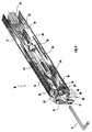
- figure 2 shows a partly sectioned perspective view of the articulated arm of figure 1 in an operative mode;
- figure 3 shows a partly sectioned perspective view of the articulated arm of figure 1 in a non-operative mode; and
- figure 4 shows a partly sectioned perspective view from a different angle of a detail of the articulated arm of figure 1.
-
- With reference in particular to figure 1, the outdoor awning of the type which is mounted on a vertical wall and is apt to extend in order to create a shady area, is indicated 1 as a whole.
- It comprises a winding roller 2, rotatably connected to the vertical wall at its ends, which is provided with rotating means 3 of the passive kind, i.e. that can to rotate the roller in each of the two rotation directions only when it is outerly operated by means of a
hook 4 and a rod, not shown. - Opposed to the roller 2, which is horizontally mounted, is a horizontal bar 5 which can be operated, as it will be made clear herebelow, so as to be approached or moved away from said roller 2.
- A cloth 6, which is wound around the roller 2 and is fastened as usual to the bar 5, extends between the roller 2 and the bar 5. In order to keep the cloth 6 always extended, the awning 1 comprises elastic return means which, as it will be made clear herebelow, operate independently from said rotating means 3 of the winding roller 2.
- Moreover, the awning 1 comprises a pair of supporting arms 7, symmetrically placed at the sides of the cloth 6, which can extend and be bent in order to wind and unwind the awning 1.
- According to the present invention every supporting arm 7 that, in this preferred embodiment are identical, have a first and a second half-arm, respectively indicated 8 and 9.
- The half-
arms 8, 9 consist of an elongated box-like member 10 which is hollow. They are connected therebetween along respective first and secondclose ends 11 and 12 by anintermediate joint 13 comprising a first vertical-axis rotating pin 14. Theintermediate joint 13 defines a bending whose inner side is oriented toward the outside of the awning 1. - Both
close ends 11,12 are open at their respective hollow sections defined by the box-like member 10. - The arm 7 comprises a first articulated
end 15, opposed to the first close end 11 of the first half-arm 8, and a second articulatedend 16, opposed to the secondclose end 12 of the second half-arm 9. - The second articulated
end 16 is rotatably connected to the horizontal bar, while the first articulated end, is rotatably connected to a supportingmember 17 apt to be fastened to the wall in a suitable position. - The first articulated
end 15 comprises anarticulation member 18 which has a bushing 19 having a vertical axis. Thearticulation member 18, made of metal, is simply forced inside the box-like member 10, which is also metallic, closing the corresponding opening. - The bushing 19 houses a second rotating
pin 20, connected to the supportingmember 17. - According to the present invention the elastic return means of arms 7 formed by an elastic member, indicated 21 as a whole, which is joined to said first and second half-
arm 8,9. - The
elastic member 21 is of the elongated type and comprises afirst end 22 which is connected to the first half-arm 8 at thearticulation member 18, and asecond end 23 which is connected to the second half-arm 9 at a point thereof, for example the second articulatedend 16. - The
elastic member 21 comprises anhelical spring 24 connected to aflexible member 25, in particular a roller chain. - The
helical spring 24 is entirely housed inside the first half-arm 8 in the respective box-like member 10. It ends with ahook 26 connected to the first link of theroller chain 25 which is housed inside said first and second half-arms 8,9 in their respective box-like members 10. Thechain 25 runs through the openedclose ends 11,12 and it is in contact with the first rotating pin 14 on the outer side of the bending between the first and the second half-arm. - The
elastic member 21 is stretched between itsends elastic member 21 opposes to the bending of the arm 7 and tends to keep the half-arms 8,9 in the position which is closer to their reciprocal alignment, i.e. in the extended position supporting the bar 5 and the cloth 6. - The arm 7 according to the invention comprises, as it will be made clearer herebelow, loosening
means 27 of saidelastic member 21 which in the present embodiment are joined to the first half-arm 8. - In the present embodiment, said loosening means are provided with a screw coupling indicated 27 as a whole, of, for example, the open-sleeve type. The latter is located next to the first articulated
end 15. - The
screw coupling 27 comprises afirst screw 28, engaged to afirst end 29 of the sleeve which is indicated 30. Thefirst screw 28 is provided with acircular eye 31 which is hooked to thehelical spring 24 by asecond hook 32. - The
first screw 28 is actually secured or fastened to the respectivefirst end 29 of thesleeve 30. Instead of said screw, the screw coupling can comprise a connecting member integrally built with thesleeve 30 however, in order to use the standard screw couplings which are easily available on sale, it is sufficient to skillfully break the thread of thefirst screw 28 in order to prevent it from turning, acting so that its transmission efficiency is lower than the transmission efficiency of the second screw coupling screw indicated 33. - The
second screw 33 is engaged to the second end 34 of thesleeve 30. It is provided with an Allenhead 35 which is secured into a first flaredhole 36; drilled through thearticulation member 18 and the bushing 19. The Allenhead 35 is free to rotate in thefirst hole 36 which is opened into the opening of the bushing 19. - The
bushing 19 is provided with asecond hole 37 opposed to thefirst hole 36. Obviously, theholes screw coupling 27, with the first half-arm 8 and with the portion of theelastic member 21 which is housed inside the first half-arm 8. - The
pin 20 is also provided with athird hole 38 corresponding to said first andsecond holes holes head 35; an Allen wrench B can be inserted through this opening in order to reach thescrew coupling 27, i.e. the loosening means of the arm 7. - The loosening means can be operated when the arm 7 is in its non-operative bent position, i.e. it is possible to go through said access opening 36,37,38 when the first half-arm 8 and the second half-
arm 9 closely bent and parallel therebetween (figures 2, 3) and to the horizontal bar 5, to the winding roller 2 and to the wall, not shown. - To this purpose, the
third hole 38, of the cylindrical type, has a fixed axis which is parallel to the first half-arm 8 when the arm 7 is in the bent position, allowing the alignment of theholes - In said position it is possible, by operating on the Allen
head 35 by means of the wrench B or by a similar tool, to loosen theelastic member 21 from an operative position, which in the bent positions corresponds to the maximum load applied to saidelastic member 21, to an unloaded position of partial loosening wherein the elastic features of theelastic member 21, and in particular thehelical spring 24, are not deteriorated. - When the
member 21 is in its operative position, it is possible to maneuver the awning 1 by acting on the rotating means 3 in the usual way. The elastic return means, consisting of theelastic members 21 of each arm 7, cooperate in unwinding the same awning 1 and to keep the cloth 6 extended. - During the operative period of the awning 1, for example in summer, the awning is kept constantly unwound or it is subjected to an unwinding-winding cycle corresponding, for example, to the day-night cycle.
- Therefore, during the operative period, the
elastic member 21 is seldom subjected to the maximum load and anyway for limited periods of time. - The standstill period of the awning 1 is for example winter, or the period before sale or also, and this is the longest period of all, if the awning is not sold during the top selling season, i.e. before summer, and remains unsold until the following top selling season.
- During such standstill periods the awning 1 is usually stored with the arms 7 in a completely bent position: in this case, in order to prevent the damaging of the
elastic member 21, it is sufficient to operate the loosening means 27 and move theelastic member 21 to the unloaded position. - This loosening operation can be carried out directly at the factory, while the
elastic member 21 will be placed in its operative position after sale. Furthermore, theelastic member 21 will have to be loosened during maintenance operations, scheduled during the season which immediately follows summer. - The articulated arm described above can rely to different embodiments which would anyway fall within the scope of the present invention.
- In particular, the articulated arm can be of the type comprising a plurality of articulated half-arms, provided with one or more elastic members to be loosened.
- Furthermore, the elastic member can be modified in its shape and position in order to meet different requirements of structural setting. In a similar way the loosening means can form a part of the elastic member which can be placed in different positions, not only in proximity of the winding roller but also, for example, in proximity of the horizontal bar or the intermediate joint.
- The screw coupling can be replaced by similar loosening systems, such as a releasing and hooking system provided with hollows or other limit stops.
- Besides the above-mentioned advantage, the articulated arm can be made with simple modifications of extremely low design impact and low costs.
- Moreover, it can also be used to adjust the load to which the elastic member is subjected. Such adjustment can be carried out at the factory, and allows the use of standard helical springs suiting different articulated arms instead of calibrated springs.
- In order to meet further contingencies, a man skilled in the art will be able to provide the above-described articulated arm with further different variations and all of them, however, falling within the protective scope of the present invention, as defined by claims annexed hereinafter.
Claims (15)
- . An articulated arm (7) for the support and extension of awnings (1) comprising:a first and a second half-arm (8, 9), connected at respective close ends (11, 12) by means of an intermediate joint (13) and each provided with a respective articulated end (15, 16) opposed to said close end (11, 12) said first and second half-arm (8, 9) being movable between a non-operative bent position and an extended, supporting position of the articulated arm (7); andan elastic member (21) connected to said first and second half-arm (8, 9) which opposes to the bending of said articulated arm (7); characterized in that it comprises:loosening means (27) of said elastic member (21) which are joined with said first or second half-arm (8,9), which are operable in the bent position of said articulated arm (7).
- The articulated arm (7) according to claim 1, wherein the elastic member (21) is of the elongated type.
- The articulated arm (7) according to claim 2, wherein said first and second half-arm (8, 9) are formed by an elongated box-like member, said elastic member (21) being housed inside said first and second half-arms (8, 9).
- The articulated arm (7) according to claim 3, wherein said elastic member (21) comprises an helical spring (24) housed inside said first half-arm.
- The articulated arm (7) according to claims 3 or 4, wherein said intermediate joint (13) defines a bending and comprises a pin (14), said elastic member (21) having a first end (22) connected to the first half-arm (8), and a second end (23) connected to the second half-arm (9), and being in contact with said pin (14) at the inner side of the bending.
- The articulated arm (7) according to claim 5, wherein said elastic member (21) comprises a flexible member (25) which is in contact with said pin (14).
- The articulated arm (7) according to claim 6, wherein said flexible member comprises a roller chain (25).
- The articulated arm (7) according to one of preceding claims, wherein said loosening means comprise a screw coupling (27).
- The articulated arm (7) according to claim 8, comprising a first and a second articulated end (15, 16) of said first and second half-arm (8,9) respectively, said screw coupling (27) being placed next to one of said articulated ends (15, 16) which comprises an articulation member (18) presenting an opening (36, 37, 38) which can be accessed in order to operate said screw coupling (27) when the articulated arm (7) is in the bent position.
- The articulated arm (7) according to claim 9, wherein said articulation member (18) comprises a bushing (19) which houses a rotating pin (20), said bushing having a first and a second hole (36, 37) aligned with the turnbuckle's (27) axis and said rotating pin (20) having, at said first and second hole (36, 37) a third cylindrical hole (38) whose axis is parallel to one of said first and second half-arms (8, 9), which corresponds to said articulation member (18) when the articulated arm (7) is in its bent position, said first, second and third hole being in alignment therebetween when the arm (7) is in its bent position so to realize said opening.
- The articulated arm (7) according to claim 10, wherein said articulation member is located at said first articulated end (15).
- The articulated arm (7) according to one of claims 8 to 11, wherein said screw coupling comprises a sleeve (30) and a screw (28) having a secured head which is free to rotate inside said first hole (36) of the bushing (19).
- The articulated arm (7) according to claim 12, wherein the sleeve (30) is an open sleeve.
- The articulated arm (7) according to claim 12, wherein the head (35) is an Allen head.
- An awning (1) comprising at least one articulated arm (7) according to any of preceding claims.
Priority Applications (3)
| Application Number | Priority Date | Filing Date | Title |
|---|---|---|---|
| EP98830784A EP1013846B1 (en) | 1998-12-24 | 1998-12-24 | Articulated arm for the support and stretching out of awnings |
| DE69833744T DE69833744T2 (en) | 1998-12-24 | 1998-12-24 | Articulated arm for carrying and stretching awnings |
| AT98830784T ATE319893T1 (en) | 1998-12-24 | 1998-12-24 | ARTICLED ARM FOR CARRYING AND STRETCHING AWNINGS |
Applications Claiming Priority (1)
| Application Number | Priority Date | Filing Date | Title |
|---|---|---|---|
| EP98830784A EP1013846B1 (en) | 1998-12-24 | 1998-12-24 | Articulated arm for the support and stretching out of awnings |
Publications (2)
| Publication Number | Publication Date |
|---|---|
| EP1013846A1 true EP1013846A1 (en) | 2000-06-28 |
| EP1013846B1 EP1013846B1 (en) | 2006-03-08 |
Family
ID=8236932
Family Applications (1)
| Application Number | Title | Priority Date | Filing Date |
|---|---|---|---|
| EP98830784A Expired - Lifetime EP1013846B1 (en) | 1998-12-24 | 1998-12-24 | Articulated arm for the support and stretching out of awnings |
Country Status (3)
| Country | Link |
|---|---|
| EP (1) | EP1013846B1 (en) |
| AT (1) | ATE319893T1 (en) |
| DE (1) | DE69833744T2 (en) |
Cited By (4)
| Publication number | Priority date | Publication date | Assignee | Title |
|---|---|---|---|---|
| ES2235554A1 (en) * | 2001-03-23 | 2005-07-01 | Gaviota Simbac, S.L. | Axial spring tensioner for tensioning arms of awning, has piece whose axial unit is attached with support, where support is provided with terminal that is equipped in arm handle by connecting units |
| WO2013050839A1 (en) * | 2011-10-04 | 2013-04-11 | Anortec, Sl | Seal for an aircraft boarding stairs or gateway |
| EP3235968A1 (en) * | 2016-04-21 | 2017-10-25 | Producciones Mitjavila, S.A.U. | Assembly of pivoting arm for blind and associated installation method |
| ES2922012A1 (en) * | 2021-02-18 | 2022-09-06 | Nevaluz Sevilla S L | ARTICULATED ARM WITH TENSIONING ELEMENT LOCATED INSIDE IT (Machine-translation by Google Translate, not legally binding) |
Citations (3)
| Publication number | Priority date | Publication date | Assignee | Title |
|---|---|---|---|---|
| US2252109A (en) * | 1938-10-08 | 1941-08-12 | Topeka Tent & Awning Co | Awning arm adjustment |
| US2299067A (en) * | 1940-02-19 | 1942-10-20 | Astrup Company | Center pivot tension awning arm |
| GB935419A (en) * | 1959-05-12 | 1963-08-28 | Edward James Cooper | Improvements in or relating to the mounting of blinds, awnings and the like |
-
1998
- 1998-12-24 EP EP98830784A patent/EP1013846B1/en not_active Expired - Lifetime
- 1998-12-24 DE DE69833744T patent/DE69833744T2/en not_active Expired - Fee Related
- 1998-12-24 AT AT98830784T patent/ATE319893T1/en not_active IP Right Cessation
Patent Citations (3)
| Publication number | Priority date | Publication date | Assignee | Title |
|---|---|---|---|---|
| US2252109A (en) * | 1938-10-08 | 1941-08-12 | Topeka Tent & Awning Co | Awning arm adjustment |
| US2299067A (en) * | 1940-02-19 | 1942-10-20 | Astrup Company | Center pivot tension awning arm |
| GB935419A (en) * | 1959-05-12 | 1963-08-28 | Edward James Cooper | Improvements in or relating to the mounting of blinds, awnings and the like |
Cited By (5)
| Publication number | Priority date | Publication date | Assignee | Title |
|---|---|---|---|---|
| ES2235554A1 (en) * | 2001-03-23 | 2005-07-01 | Gaviota Simbac, S.L. | Axial spring tensioner for tensioning arms of awning, has piece whose axial unit is attached with support, where support is provided with terminal that is equipped in arm handle by connecting units |
| WO2013050839A1 (en) * | 2011-10-04 | 2013-04-11 | Anortec, Sl | Seal for an aircraft boarding stairs or gateway |
| ES2410908R1 (en) * | 2011-10-04 | 2013-08-27 | Anortec S L | GASKET FOR STAIRCASE OR AIRCRAFT ACCESS PASSENGER |
| EP3235968A1 (en) * | 2016-04-21 | 2017-10-25 | Producciones Mitjavila, S.A.U. | Assembly of pivoting arm for blind and associated installation method |
| ES2922012A1 (en) * | 2021-02-18 | 2022-09-06 | Nevaluz Sevilla S L | ARTICULATED ARM WITH TENSIONING ELEMENT LOCATED INSIDE IT (Machine-translation by Google Translate, not legally binding) |
Also Published As
| Publication number | Publication date |
|---|---|
| ATE319893T1 (en) | 2006-03-15 |
| EP1013846B1 (en) | 2006-03-08 |
| DE69833744D1 (en) | 2006-05-04 |
| DE69833744T2 (en) | 2006-11-16 |
Similar Documents
| Publication | Publication Date | Title |
|---|---|---|
| US20060278262A1 (en) | Umbrella assembly with tilt adjustment | |
| US10006206B2 (en) | Joint assembly for use in a retractable awning | |
| US20120273141A1 (en) | Manual Drive Mechanism for Rolling Protective Shutters | |
| EP1013846A1 (en) | Articulated arm for the support and stretching out of awnings | |
| US20120273142A1 (en) | Manual Drive Mechanism for Rolling Protective Shutters | |
| US6820673B2 (en) | Awning, especially articulated arm awning | |
| US5209420A (en) | Dual mode reel mounting mechanism | |
| CN211008351U (en) | Window safety arrangement is used to fitment | |
| JPH1068206A (en) | Joint arm for joint arm awning | |
| US2038045A (en) | Tensioned awning arm | |
| US6792993B1 (en) | Awning travel lock | |
| US7422519B2 (en) | Chimney damper | |
| CN2649683Y (en) | Combined multifunctional telescopic folding sunshade awning | |
| US1833688A (en) | Awning saver | |
| CN213113995U (en) | Anti-falling device for clothes of outdoor horizontal telescopic clothes hanger of building | |
| CN102913051B (en) | Tent | |
| CN209908211U (en) | Self-closing door based on double-tension spring structure | |
| EP0552678B1 (en) | Awning for carriage, stroller or the like | |
| CN109510317A (en) | A kind of intelligent control method applied to modularization ring network cabinet | |
| KR102298538B1 (en) | Durable Umbrella | |
| KR20020092512A (en) | Open and shuting device of insulation cover | |
| EP1533441A2 (en) | Sun awning with concealable supporting arms | |
| GB2264514A (en) | Fittings for preventing storm damage to fencing | |
| EP1331322A1 (en) | Articulated awning support arm for a retractable and extendable awning | |
| KR200297005Y1 (en) | Stretcher frame of a collapsible umbrella and a parasol |
Legal Events
| Date | Code | Title | Description |
|---|---|---|---|
| PUAI | Public reference made under article 153(3) epc to a published international application that has entered the european phase |
Free format text: ORIGINAL CODE: 0009012 |
|
| AK | Designated contracting states |
Kind code of ref document: A1 Designated state(s): AT DE ES FR GB GR IT |
|
| AX | Request for extension of the european patent |
Free format text: AL;LT;LV;MK;RO;SI |
|
| AKX | Designation fees paid | ||
| 17P | Request for examination filed |
Effective date: 20010312 |
|
| RBV | Designated contracting states (corrected) |
Designated state(s): AT DE ES FR GB GR IT |
|
| 17Q | First examination report despatched |
Effective date: 20030804 |
|
| GRAP | Despatch of communication of intention to grant a patent |
Free format text: ORIGINAL CODE: EPIDOSNIGR1 |
|
| GRAS | Grant fee paid |
Free format text: ORIGINAL CODE: EPIDOSNIGR3 |
|
| GRAA | (expected) grant |
Free format text: ORIGINAL CODE: 0009210 |
|
| AK | Designated contracting states |
Kind code of ref document: B1 Designated state(s): AT DE ES FR GB GR IT |
|
| PG25 | Lapsed in a contracting state [announced via postgrant information from national office to epo] |
Ref country code: AT Free format text: LAPSE BECAUSE OF FAILURE TO SUBMIT A TRANSLATION OF THE DESCRIPTION OR TO PAY THE FEE WITHIN THE PRESCRIBED TIME-LIMIT Effective date: 20060308 |
|
| REG | Reference to a national code |
Ref country code: GB Ref legal event code: FG4D |
|
| REF | Corresponds to: |
Ref document number: 69833744 Country of ref document: DE Date of ref document: 20060504 Kind code of ref document: P |
|
| PG25 | Lapsed in a contracting state [announced via postgrant information from national office to epo] |
Ref country code: ES Free format text: LAPSE BECAUSE OF FAILURE TO SUBMIT A TRANSLATION OF THE DESCRIPTION OR TO PAY THE FEE WITHIN THE PRESCRIBED TIME-LIMIT Effective date: 20060619 |
|
| ET | Fr: translation filed | ||
| PLBE | No opposition filed within time limit |
Free format text: ORIGINAL CODE: 0009261 |
|
| STAA | Information on the status of an ep patent application or granted ep patent |
Free format text: STATUS: NO OPPOSITION FILED WITHIN TIME LIMIT |
|
| 26N | No opposition filed |
Effective date: 20061211 |
|
| GBPC | Gb: european patent ceased through non-payment of renewal fee |
Effective date: 20061224 |
|
| PG25 | Lapsed in a contracting state [announced via postgrant information from national office to epo] |
Ref country code: GB Free format text: LAPSE BECAUSE OF NON-PAYMENT OF DUE FEES Effective date: 20061224 |
|
| PG25 | Lapsed in a contracting state [announced via postgrant information from national office to epo] |
Ref country code: GR Free format text: LAPSE BECAUSE OF FAILURE TO SUBMIT A TRANSLATION OF THE DESCRIPTION OR TO PAY THE FEE WITHIN THE PRESCRIBED TIME-LIMIT Effective date: 20060609 |
|
| PGFP | Annual fee paid to national office [announced via postgrant information from national office to epo] |
Ref country code: FR Payment date: 20081212 Year of fee payment: 11 |
|
| PGFP | Annual fee paid to national office [announced via postgrant information from national office to epo] |
Ref country code: DE Payment date: 20081219 Year of fee payment: 11 |
|
| REG | Reference to a national code |
Ref country code: FR Ref legal event code: ST Effective date: 20100831 |
|
| PG25 | Lapsed in a contracting state [announced via postgrant information from national office to epo] |
Ref country code: FR Free format text: LAPSE BECAUSE OF NON-PAYMENT OF DUE FEES Effective date: 20091231 |
|
| PG25 | Lapsed in a contracting state [announced via postgrant information from national office to epo] |
Ref country code: DE Free format text: LAPSE BECAUSE OF NON-PAYMENT OF DUE FEES Effective date: 20100701 |
|
| PGFP | Annual fee paid to national office [announced via postgrant information from national office to epo] |
Ref country code: IT Payment date: 20120914 Year of fee payment: 15 |
|
| PG25 | Lapsed in a contracting state [announced via postgrant information from national office to epo] |
Ref country code: IT Free format text: LAPSE BECAUSE OF NON-PAYMENT OF DUE FEES Effective date: 20131231 |
|
| PG25 | Lapsed in a contracting state [announced via postgrant information from national office to epo] |
Ref country code: IT Free format text: LAPSE BECAUSE OF NON-PAYMENT OF DUE FEES Effective date: 20131224 |