EP1013398A1 - Kühlungsvorrichtung befestigt an drehbarer Maschine - Google Patents
Kühlungsvorrichtung befestigt an drehbarer Maschine Download PDFInfo
- Publication number
- EP1013398A1 EP1013398A1 EP99121314A EP99121314A EP1013398A1 EP 1013398 A1 EP1013398 A1 EP 1013398A1 EP 99121314 A EP99121314 A EP 99121314A EP 99121314 A EP99121314 A EP 99121314A EP 1013398 A1 EP1013398 A1 EP 1013398A1
- Authority
- EP
- European Patent Office
- Prior art keywords
- cooling
- molded part
- receiving
- movable mold
- mold halves
- Prior art date
- Legal status (The legal status is an assumption and is not a legal conclusion. Google has not performed a legal analysis and makes no representation as to the accuracy of the status listed.)
- Withdrawn
Links
- 238000001816 cooling Methods 0.000 title claims abstract description 190
- 238000000465 moulding Methods 0.000 claims abstract description 49
- 238000007664 blowing Methods 0.000 claims abstract description 15
- 238000000034 method Methods 0.000 claims abstract description 12
- 239000012809 cooling fluid Substances 0.000 claims abstract description 10
- 238000001746 injection moulding Methods 0.000 claims description 19
- 238000013519 translation Methods 0.000 claims description 7
- 239000000463 material Substances 0.000 claims description 3
- 239000012768 molten material Substances 0.000 claims description 2
- 239000000969 carrier Substances 0.000 description 5
- XLYOFNOQVPJJNP-UHFFFAOYSA-N water Substances O XLYOFNOQVPJJNP-UHFFFAOYSA-N 0.000 description 4
- 230000000694 effects Effects 0.000 description 3
- 239000012530 fluid Substances 0.000 description 2
- 230000005484 gravity Effects 0.000 description 2
- 238000002347 injection Methods 0.000 description 2
- 239000007924 injection Substances 0.000 description 2
- 238000012986 modification Methods 0.000 description 2
- 230000004048 modification Effects 0.000 description 2
- 238000012546 transfer Methods 0.000 description 2
- 230000009286 beneficial effect Effects 0.000 description 1
- 230000003750 conditioning effect Effects 0.000 description 1
- 238000013461 design Methods 0.000 description 1
- 230000001627 detrimental effect Effects 0.000 description 1
Images


Classifications
-
- B—PERFORMING OPERATIONS; TRANSPORTING
- B29—WORKING OF PLASTICS; WORKING OF SUBSTANCES IN A PLASTIC STATE IN GENERAL
- B29C—SHAPING OR JOINING OF PLASTICS; SHAPING OF MATERIAL IN A PLASTIC STATE, NOT OTHERWISE PROVIDED FOR; AFTER-TREATMENT OF THE SHAPED PRODUCTS, e.g. REPAIRING
- B29C45/00—Injection moulding, i.e. forcing the required volume of moulding material through a nozzle into a closed mould; Apparatus therefor
- B29C45/17—Component parts, details or accessories; Auxiliary operations
- B29C45/72—Heating or cooling
- B29C45/7207—Heating or cooling of the moulded articles
-
- B—PERFORMING OPERATIONS; TRANSPORTING
- B29—WORKING OF PLASTICS; WORKING OF SUBSTANCES IN A PLASTIC STATE IN GENERAL
- B29K—INDEXING SCHEME ASSOCIATED WITH SUBCLASSES B29B, B29C OR B29D, RELATING TO MOULDING MATERIALS OR TO MATERIALS FOR MOULDS, REINFORCEMENTS, FILLERS OR PREFORMED PARTS, e.g. INSERTS
- B29K2105/00—Condition, form or state of moulded material or of the material to be shaped
- B29K2105/25—Solid
- B29K2105/253—Preform
Definitions
- the present invention relates to an improved device for cooling molded parts having utility in a wide variety of systems and, in particular with a two faced index molding machine.
- U.S. Patent No. 4,729,732 and U.S. Reissue Patent No. 33,237, both assigned to the assignee of the instant application, show a multi-position tooling plate with water cooled tubes used to remove and cool preforms from a conventional preform molding machine.
- the tooling plate design shown in these patents has two disadvantages. First, the robot mechanism occupies a substantial floor area adjacent the machine. Second, the preforms are cooled inside their tubes in a horizontal orientation. This has been found to be detrimental in that the weight of the preform causes it to press more firmly against the lower portion of the cooling tube while its upper surface tends to separate from the upper portion of the cooling tube. This unequal contact force with the cooling surface tends to promote unequal cooling of the preform from one side to the other.
- a vertical orientation during cooling provides a symmetrical weight distribution with a balanced heat removal result.
- Conventional index molding machines eject parts at the lowermost station, i.e., when the molded parts to be ejected are under the turret block. There is a need to accommodate part ejection/removal at a station opposite to the molding station to permit two faced turret operation in a molding cycle where the turret rotates 180 degrees each time the mold opens instead of rotating 90 degrees at each mold opening.
- a device for use with a machine having a rotary turret block mounted within support means and having a first face and a second face. Each of the face has means for holding at least one molded part.
- the device broadly comprises means for cooling at least one molded part on a respective one of the first and second faces when the respective one of the first and second faces is in a cooling position and means for receiving the at least one molded part from the respective one of the first and second faces after the at least one molded part has been cooled by the cooling means.
- the receiving means is movable to a first position wherein the at least one molded part is received thereby and to a second position at an angle with respect to the first position.
- the device further includes a means for connecting the receiving means and the cooling means, which connecting means is movable along a first axis substantially parallel to the respective one of the first and second faces when the respective one of the first and second faces is in the cooling position.
- the connecting means causes the cooling means to move from a non-cooling position to a molded part cooling position as the receiving means moves from its first position to its second position.
- the connecting means also causes the cooling means to move from the cooling position to the non-cooling position when the receiving means moves from the second position to the first position.
- a process for forming cooled molded parts in accordance with the present invention comprises the steps of providing an index molding machine having a first platen carrying a first mold half having one of at least one mold core and at least one mold cavity and a second platen comprising rotatable turret block means rotatable on a central axis of rotation for bringing at least two movable mold halves into alignment with the first mold half, each of the movable mold halves having one of at least one mold core and at least one mold cavity; moving the rotatable turret block means to bring a first one of the movable mold halves into alignment with the first mold half and then into a mold closed position with the first mold half; clamping the first mold half and the first one of the movable mold halves; injecting molten material into a mold formed by the clamped first mold half and the first one of the movable mold halves to form a first molded part set comprising at least one molded part; holding the first one of the movable mold halves
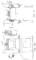
- FIGS. 1a and 1b illustrate a two tiebar index molding machine 10 of the type shown in co-pending U.S. patent application no. 09/070,598, to Galt et al., entitled Tiebar Structure for Injection Molding Machine, filed April 30, 1998, which is incorporated by reference herein.
- the index molding machine 10 includes a base 12, a fixed platen 14, and a movable platen 16 which is movable with respect to the fixed platen 14.
- the movable platen 16 is a two-faced rotary turret block, which is positioned within the movable platen, with pinions in bearings mounted in carriers 18 that slide on the base 12.
- the turret block 16 is rotated or indexed on a central axis 20 so that the faces thereof represent two positions in an injection molding cycle.
- the rotatable turret block 16 is rotatable on a central axis of rotation 20 for rotating a plurality of movable mold halves 36 attached thereto into alignment with a first mold half 32 carried by the fixed platen 14.
- Each movable mold half 36 includes at least one mold core/cavity.
- each movable mold half includes at least one mold core 38 and is matable with the first mold half 32 for forming a mold for forming at least one molded article, with the mold halves being clamped together as will be described hereinafter.
- the first mold half 32 may be joined to the fixed platen 14 in any suitable manner known in the art and may contain one or more mold cores or cavities.
- the first mold half 32 contains one or more mold cavities 34 which together with the mold core(s) 38 form one or more mold cavity spaces 40.
- Parts 50 such as preforms, are molded by injecting plastic material through the mold half 32 from an injection unit (not shown) into the cavity space(s) 40 formed by the closed mold.
- Two tiebars 24 are provided and bolted to the carriers 18, each of which includes an inside stroke cylinder 22, the rod 23 of which is fixed to housing 25 which in turn is bolted to fixed platen 14.
- Each tiebar 24 includes external teeth 26 of a rotating clamp piston 30 with the clamp piston contained in fixed platen 14.
- the clamp piston 30 includes a row of teeth 28 and an adjacent row free from teeth so that on rotation of the clamp piston, the clamp piston teeth 28 alternately engage and disengage the tiebar teeth 26.
- Clamp piston 30 may be rotated by any desired and convenient means (not shown), such as a cylinder means acting on a pin via a slot in housing 25, such as a cylinder bolted to the fixed platen 14 with linkage means connecting the pins together and causing rotation of the pistons 30.
- a pin rotates clamp piston 30 so that clamp piston teeth 28 are disengaged from teeth 26 on tiebars 24.
- High pressure oil is then supplied to the piston end 42 of stroke cylinder 22 via a line (not shown) causing stroke cylinder rod 23 to extend and move carriers 18 and turret block 16 away from the fixed platen 14, thereby opening the mold.
- oil is supplied to the rod side 44 of stroke cylinder 22 via a line (not shown), thereby retracting stroke cylinder rod 23 and closing the clamp until the mold is closed.
- the aforementioned pin (not shown) is then activated by a cylinder (not shown) and linkage means (not shown) to engage clamp piston teeth 28 with tiebar teeth 26.
- High pressure oil is then provided to the clamp piston cylinder 46 causing the clamp pistons to clamp the mold.
- high pressure oil is provided to the mold break cylinder 48 causing clamp piston 30 to act on the back side of tiebar teeth 26 and urge the mold open.
- clamp piston 30 is de-energized and the pin actuated by the aforementioned cylinder and linkage means causes the clamp piston to rotate to disengage clamp piston teeth 28 from tiebar teeth 26 so that stroke cylinder 22 can open the mold.
- the turret block 16 has two faces, each with a mold core plate 36 mounted to it.
- Each mold core plate 36 may be mounted to a respective face of the turret block 16 using any suitable conventional means known in the art.
- each mold core plate 36 has a plurality of core pins 38, equal in number to the number of mold cavities 34 in the first mold half 32.
- a first set A of core pins 38 is aligned with the mold cavities 34 in a molding position, while a second set B of core pins 38 are in a cooling position located 180 degrees from the molding position.
- the parts 50 are partially cooled in a customary manner by cooling circuits (not shown), such as water cooling circuits, in the mold cavity plate 32 and in the core pins 38.
- cooling circuits such as water cooling circuits
- the mold is opened in the manner previously discussed and the molded parts 50 on the first set A of core pins 38 are withdrawn from the mold cavities 34.
- the turret block 16 is then rotated 180 degrees to present the second set B of core pins 38 for molding while the first set A of core pins 38, complete with the molded parts 50 thereon, are presented at the opposite side of the turret block for further cooling.
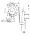
- a device 62 is provided to cool the molded parts and remove them from the core pins 38 when the molded parts are in the cooling position.
- the device 62 includes a frame 64 attached to the carrier 18 or its support.
- a cross beam 66 is attached to the frame 64 so as to be capable of rotation through a 90 degree angle.
- the end of the cross beam 66 remote from the frame 64 is connected to a drive means 68 for rotating the cross beam 66 through said 90 degree rotation.
- the drive means 68 may comprise any suitable drive means known in the art.
- a set of blowing tubes 70 is mounted to a first surface of a head or carrier plate 72 attached to the cross beam 66.
- the blowing tubes 70 are used to direct a cooling fluid, typically air, toward an end of the molded parts 50, while the parts 50 are on the core pins 38. This blowing position is shown in FIG. 2b. Cooling fluid may be supplied to the blowing tubes 70 in any suitable manner known in the art.
- a set of cooling tubes 74 is mounted to a second surface of the head 72. As can be seen from FIG. 2a, the cooling tubes 74 are offset 90 degrees from the blowing tubes 70. The set of cooling tubes 74 are used to facilitate removal of the molded parts 50 from the core pins 38. The cooling tubes 74 assist the removal of the molded parts 50 through the application of a vacuum inside the tubes 74 in a known fashion. For example, a port (not shown) in the bottom of each tube 74 may be connected to a vacuum source (not shown).
- the tubes 74 may be cooled by a fluid, such as chilled water, and remove heat from the parts 50 positioned therein either by convection or conduction. For example, cooling may be achieved by intimate contact between exterior surface of the part and the inside surface of the tube as taught by U.S. Patent No. 4,729,732, which is incorporated by reference herein.
- FIG. 3 - 6 illustrate the sequence of operation of a molding machine in accordance with the present invention.
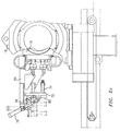
- FIG. 3 shows the clamp closed and the parts 50 being molded on the first core set A.
- FIG. 4 shows the clamp closed for molding on the second core set B while cooling air is being directed from tubes 70 onto the ends of the molded parts 50 on the first core set A.
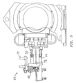
- FIG. 5 shows the cross beam 66 rotated 90 degrees to align the cooling tubes 74 with the parts 50 on the first core set A as the parts are ejected into the tubes 74.
- Ejection of the molded parts 50 from the core pins 38 into tubes 74 is carried out by the provision of ejection means, such as ejection pins/sleeves or an ejection plate, on each mold face 36.
- FIG. 3 shows the clamp closed and the parts 50 being molded on the first core set A.
- FIG. 4 shows the clamp closed for molding on the second core set B while cooling air is being directed from tubes 70 onto the ends of the molded parts 50 on the first
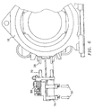
- FIG. 6 shows cross beam 66 rotated 90 degrees in the reverse direction to once again align the blowing tubes 70 with the next set of molded parts while the previous set of parts are ejected from cooling tubes 74.
- Ejection of the cooled parts 50 from the cooling tubes 74 may be effected by discontinuing the vacuum and allowing gravity to cause the parts to drop out of the tubes 74 or by blowing the parts 50 out of the tubes 74 or by mechanical ejection means such as those shown in U.S. Patent No. 5,447,426, which is incorporated by reference herein.
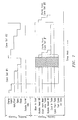
- FIG. 7 shows the sequence of operation for making the molded parts 50.
- the top half of the chart shows the molding process and indicates two identical sequences spaced in time, the first for the first core set A, and the second for the second core set B.
- Each of the sequences starts with the mold closed, as shown in FIG. 1a.
- the injection molding sequence of clamp, inject, hold/cool, and open then follows.
- the index turret block 16 simultaneously begins to rotate 180 degrees to align the second core set for molding while the first core set, with the molded parts 50 on the core pins 38, is aligned to the cooling and removal device 62.
- the rotation is completed during the closing stroke of the turret block 16.
- the bottom half of the chart shows the cooling process and indicates a sequence that overlaps the two molding processes shown in the top half of the chart.
- the ejection and cooling sequence begins as the first core set A with molded parts 50 thereon is aligned to the cooling and removal device 62. Cooling fluid, typically compressed air, is blown from tubes 70 directly onto the ends of the molded parts 50, as they remain cooling on the core pins 38. Thus, during this portion of the sequence, parts 50 are cooled both internally and externally. Then the head 72 is rotated 90 degrees to align the cooling tubes 74 with the molded parts 50 on the core pins 38.
- Cooling fluid typically compressed air
- the ejection system of the mold in combination with the vacuum circuit in the cooling tubes 74 transfers the parts from the core pins 38 to the tubes 74 wherein the parts are immediately cooled on their outer surfaces by their contact with the water cooled tubes, in a known fashion.
- the device 62 is immediately rotated again so that the tubes 74 point downward and the molded parts 50 continue cooling in a vertical orientation to ensure symmetrical cooling and gravitational effects maintaining a distortion-free part.
- the molded parts 50 are held in the tubes 74 by the applied vacuum and continue to cool until just before it is time to rotate the device 62 back to receive the next set of molded parts from the second core set B.
- the cooling time for the complete process optimizes the time the molded parts 50 are cooled, first while in the mold and on the cores and secondly while in the cooling tubes 74. Additional cooling is provided by the air blowing from tubes 70 onto the parts 50 during the shaded portion shown on the chart.
- a lightweight cooling and part removal device mounted on the moving index carrier that first cools the outside of the part 50 by blowing air and subsequently continues to cool the part 50 inside a cooled tube 74 that also removes the part 50 from the mold. Still further, cooling of the part 50 is performed in a vertical orientation inside a cooled tube 74. As a result, the part 50 has improved properties which are beneficial. Using the device of the present invention, time in this vertical orientation is optimized.
- an alternative mechanism can be used to rotate a head 72 containing only cooling tubes 72.
- the head 72 may be attached to a frame 64 mounted to one of the carriers 18 by pin connection 76.
- a piston-cylinder type of actuation unit 78 may be connected to the frame 64.
- the arm 80 of the actuation unit may be connected to a rear portion 82 of the head 72.
- the cooling tubes 74 are aligned with core pins 38 and are removing molded articles therefrom.
- the actuation unit 78 retracts arm 80 and assumes the substantially vertical position shown in dotted lines in the figure.
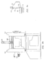
- FIGS. 8a and 8b a second embodiment of the cooling device of the present invention is illustrated.
- blowing tubes 70 have been omitted.
- the cooling device 62' has additional cooling tubes 74 so that multi-position cooling can be effected in a manner similar to that illustrated in U.S. Reissue Patent No. 33,237, which is incorporated by reference herein.
- the device 62' is mounted in position III on the index machine turret carriage 18.
- the device 62' has a single side frame 84 mounted to one of the carriers 18 which contains a cam track profile 86.
- the profile 86 is followed by a cam follower 88 mounted to a movable carrier plate 90 on which are mounted multiple cooling tubes 74.
- the number of cooling tubes 74 on the carrier plate 90 is twice the number of core pins 38 on each face of the turret block 16.
- the actuator 92 may comprise any suitable actuator known in the art such as piston-cylinder unit.
- FIGS. 9a - 9c illustrate an alternative actuation system for moving the cooling device 62' of FIG. 8a so that the carrier plate 90 moves from a vertical orientation to a horizontal orientation.
- the actuator 92 is centrally mounted on a bridge 100 connecting support frames 101 on both sides of the machine 10.
- the actuator 92 in this arrangement, only effects the vertical positioning of the carrier plate 90.
- a separate actuator 102 preferably in the form of a piston-cylinder unit, is provided.
- the actuator 102 moves vertically with the carrier plate and when it reaches the end of its vertical travel, the actuator arm 103 is moved to rotate the carrier plate 90 about the pivot point 105 so that the parts 50 in the cooling tubes 74 is vertically oriented.
- FIGS. 10a and 10b illustrate yet another embodiment of an actuation system for the cooling device 62'.
- two cylinders 104 and 106 are used to translate and rotate the carrier plate.
- the carrier plate 72 containing the cooling tubes 74 is pivotally connected at pivot 108 to the frame 64 which is connected to a support structure on the machine 10.
- the actuator or cylinder 104 may be attached to carrier plate 72 in any suitable manner known in the art and is used to translate the carrier plate 72 with tubes 74 in a vertical direction. This translation may be carried out in any suitable manner known in the art.
- the actuator or cylinder 106 is connected to the carrier plate 72 and is used to rotate the carrier plate 72 about pivot point 108 so that tubes 74 assume a vertical orientation.
- FIGS. 8 - 10 there has been provided in the embodiments of FIGS. 8 - 10, a lightweight, multi-position cooling carrier plate arrangement for attachment to an index carrier that removes parts horizontally from the mold and cools and ejects them in a vertical orientation, while extending cooling time with multiple tubes.
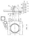
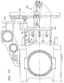
- FIGS. 11-14 there is shown another embodiment of a device for cooling molded parts on a rotary turret block face and for receiving the molded parts from said face and transferring them to a position where certain ones of the molded parts in the receiving means are being cooled and others of the molded parts in the receiving means are being ejected.
- the cooling device 162 includes a take-off plate 200 having a plurality of holders 202 on one of its faces for receiving molded parts 50 from the mold core pins 38 of one of the movable mold halves 36. And a cooling station assembly 204 having a plurality of blowing tubes 70 secured to one of its faces. As shown in FIG.
- the take-off plate 200 and the cooling station assembly 204 are connected to each other via a connecting plate 206.
- the connecting plate 206 is connected to a rear surface 208 of the cooling station assembly 204 by a rigid connection 210.
- the rigid connection 210 may comprise any suitable connection known in the art.
- the connecting plate 206 is connected to a rear surface 212 of the take-off plate 200 via a hinged connection formed by pivotally connected link member 214 and 216.
- the device further includes a support 218.
- the support may be connected to the injection molding machine in any suitable manner known in the art.
- the support 218 may be connected to a support structure (not shown) which is independent of an injection molding machine.
- the support 218 has a linear guide 220 along one surface thereof.
- the linear guide is in the form of a track which extends along an axis C which is substantially perpendicular to the central rotation axis 20 of the turret block 16.
- the connecting plate 206 slides or moves along the linear guide 220.
- the connecting plate may be provided with any suitable means known in the art such a shoes 222 for permitting movement along the linear guide 220.
- the take-off plate 200 is in a position adjacent the face of one of the movable mold halves. Selected ones of the holders 202 are aligned with molded parts 50 on the movable mold half 36. This position of the take-off plate is known as the receiving position. At the same time, the cooling station 204 is positioned in a non-cooling position.
- the molded parts 50 may be transferred to the holders 202 via any suitable means known in the art.
- the movable mold half 36 may be provided with an injection system for transferring the molded parts 50 to the holders 202.
- the holders 202 may have a vacuum system (not shown) for assisting in the transfer of the molded parts 50.
- the vacuum system may comprise any suitable vacuum system known in the art.
- the take-off plate 200 has been moved to a second position wherein selected ones of the molded parts are held for additional cooling in a substantially vertical orientation and others of the molded parts are ejected from selected ones of the holders 202 after a desired cooling cycle has been completed. Further, the cooling station assembly 204 has been moved into a position adjacent a new set of molded articles 50 on the face of a second movable mold half 36. In the position, the cooling tubes 70 are utilized to cause a flow of cooling fluid, typically air, against external surfaces of the molded parts 50. To move the take-off plate 200 from the first receiving position to the second holding/ejecting position, an actuation system 230 is provided.
- the actuation system 230 includes an actuator 236 connected to a pivot arm 234 via a piston arm 240 and a linkage arm 232 connected to a rear surface 212 of the take-off plate and to the pivot arm 234.
- the actuator unit 236 may comprise any suitable actuator means known in the art. For example, it may comprise a piston cylinder type unit. As shown in FIG. 11, when the piston arm 240 has been extended, the take-off plate 200 is in the first receiving position and when the piston arm 240 is retracted, as in FIG. 12, the take-off plate 200 is in its second holding/ejecting position.
- the take-off plate 200 is connected to the connecting plate 206 which is in turn connected to the cooling station assembly 204.
- the connecting plate 206 moves along the linear guide 220 along the axis C. This in turn causes translational movement of the cooling station assembly in a direction parallel to the axis C from the non-cooling position shown in FIG. 11 to the cooling position shown in FIG. 12.
- the molded parts 50 may be ejected using any suitable means known in the art.
- a vacuum system used to hold the molded parts 50 in selected ones of the holders 202 may be shut off, thereby causing gravity to drop the molded parts 50 out of the holders 202.
- the holders 202 may have some form of fluid assist system for ejecting the molded parts 50. After the molded parts 50 have been ejected, selected ones of the holders 202 are vacant.
- the actuation system 230 is actuated after ejection of the molded parts 50 shown in FIG. 12 to return the take-off plate 200 to the first receiving position.
- the receiving position differs from the receiving position shown in FIG. 11 in that a different set of holders 202 is aligned with the molded parts 50 on the mold core pins 38 on the movable mold half 36.
- movement of the take-off plate 200 from the second holding/ejecting position to the receiving position causes the cooling station assembly 204 to move from the cooling position to the non-cooling position.
- This movement is effectuated because the rotation of the take-off plate from the second holding/ejection position to the receiving position causes the connecting plate 206 to move along the linear guide 220 as a result of the linkage connections between the take-off plate 200 and the connecting plate 206.
- the take-off plate 200 is returned to the second holding/ejecting position. Again rotation of the take-off plate 200 from the receiving position to the holding/ejecting position causes the cooling station assembly 204 to move from the non-cooling position to the cooling position so that it is ready to cool the molded parts on the next mold half to be moved into the cooling position. Further, the molded parts 58 which were received by the take-off plate 200 in the previous portion of the molding cycle are now ejected from selected ones of the holders 202.
- actuation unit 236 has been described as being a piston-cylinder unit, it should also be recognized that an electroservo drive system could be used to cause the rotation of the take-off plate 200 between the receiving position and the holding/ejecting position.
- cooling devices of the present invention have been described in the context of removing parts from an injection molding machine having a rotary turret block, it should be apparent that the cooling devices could be used with systems other than index molding machine.
- the cooling devices could be used in a system which has a rotary turret block for receiving molded parts to be cooled from a take-off plate which cooperates with a different form of injection molding machine.
Applications Claiming Priority (4)
| Application Number | Priority Date | Filing Date | Title |
|---|---|---|---|
| US217141 | 1994-03-23 | ||
| US21714198A | 1998-12-21 | 1998-12-21 | |
| US09/263,393 US6113834A (en) | 1998-12-21 | 1999-03-05 | Cooling device attached to index machine |
| US263393 | 1999-03-05 |
Publications (1)
| Publication Number | Publication Date |
|---|---|
| EP1013398A1 true EP1013398A1 (de) | 2000-06-28 |
Family
ID=26911656
Family Applications (1)
| Application Number | Title | Priority Date | Filing Date |
|---|---|---|---|
| EP99121314A Withdrawn EP1013398A1 (de) | 1998-12-21 | 1999-10-26 | Kühlungsvorrichtung befestigt an drehbarer Maschine |
Country Status (4)
| Country | Link |
|---|---|
| US (1) | US6113834A (de) |
| EP (1) | EP1013398A1 (de) |
| JP (2) | JP3649631B2 (de) |
| CA (1) | CA2286926C (de) |
Cited By (2)
| Publication number | Priority date | Publication date | Assignee | Title |
|---|---|---|---|---|
| WO2003097327A1 (en) * | 2002-05-17 | 2003-11-27 | Husky Injection Molding Systems Ltd. | Post mold cooling apparatus and method having rotational and transverse movement |
| US6986653B2 (en) | 2002-05-17 | 2006-01-17 | Husky Injection Molding Systems Ltd. | Post mold cooling apparatus and method having transverse movement |
Families Citing this family (8)
| Publication number | Priority date | Publication date | Assignee | Title |
|---|---|---|---|---|
| US7104780B2 (en) * | 2003-03-21 | 2006-09-12 | Husky Injection Molding Systems Limited | Platen mounted post mold cooling apparatus and method |
| US7052644B2 (en) * | 2003-11-17 | 2006-05-30 | Graham Packaging Pet Technologies, Inc. | Continuous production of molded plastic containers |
| US7632089B2 (en) * | 2004-05-07 | 2009-12-15 | Graham Packaging Pet Technologies, Inc. | Take out and cooling system and method |
| US7252497B2 (en) * | 2005-03-10 | 2007-08-07 | Husky Injection Molding Systems Ltd. | Post-molding molded article conditioning apparatus with a selectively controlled transfer flow structure |
| US7293980B2 (en) * | 2005-03-10 | 2007-11-13 | Husky Injection Molding Systems Ltd. | Porous member for a post-molding molded article conditioning apparatus with an integrally formed cooling structure |
| US7326046B2 (en) * | 2005-03-10 | 2008-02-05 | Husky Injection Molding Systems Ltd. | Multi-layer porous member for a post-molding molded article conditioning apparatus |
| US7789648B2 (en) * | 2007-05-16 | 2010-09-07 | Husky Injection Molding Systems Ltd. | Adjustment device for adjusting a pitch between a take-off plate and a treatment device of a molding system and a method for use thereof |
| JP5430020B2 (ja) * | 2011-11-24 | 2014-02-26 | 精宏機械株式会社 | 米飯冷却装置 |
Citations (5)
| Publication number | Priority date | Publication date | Assignee | Title |
|---|---|---|---|---|
| EP0058947A1 (de) * | 1981-02-23 | 1982-09-01 | The Continental Group, Inc. | Verfahren und Vorrichtung zum Formen von Flaschenvorformlingen |
| USRE33237E (en) * | 1987-03-23 | 1990-06-19 | Husky Injection Molding Systems Ltd. | Apparatus for producing hollow plastic articles |
| EP0794045A1 (de) * | 1996-03-06 | 1997-09-10 | Husky Injection Molding Systems Ltd. | Revolvermaschine zum Formen von Gegenständen |
| EP0876892A2 (de) * | 1997-04-28 | 1998-11-11 | Husky Injection Molding Systems Ltd. | Revolverkopf mit hoher Geschwindigkeit |
| EP0937566A1 (de) * | 1998-02-23 | 1999-08-25 | BM Biraghi S.p.A. | System zum Kühlen und Entfernen von spritzgegossenen Hohlkörpern |
Family Cites Families (3)
| Publication number | Priority date | Publication date | Assignee | Title |
|---|---|---|---|---|
| US33237A (en) * | 1861-09-10 | Window-sash fastener | ||
| US4729732A (en) * | 1985-05-14 | 1988-03-08 | Husky Injection Molding Systems Ltd. | Carrying means for holding and cooling a parison |
| US5728409A (en) * | 1996-03-06 | 1998-03-17 | Husky Injection Molding Systems Ltd. | Turret article molding machine |
-
1999
- 1999-03-05 US US09/263,393 patent/US6113834A/en not_active Expired - Fee Related
- 1999-10-19 CA CA002286926A patent/CA2286926C/en not_active Expired - Fee Related
- 1999-10-26 EP EP99121314A patent/EP1013398A1/de not_active Withdrawn
- 1999-11-01 JP JP31074999A patent/JP3649631B2/ja not_active Expired - Fee Related
-
2004
- 2004-12-08 JP JP2004354939A patent/JP2005104159A/ja not_active Withdrawn
Patent Citations (5)
| Publication number | Priority date | Publication date | Assignee | Title |
|---|---|---|---|---|
| EP0058947A1 (de) * | 1981-02-23 | 1982-09-01 | The Continental Group, Inc. | Verfahren und Vorrichtung zum Formen von Flaschenvorformlingen |
| USRE33237E (en) * | 1987-03-23 | 1990-06-19 | Husky Injection Molding Systems Ltd. | Apparatus for producing hollow plastic articles |
| EP0794045A1 (de) * | 1996-03-06 | 1997-09-10 | Husky Injection Molding Systems Ltd. | Revolvermaschine zum Formen von Gegenständen |
| EP0876892A2 (de) * | 1997-04-28 | 1998-11-11 | Husky Injection Molding Systems Ltd. | Revolverkopf mit hoher Geschwindigkeit |
| EP0937566A1 (de) * | 1998-02-23 | 1999-08-25 | BM Biraghi S.p.A. | System zum Kühlen und Entfernen von spritzgegossenen Hohlkörpern |
Cited By (5)
| Publication number | Priority date | Publication date | Assignee | Title |
|---|---|---|---|---|
| WO2003097327A1 (en) * | 2002-05-17 | 2003-11-27 | Husky Injection Molding Systems Ltd. | Post mold cooling apparatus and method having rotational and transverse movement |
| US6986653B2 (en) | 2002-05-17 | 2006-01-17 | Husky Injection Molding Systems Ltd. | Post mold cooling apparatus and method having transverse movement |
| US7052270B2 (en) | 2002-05-17 | 2006-05-30 | Husky Injection Molding Systems Ltd. | Post mold cooling apparatus |
| US7056465B2 (en) | 2002-05-17 | 2006-06-06 | Husky Injection Molding Systems Ltd. | Post mold cooling apparatus and method having transverse movement |
| CN100404235C (zh) * | 2002-05-17 | 2008-07-23 | 赫斯基注射器成型系统有限公司 | 可以转动和横向运动的出模冷却装置和方法 |
Also Published As
| Publication number | Publication date |
|---|---|
| JP3649631B2 (ja) | 2005-05-18 |
| CA2286926C (en) | 2001-05-01 |
| JP2005104159A (ja) | 2005-04-21 |
| US6113834A (en) | 2000-09-05 |
| CA2286926A1 (en) | 2000-06-21 |
| JP2000176981A (ja) | 2000-06-27 |
Similar Documents
| Publication | Publication Date | Title |
|---|---|---|
| US6059557A (en) | Cooling device attached to index machine | |
| US7056465B2 (en) | Post mold cooling apparatus and method having transverse movement | |
| CA2516480C (en) | Platen mounted post mold cooling apparatus | |
| US6986653B2 (en) | Post mold cooling apparatus and method having transverse movement | |
| US6299431B1 (en) | Cooling apparatus for injection molding machines | |
| US6143225A (en) | Turret cooling block for an index machine | |
| US6113834A (en) | Cooling device attached to index machine | |
| JP2006504557A (ja) | 射出成形機用のサイド・シャットル装置及び方法 | |
| US6848900B2 (en) | Apparatus for handling injection molded preforms | |
| US5744088A (en) | Method and apparatus for manufcturing hollow objects, in particular plastic preforms | |
| EP0992330A2 (de) | An einer Formmaschine mit Revolverkopf befestigtes Kühlungsgerät | |
| WO1985000554A1 (en) | Label transferring apparatus for blow molding machines | |
| US20080265467A1 (en) | Molding Structure Sub-Assemblies for a Mold and Method of Use |
Legal Events
| Date | Code | Title | Description |
|---|---|---|---|
| PUAI | Public reference made under article 153(3) epc to a published international application that has entered the european phase |
Free format text: ORIGINAL CODE: 0009012 |
|
| AK | Designated contracting states |
Kind code of ref document: A1 Designated state(s): AT BE CH CY DE DK ES FI FR GB GR IE IT LI LU MC NL PT SE |
|
| AX | Request for extension of the european patent |
Free format text: AL;LT;LV;MK;RO;SI |
|
| 17P | Request for examination filed |
Effective date: 20001021 |
|
| AKX | Designation fees paid |
Free format text: AT BE CH CY DE DK ES FI FR GB GR IE IT LI LU MC NL PT SE |
|
| 17Q | First examination report despatched |
Effective date: 20010529 |
|
| STAA | Information on the status of an ep patent application or granted ep patent |
Free format text: STATUS: THE APPLICATION IS DEEMED TO BE WITHDRAWN |
|
| 18D | Application deemed to be withdrawn |
Effective date: 20011009 |