EP1013348A1 - A screenless vibrator separator - Google Patents
A screenless vibrator separator Download PDFInfo
- Publication number
- EP1013348A1 EP1013348A1 EP97902148A EP97902148A EP1013348A1 EP 1013348 A1 EP1013348 A1 EP 1013348A1 EP 97902148 A EP97902148 A EP 97902148A EP 97902148 A EP97902148 A EP 97902148A EP 1013348 A1 EP1013348 A1 EP 1013348A1
- Authority
- EP
- European Patent Office
- Prior art keywords
- trough
- blade
- material trough
- screenless
- vibrator
- Prior art date
- Legal status (The legal status is an assumption and is not a legal conclusion. Google has not performed a legal analysis and makes no representation as to the accuracy of the status listed.)
- Granted
Links
Images

Classifications
-
- B—PERFORMING OPERATIONS; TRANSPORTING
- B07—SEPARATING SOLIDS FROM SOLIDS; SORTING
- B07B—SEPARATING SOLIDS FROM SOLIDS BY SIEVING, SCREENING, SIFTING OR BY USING GAS CURRENTS; SEPARATING BY OTHER DRY METHODS APPLICABLE TO BULK MATERIAL, e.g. LOOSE ARTICLES FIT TO BE HANDLED LIKE BULK MATERIAL
- B07B13/00—Grading or sorting solid materials by dry methods, not otherwise provided for; Sorting articles otherwise than by indirectly controlled devices
- B07B13/14—Details or accessories
- B07B13/16—Feed or discharge arrangements
-
- B—PERFORMING OPERATIONS; TRANSPORTING
- B07—SEPARATING SOLIDS FROM SOLIDS; SORTING
- B07B—SEPARATING SOLIDS FROM SOLIDS BY SIEVING, SCREENING, SIFTING OR BY USING GAS CURRENTS; SEPARATING BY OTHER DRY METHODS APPLICABLE TO BULK MATERIAL, e.g. LOOSE ARTICLES FIT TO BE HANDLED LIKE BULK MATERIAL
- B07B13/00—Grading or sorting solid materials by dry methods, not otherwise provided for; Sorting articles otherwise than by indirectly controlled devices
- B07B13/04—Grading or sorting solid materials by dry methods, not otherwise provided for; Sorting articles otherwise than by indirectly controlled devices according to size
-
- B—PERFORMING OPERATIONS; TRANSPORTING
- B07—SEPARATING SOLIDS FROM SOLIDS; SORTING
- B07B—SEPARATING SOLIDS FROM SOLIDS BY SIEVING, SCREENING, SIFTING OR BY USING GAS CURRENTS; SEPARATING BY OTHER DRY METHODS APPLICABLE TO BULK MATERIAL, e.g. LOOSE ARTICLES FIT TO BE HANDLED LIKE BULK MATERIAL
- B07B13/00—Grading or sorting solid materials by dry methods, not otherwise provided for; Sorting articles otherwise than by indirectly controlled devices
- B07B13/08—Grading or sorting solid materials by dry methods, not otherwise provided for; Sorting articles otherwise than by indirectly controlled devices according to weight
Definitions
- the present invention relates to a screening plant for unequal particles of the solid, especially to a screenless vibratory separator.
- screening device with mesh or mesh screen involves the devices with rolling axis screen, cylindric screen vibratory screen etc.
- the cylindric screen is a metal cylinder provided with several apertures in its circumference, which is driven by a motor, the particles are loaded within a cylinder, the particles having diameters which are smaller than the screen mesh will be leaked out therefrom when the cylinder is driven by the motor;
- the vibratory screen consists of a vibratile material trough and mesh screen, the particles in the material trough will fall to the mesh screen with vibrating as the particles in the trough are vibrated, the material with particle-size which is smaller than the diameter of mesh are leaked out from the screen mesh so as to obtain the separation of the material.
- a screening device without mesh such as jiggers, rocking bed and so on.
- the advantage of the jiggers is in that the mineral concentrate with coarse granule can be obtained at an early date, the oversmash of mineral is then reduced, and the capacity production per unit area is large.
- the type of the jigger is much, its disadvantage is also various, such as the occupied area is large, the mineral concentrate can not be removed, examination and repair are not convenient, the body of the jigger is heavy, there are many production accidents, the handling capacity per unit area is lower and so on.
- the vibratory feeder and conveyer which are available for reference as prior art, the feature of the vibratory feeder is high amplitude and low frequency; the feature of the conveyer is low amplitude and high frequency. They have the function of vibration and conveyance, but without the function of screening particles.
- the feature of the rocking bed is high rich mineral ratio which can be over 100 times, with which the final mineral concentrate is obtained, the final tails can be diverged at same time
- the rocking bed can be more effective than the jigger to handle the finer particles, its suitable mineral granularity is below 3mm.
- the mineral particles on the bed are distributed in the form of segment when the mineral is dressed by the rocking bed, so that the multiple products can be received according to the requirement, it is advantageous to further handle respectively the useful minerals and to increase the metal recovery ratio.
- the greatest disadvantage of the rocking bed is high unit occupied area and low capacity production.
- the object of the present invention is to overcome the deficiencies and disadvantages which are present in above-mentioned screening device with mesh screen and screenless separator (jigger, rocking bed), to provide a screenless vibratory separator, the structure of such separator is simple and suitable for separating material with all granularity, at same time, the separating capacity in unit time is large, which is adapted for the industrialized separation production of a large batch material; the raw material and energy are saved; and the separating efficiency is high, with good quality.
- the screenless vibratory separator provided by the present invention consists of a material trough, an one-freedom frame, a vibrator, a blade and an adjuster for the blade.
- the material trough is an open flat bottom trough, there is a material outlet in the bottom of output, the material trough is supported by two or more groups of one-freedom frame in the form of one-freedom (unidirectional) swing;
- the one-freedom frame consists of two or more groups of main supports placed parallelly and aslant, with the same amount and one or more elastic shock-absorb supports.
- the upper part and lower part of each main support are respectively connected axially with the material trough and the base by horizontal placed axes. All main supports are according to connecting axes of the trough as fulcrums and form the same acute angle with the bottom for the output of material trough.
- At the upper part each group of the main supports joins the same amount of parallel placed elastic shock-absorb supports by way of axis, whose lower part is fixed on the base.
- the angle included between the main support and the shock-absorb support is 85° - 95° , and the material trough is jointly upheld by the supports.
- the elastic shock-absorb support is elastic support, which can also produce a reaction to the material trough for strengthening vibratory effect and can relieve harmful shocks causing by the material trough against the base during the operation, in order to increase the equipment life, the material trough is made to form an effective vibration with monofreedom (unidirection), in addition to the act together with the main support for supporting the material trough.
- the vibrators are mounted on the material trough in pairs and symmetrical to its transversal or longitudinal central line.
- each vibrator The frequency of each vibrator is same, each pair of vibrator rotates in the opposing direction, the difference of phase angle is 180° , the force of transversal movement is counterbalanced in vibrating, which makes the material trough vibrate effectively with one-freedom towards the front-top part of its outlet and the noise is reduced.
- the blade consists of one or more plate oblique to the material trough, its upper end is pivoted with the corresponding horizontal axes at the outlet of material trough, the angle included between blade and bottom of material trough is an acute angle which is generally 1-10° . Every horizontal axis can be moved vertically and positioned at the outlet of material trough to adjust up-and-down position for the underside of the blade.
- One or more adjusters for the blade are also provided in the invention, which can adjust the angle included between the blade and the bottom of the material trough, each adjuster for the blade can adjust the gap between the corresponding blade and the material outlet at the bottom of the material trough, through adjusting the angle included between blade and bottom of material trough respectively.
- vibrators When operating, vibrators keep the particles in the material trough regular vibrating and are in the form of stratification according to granularity. smaller particles are in the lower layers and bigger particle are in the upper layers.
- the adjusters for the blades or moving and positioning the up-and-down position of the horizontal axes the undersides of one or more blades are adjusted to a proper outlet for a desired granularity, at this time, the gap between the lowest layer of blade and the material outlet for the bottom of material trough is just adapted for discharging the particles of the lower layer.
- the particles of the lower layer are discharged from the material outlet with the vibration of the material trough.
- the particles with various granularity from other layers continue to move towards the output direction and climb up from the corresponding blade, then roll out of the trough during vibrating, the screening or separating work of particles with various granularity is then completed.
- An interior underlayer or a liner is mounted in the material trough to enhance the screening effect and improve the tear-proof and corrosion-proof performance.
- a vibratory material trough shown in Fig. 1 instead of traditional structure with mesh, particles can vibrate at a certain type, amplitude and frequency, big particles are rising up and small particles are sinking down.
- the adjuster draw the blade up to let small particles drain out through material outlet for the bottom of material trough and big particles move towards the output of trough, then climb up from the upside of blade and roll out of the trough, the vibrating separation of various particles is then completed.
- the invention is adapted for such fields as fertilizer, grain processing, ore and metallurgy, especially, the best separating effect is obtained for the dry materials with same gravity.
- An interior underlayer is installed according to the physical and chemical requirements of different material, which can prevent the material trough from corrosion and increase tear-and-wear capability of trough.
- the screenless vibratory separator provided by the present invention is well adapted for the industrializing production of mass classification of material, e.g., ore dressing, separating particles in grain processing and screening coal at coal-field, a screening effect can be up to 180 tons per hour.
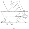
- Fig.1 indicates that the material trough 1 is a flat bottom trough.
- a material outlet 8 is provided at the bottom of trough near the output, which is covered by the blade 6 at its upside.
- One side of the blade 6 is pivoted with the horizontal axis 7 and extends out of the material trough; the other relies on the trough.
- One end of the adjuster 4 for the blade is installed in the middle under the blade 6, the other end joins a top bar (not shown).
- the one-freedom main support 2 and the elastic shock-absorb support 3 hold up the body of the material trough 1.
- the elastic shock-absorb support 3 counterbalance the harmful shocks of the vibrator 5.
- each blade 6 pivoted with the horizontal axes perpendicular to the output of trough separately, form a blade group, and each blade 6 is adjusted same one or more adjuster 4, material with more than two levels of granularity can be classified by such method at the same time.
- Each blade forms its own angle to the bottom of trough 1.
- the angle of an upper blade is normally 1° to 3° bigger than that of a lower one.
- Adjusting the mutual installing position of the one-freedom support 2 the elastic shock-absorb support 3 and the vibrator 5 can make material trough 1 produce variant types of vibration, increase the screening efficiency.
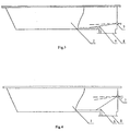
- Fig.2 is a schematic view showing the structural of a screenless vibratory separator with vibrators 5 symmetrically installed above the material trough 1.
- the blade and the bottom of the trough form an acute angle and the horizontal axis can move upward vertically at the resting state.
- Fig.3 shows only a view wherein the horizontal axis is vertically at the lowest position of the output for trough.
- the angle of the blade is an acute one when the blade covers completely the material outlet. Once the blade 6 opens, its angle is 9° to 0° , which is the optimal working angle for the blade.
- Fig.4 shows only a view wherein the horizontal axis is vertically at an arbitrary position.
- the angle of the blade is larger than or equal the working angle,when the blade covers completely the material outlet, the angle is still in 9° to 0° when the blade in working state.
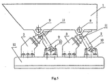
- Fig.5 is a schematic view showing the structural in which the one-freedom frames uphold the material trough 1.
- the screenless vibratory separator provided by the invention includes two groups of one-freedom frames, each of which consists of a parallel oblique main support 2 pivoted on both ends the axis 9, and an elastic shock-absorb support 3 intercrossing perpendicularly to and joining to the main support 2 by the axis 11.
- the underside of the main support 2 is connected with the base 12 by the axis 10.
- the underside of the elastic shock-absorb support 3 is fixed to the base 12.
- Both groups of the one-freedom frames support the material trough by axis 9 respectively.
- vibrator 5 starts to shake the whole trough, makes the particles stratified, bigger particles are rising up and smaller particles are sinking down. After vibrating for an certain time, the stratified particles move towards the output of trough, then climb up from the corresponding blade and roll out of the trough 1. With the act of the top bar, the adjuster for the blade 4 draws the blade up, makes the angle included between the lower blade and the outlet of particles just adapt for discharge small particles through the outlet 8 for bottom of trough. The vibrating separation of particles is then completed.
- This invention takes on especially the best separating effect for dry material with the same gravity. It can be applied to such fields as fertilizer, grain processing, ore and metallurgy.
Abstract
Description
- The present invention relates to a screening plant for unequal particles of the solid, especially to a screenless vibratory separator.
- The solids of unequal particles are usually separated by screening device with mesh or mesh screen. Such screening device with mesh or mesh screen involves the devices with rolling axis screen, cylindric screen vibratory screen etc.
- The cylindric screen is a metal cylinder provided with several apertures in its circumference, which is driven by a motor, the particles are loaded within a cylinder, the particles having diameters which are smaller than the screen mesh will be leaked out therefrom when the cylinder is driven by the motor; the vibratory screen consists of a vibratile material trough and mesh screen, the particles in the material trough will fall to the mesh screen with vibrating as the particles in the trough are vibrated, the material with particle-size which is smaller than the diameter of mesh are leaked out from the screen mesh so as to obtain the separation of the material.
- Above-mentioned screening devices whether what is the kind involve the screen with mesh, in use, the phenomenon of mesh blocked by the particles is occurred usually and the screening efficiency is substantially influenced. Moreover, the aperture of each screen mesh is constant the difference between various meshes is larger, it is impossible of that the screening is met for all material with granule, so as the limitation in use is also larger.
- In the mineral-dressing industry, a screening device without mesh, such as jiggers, rocking bed and so on, is commonly used. The advantage of the jiggers is in that the mineral concentrate with coarse granule can be obtained at an early date, the oversmash of mineral is then reduced, and the capacity production per unit area is large. The type of the jigger is much, its disadvantage is also various, such as the occupied area is large, the mineral concentrate can not be removed, examination and repair are not convenient, the body of the jigger is heavy, there are many production accidents, the handling capacity per unit area is lower and so on.
- Furthermore, the vibratory feeder and conveyer which are available for reference as prior art, the feature of the vibratory feeder is high amplitude and low frequency; the feature of the conveyer is low amplitude and high frequency. They have the function of vibration and conveyance, but without the function of screening particles. The feature of the rocking bed is high rich mineral ratio which can be over 100 times, with which the final mineral concentrate is obtained, the final tails can be diverged at same time The rocking bed can be more effective than the jigger to handle the finer particles, its suitable mineral granularity is below 3mm. The mineral particles on the bed are distributed in the form of segment when the mineral is dressed by the rocking bed, so that the multiple products can be received according to the requirement, it is advantageous to further handle respectively the useful minerals and to increase the metal recovery ratio. The greatest disadvantage of the rocking bed is high unit occupied area and low capacity production.
- Moreover, it should be explained that for the screenless separator such as above-mentioned jiggers and rocking beds, however, there is no problem of the mesh blocked, but the screening material must be completed in the water, namely wet-screening, the material with finer granule are flushed out by means of the stream and the screening object is then obtained, it makes the disadvantage not only in occupying large area, heavy and complicated equipment, but also in waste water resources, large dissipation of energy and high cost etc.
- The object of the present invention is to overcome the deficiencies and disadvantages which are present in above-mentioned screening device with mesh screen and screenless separator (jigger, rocking bed), to provide a screenless vibratory separator, the structure of such separator is simple and suitable for separating material with all granularity, at same time, the separating capacity in unit time is large, which is adapted for the industrialized separation production of a large batch material; the raw material and energy are saved; and the separating efficiency is high, with good quality.
- The screenless vibratory separator provided by the present invention consists of a material trough, an one-freedom frame, a vibrator, a blade and an adjuster for the blade.
- The material trough is an open flat bottom trough, there is a material outlet in the bottom of output, the material trough is supported by two or more groups of one-freedom frame in the form of one-freedom (unidirectional) swing;
- The one-freedom frame consists of two or more groups of main supports placed parallelly and aslant, with the same amount and one or more elastic shock-absorb supports. The upper part and lower part of each main support are respectively connected axially with the material trough and the base by horizontal placed axes. All main supports are according to connecting axes of the trough as fulcrums and form the same acute angle with the bottom for the output of material trough. At the upper part each group of the main supports joins the same amount of parallel placed elastic shock-absorb supports by way of axis, whose lower part is fixed on the base. The angle included between the main support and the shock-absorb support is 85° - 95° , and the material trough is jointly upheld by the supports. The elastic shock-absorb support is elastic support, which can also produce a reaction to the material trough for strengthening vibratory effect and can relieve harmful shocks causing by the material trough against the base during the operation, in order to increase the equipment life, the material trough is made to form an effective vibration with monofreedom (unidirection), in addition to the act together with the main support for supporting the material trough. The vibrators are mounted on the material trough in pairs and symmetrical to its transversal or longitudinal central line. The frequency of each vibrator is same, each pair of vibrator rotates in the opposing direction, the difference of phase angle is 180° , the force of transversal movement is counterbalanced in vibrating, which makes the material trough vibrate effectively with one-freedom towards the front-top part of its outlet and the noise is reduced. The blade consists of one or more plate oblique to the material trough, its upper end is pivoted with the corresponding horizontal axes at the outlet of material trough, the angle included between blade and bottom of material trough is an acute angle which is generally 1-10° . Every horizontal axis can be moved vertically and positioned at the outlet of material trough to adjust up-and-down position for the underside of the blade. One or more adjusters for the blade are also provided in the invention, which can adjust the angle included between the blade and the bottom of the material trough, each adjuster for the blade can adjust the gap between the corresponding blade and the material outlet at the bottom of the material trough, through adjusting the angle included between blade and bottom of material trough respectively.
- When operating, vibrators keep the particles in the material trough regular vibrating and are in the form of stratification according to granularity. smaller particles are in the lower layers and bigger particle are in the upper layers. By means of the adjusters for the blades or moving and positioning the up-and-down position of the horizontal axes, the undersides of one or more blades are adjusted to a proper outlet for a desired granularity, at this time, the gap between the lowest layer of blade and the material outlet for the bottom of material trough is just adapted for discharging the particles of the lower layer. The particles of the lower layer are discharged from the material outlet with the vibration of the material trough. And the particles with various granularity from other layers continue to move towards the output direction and climb up from the corresponding blade, then roll out of the trough during vibrating, the screening or separating work of particles with various granularity is then completed.
- An interior underlayer or a liner is mounted in the material trough to enhance the screening effect and improve the tear-proof and corrosion-proof performance.
- With a vibratory material trough shown in Fig. 1 instead of traditional structure with mesh, particles can vibrate at a certain type, amplitude and frequency, big particles are rising up and small particles are sinking down. After vibrating for a certain time, the adjuster draw the blade up to let small particles drain out through material outlet for the bottom of material trough and big particles move towards the output of trough, then climb up from the upside of blade and roll out of the trough, the vibrating separation of various particles is then completed. The invention is adapted for such fields as fertilizer, grain processing, ore and metallurgy, especially, the best separating effect is obtained for the dry materials with same gravity. An interior underlayer is installed according to the physical and chemical requirements of different material, which can prevent the material trough from corrosion and increase tear-and-wear capability of trough.
- The screenless vibratory separator provided by the present invention, especially the type of multi-blade, is well adapted for the industrializing production of mass classification of material, e.g., ore dressing, separating particles in grain processing and screening coal at coal-field, a screening effect can be up to 180 tons per hour.
- The Present invention will be described in detail with reference to drawings and embodiments as below.
-
- Fig.1 is a schematic view showing the structural of a screenless vibratory separator with vibrators symmetrically mounted on the two sides of the material trough.
- Fig.2 is a schematic view showing the structural of a screenless vibratory separator with vibrators symmetrically installed above the material trough.
- Fig.3 is a schematic view showing the angle of the blade in the material trough.
- Fig.4 is a schematic view showing the angle of the blade in the material trough when the horizontal axis moves upward.
- Fig.5 is a schematic view showing the structural with which the one-freedom frames uphold the material trough.
-
- Wherein:
1- material trough 2- main support 3- elastic shock-absorb support 4- adjuster for the blade 5- vibrator 6- blade 7- horizontal axis 8- outlet for small particles 9,10,11- axis 12- base - Fig.1 indicates that the
material trough 1 is a flat bottom trough. Amaterial outlet 8 is provided at the bottom of trough near the output, which is covered by theblade 6 at its upside. One side of theblade 6 is pivoted with thehorizontal axis 7 and extends out of the material trough; the other relies on the trough. One end of theadjuster 4 for the blade is installed in the middle under theblade 6, the other end joins a top bar (not shown). The one-freedommain support 2 and the elastic shock-absorb support 3 hold up the body of thematerial trough 1. The elastic shock-absorb support 3 counterbalance the harmful shocks of thevibrator 5. - The upper ends of
several blades 6, pivoted with the horizontal axes perpendicular to the output of trough separately, form a blade group, and eachblade 6 is adjusted same one ormore adjuster 4, material with more than two levels of granularity can be classified by such method at the same time. Each blade forms its own angle to the bottom oftrough 1. The angle of an upper blade is normally 1° to 3° bigger than that of a lower one. - Adjusting the mutual installing position of the one-
freedom support 2 the elastic shock-absorb support 3 and thevibrator 5 can makematerial trough 1 produce variant types of vibration, increase the screening efficiency. - Fig.2 is a schematic view showing the structural of a screenless vibratory separator with
vibrators 5 symmetrically installed above thematerial trough 1. The blade and the bottom of the trough form an acute angle and the horizontal axis can move upward vertically at the resting state. - Fig.3 shows only a view wherein the horizontal axis is vertically at the lowest position of the output for trough. The angle of the blade is an acute one when the blade covers completely the material outlet. Once the
blade 6 opens, its angle is 9° to 0° , which is the optimal working angle for the blade. - Fig.4 shows only a view wherein the horizontal axis is vertically at an arbitrary position. The angle of the blade is larger than or equal the working angle,when the blade covers completely the material outlet, the angle is still in 9° to 0° when the blade in working state.
- Fig.5 is a schematic view showing the structural in which the one-freedom frames uphold the
material trough 1. As shown in Fig.5, the screenless vibratory separator provided by the invention includes two groups of one-freedom frames, each of which consists of a parallel obliquemain support 2 pivoted on both ends theaxis 9, and an elastic shock-absorbsupport 3 intercrossing perpendicularly to and joining to themain support 2 by theaxis 11. The underside of themain support 2 is connected with the base 12 by theaxis 10. The underside of the elastic shock-absorbsupport 3 is fixed to thebase 12. Both groups of the one-freedom frames support the material trough byaxis 9 respectively. Once power is on,vibrator 5 starts to shake the whole trough, makes the particles stratified, bigger particles are rising up and smaller particles are sinking down. After vibrating for an certain time, the stratified particles move towards the output of trough, then climb up from the corresponding blade and roll out of thetrough 1. With the act of the top bar, the adjuster for theblade 4 draws the blade up, makes the angle included between the lower blade and the outlet of particles just adapt for discharge small particles through theoutlet 8 for bottom of trough. The vibrating separation of particles is then completed. This invention takes on especially the best separating effect for dry material with the same gravity. It can be applied to such fields as fertilizer, grain processing, ore and metallurgy.
Claims (5)
- A screenless vibratory separator, characterized in that the separator consists of a material trough, a one-freedom frame, a vibrator, a blade and an adjuster for the blade;the material trough is an open flat bottom trough, there is a material outlet in the bottom of output, the material trough is supported by two groups or more groups of one-freedom frame in the form of one-freedom (unidirectional) swing;the vibrators are mounted on the material trough in pair and symmetrically to its transversal or longitudinal central line, the motor for each pair of vibrator is rotating in the opposing direction, each vibrator is vibrating with same frequency, difference of the phase angles is 180° ;one or several blades are flat plate inclined to the material trough, the upper end is pivoted on the respective horizontal axis of the outlet for material trough, the lower end forms respectively an acute angle with the bottom of the material trough;the adjuster for blade is connected with the blade, the adjustable blade forms and angle with the bottom of material trough.
- The screenless vibratory separator according to claim 1, characterized in that said one-freedom frame includes two or more groups of the same amount of parallel oblique main supports and one or more elastic shock-absorb supports, the upper and lower part of each main support are respectively connected with the material trough and the base by horizontal axes as fulcrums, main supports are according to connecting axes of trough as fulcrums and form the same acute angle with the bottom for the output of trough, at the upper part each group of the main supports joins the same amount of parallel placed elastic shock-absorb supports by way of axis, whose lower part is fixed on the base, the angle included between main support and the shock-absorb support is 85° - 95° .
- The screenless vibratory separator according to claim 1, characterized in that said horizontal axis pivoted with the upper end of blade can move vertically and be positioned.
- The screenless vibratory separator according to claim 1, characterized in that an underlayer made of erosion-resistance and tear-and-wear-resistance materials is mounted in said material trough.
- The screenless vibratory separator according to claim 1, characterized in that the mutual position of said main support, elastic shock-absorb support and vibrator is adjustable.
Applications Claiming Priority (3)
| Application Number | Priority Date | Filing Date | Title |
|---|---|---|---|
| CN97100203 | 1997-01-02 | ||
| CN97100203 | 1997-01-02 | ||
| PCT/CN1997/000007 WO1998029202A1 (en) | 1997-01-02 | 1997-01-28 | A screenless vibrator separator |
Publications (3)
| Publication Number | Publication Date |
|---|---|
| EP1013348A1 true EP1013348A1 (en) | 2000-06-28 |
| EP1013348A4 EP1013348A4 (en) | 2000-09-06 |
| EP1013348B1 EP1013348B1 (en) | 2002-03-27 |
Family
ID=5164867
Family Applications (1)
| Application Number | Title | Priority Date | Filing Date |
|---|---|---|---|
| EP97902148A Expired - Lifetime EP1013348B1 (en) | 1997-01-02 | 1997-01-28 | A screenless vibrator separator |
Country Status (8)
| Country | Link |
|---|---|
| US (1) | US6234319B1 (en) |
| EP (1) | EP1013348B1 (en) |
| JP (1) | JP2001518004A (en) |
| AU (1) | AU746748B2 (en) |
| CA (1) | CA2276451A1 (en) |
| DE (1) | DE69711462T2 (en) |
| RU (1) | RU2174877C2 (en) |
| WO (1) | WO1998029202A1 (en) |
Cited By (1)
| Publication number | Priority date | Publication date | Assignee | Title |
|---|---|---|---|---|
| WO2005025762A1 (en) | 2003-09-17 | 2005-03-24 | Rakennusliike Rantasalmen Rakentajat Oy | Sorting device and method |
Families Citing this family (6)
| Publication number | Priority date | Publication date | Assignee | Title |
|---|---|---|---|---|
| US6907996B1 (en) * | 2000-07-20 | 2005-06-21 | Arthur P. Fraas | Application of complex-mode vibration-fluidized beds to the separation of granular materials of different density |
| CA2416724C (en) * | 2000-07-24 | 2007-10-02 | Burkit Mainin | Jigging machine |
| CA2442570C (en) * | 2001-04-06 | 2008-06-10 | Burkit Mainin | Mineral processing device |
| RU2564715C1 (en) * | 2014-05-20 | 2015-10-10 | федеральное государственное бюджетное образовательное учреждение высшего профессионального образования "Южно-Российский государственный политехнический университет (НПИ) имени М.И. Платова" | Screenless device for pre-sizing of coal and ores |
| CN107626578A (en) * | 2017-11-10 | 2018-01-26 | 金陵科技学院 | A kind of sandstone full rotation type screening plant |
| CN108525996A (en) * | 2018-05-21 | 2018-09-14 | 巢湖学院 | A kind of two degrees of freedom high-efficiency vibration screening mechanism |
Family Cites Families (7)
| Publication number | Priority date | Publication date | Assignee | Title |
|---|---|---|---|---|
| US1548536A (en) * | 1925-08-04 | Comcent-batob | ||
| DE63063C (en) * | V. TILL in Bruck a. Mur | A device for sorting small-grain substances such as grain, semolina and the like | ||
| US836553A (en) * | 1905-12-07 | 1906-11-20 | Adam J Bauer | Ore-separator. |
| US3003635A (en) * | 1959-08-07 | 1961-10-10 | Pettibone Mulliken Corp | Shake screen with phasing links and air cushions |
| US3472379A (en) * | 1967-06-12 | 1969-10-14 | Uniroyal Inc | Separation process |
| DE3716664A1 (en) * | 1987-05-19 | 1988-12-01 | Buehler Miag Gmbh | SELECTION MACHINE FOR GRAINY GOODS |
| DE3721436A1 (en) | 1987-06-29 | 1989-01-12 | Iss Ges Fuer Schweissen Und Sc | Method for the production of a composite screen plate and a composite screen plate |
-
1997
- 1997-01-28 JP JP52953098A patent/JP2001518004A/en not_active Ceased
- 1997-01-28 US US09/331,585 patent/US6234319B1/en not_active Expired - Fee Related
- 1997-01-28 WO PCT/CN1997/000007 patent/WO1998029202A1/en active IP Right Grant
- 1997-01-28 RU RU99116368/03A patent/RU2174877C2/en active
- 1997-01-28 CA CA002276451A patent/CA2276451A1/en not_active Abandoned
- 1997-01-28 DE DE69711462T patent/DE69711462T2/en not_active Expired - Fee Related
- 1997-01-28 AU AU15885/97A patent/AU746748B2/en not_active Ceased
- 1997-01-28 EP EP97902148A patent/EP1013348B1/en not_active Expired - Lifetime
Non-Patent Citations (2)
| Title |
|---|
| No further relevant documents disclosed * |
| See also references of WO9829202A1 * |
Cited By (2)
| Publication number | Priority date | Publication date | Assignee | Title |
|---|---|---|---|---|
| WO2005025762A1 (en) | 2003-09-17 | 2005-03-24 | Rakennusliike Rantasalmen Rakentajat Oy | Sorting device and method |
| US7866484B2 (en) | 2003-09-17 | 2011-01-11 | Rantasalmen Scel Oy | Sorting device and method |
Also Published As
| Publication number | Publication date |
|---|---|
| EP1013348A4 (en) | 2000-09-06 |
| DE69711462D1 (en) | 2002-05-02 |
| EP1013348B1 (en) | 2002-03-27 |
| DE69711462T2 (en) | 2002-11-14 |
| JP2001518004A (en) | 2001-10-09 |
| RU2174877C2 (en) | 2001-10-20 |
| AU746748B2 (en) | 2002-05-02 |
| CA2276451A1 (en) | 1998-07-09 |
| US6234319B1 (en) | 2001-05-22 |
| WO1998029202A1 (en) | 1998-07-09 |
| AU1588597A (en) | 1998-07-31 |
Similar Documents
| Publication | Publication Date | Title |
|---|---|---|
| CN107470136A (en) | One kind becomes amplitude equal thick screen | |
| KR20200135380A (en) | Method and apparatus for grading and cleaning sand | |
| EP1013348B1 (en) | A screenless vibrator separator | |
| US4444656A (en) | Classifying apparatus and methods | |
| CN202683454U (en) | Rotary screw roller type vibrating screening machine | |
| US5397002A (en) | Variable control screen apparatus | |
| CN207401729U (en) | A kind of change amplitude equal thick screen | |
| CN216779432U (en) | Sand screening device for ready-mixed mortar | |
| CN214160463U (en) | Can promote sand sieving machine shale shaker hopper of separation effect | |
| CN210847099U (en) | Double-shaft rod type feeding machine | |
| CN109332332A (en) | A kind of sand washer that difference granularity quickly dispenses | |
| CN1242722A (en) | Screenless vibrator separator | |
| CN211056013U (en) | A vibrating conveyor for production of granular pesticide midbody | |
| CN203899910U (en) | Inclination angle-variable full amplitude bearing elliptical orbit high-frequency vibrating screen | |
| CN102873021A (en) | Roller-type rotary spiral vibrating sieving machine | |
| CN213996685U (en) | Screening platform is used in seasoning processing | |
| CN101402089A (en) | Vibration non-mesh screening machine | |
| CN102873022B (en) | Rotary spiral roller-type vibrating sieving machine | |
| CN210619316U (en) | Novel grit feed bin down | |
| JP2607841B2 (en) | Crushing machine | |
| US1136293A (en) | Process of and apparatus for classifying comminuted material. | |
| CN2182684Y (en) | High frequency machinery vibration type sieve | |
| CN212190067U (en) | Plane rotary screen | |
| CN215964690U (en) | Multistage screening plant of mine barren rock stone sediment | |
| CN218554757U (en) | Automatic high-frequency vibration material sieve |
Legal Events
| Date | Code | Title | Description |
|---|---|---|---|
| PUAI | Public reference made under article 153(3) epc to a published international application that has entered the european phase |
Free format text: ORIGINAL CODE: 0009012 |
|
| 17P | Request for examination filed |
Effective date: 19990730 |
|
| AK | Designated contracting states |
Kind code of ref document: A1 Designated state(s): DE FR GB IT |
|
| A4 | Supplementary search report drawn up and despatched |
Effective date: 20000724 |
|
| AK | Designated contracting states |
Kind code of ref document: A4 Designated state(s): DE FR GB IT |
|
| GRAG | Despatch of communication of intention to grant |
Free format text: ORIGINAL CODE: EPIDOS AGRA |
|
| 17Q | First examination report despatched |
Effective date: 20010720 |
|
| GRAG | Despatch of communication of intention to grant |
Free format text: ORIGINAL CODE: EPIDOS AGRA |
|
| GRAH | Despatch of communication of intention to grant a patent |
Free format text: ORIGINAL CODE: EPIDOS IGRA |
|
| REG | Reference to a national code |
Ref country code: GB Ref legal event code: IF02 |
|
| GRAH | Despatch of communication of intention to grant a patent |
Free format text: ORIGINAL CODE: EPIDOS IGRA |
|
| GRAA | (expected) grant |
Free format text: ORIGINAL CODE: 0009210 |
|
| AK | Designated contracting states |
Kind code of ref document: B1 Designated state(s): DE FR GB IT |
|
| REF | Corresponds to: |
Ref document number: 69711462 Country of ref document: DE Date of ref document: 20020502 |
|
| ET | Fr: translation filed | ||
| PLBE | No opposition filed within time limit |
Free format text: ORIGINAL CODE: 0009261 |
|
| STAA | Information on the status of an ep patent application or granted ep patent |
Free format text: STATUS: NO OPPOSITION FILED WITHIN TIME LIMIT |
|
| 26N | No opposition filed |
Effective date: 20021230 |
|
| PGFP | Annual fee paid to national office [announced via postgrant information from national office to epo] |
Ref country code: GB Payment date: 20050127 Year of fee payment: 9 Ref country code: FR Payment date: 20050127 Year of fee payment: 9 |
|
| PGFP | Annual fee paid to national office [announced via postgrant information from national office to epo] |
Ref country code: DE Payment date: 20050329 Year of fee payment: 9 |
|
| PG25 | Lapsed in a contracting state [announced via postgrant information from national office to epo] |
Ref country code: GB Free format text: LAPSE BECAUSE OF NON-PAYMENT OF DUE FEES Effective date: 20060128 |
|
| PG25 | Lapsed in a contracting state [announced via postgrant information from national office to epo] |
Ref country code: FR Free format text: LAPSE BECAUSE OF NON-PAYMENT OF DUE FEES Effective date: 20060131 |
|
| PGFP | Annual fee paid to national office [announced via postgrant information from national office to epo] |
Ref country code: IT Payment date: 20060131 Year of fee payment: 10 |
|
| PG25 | Lapsed in a contracting state [announced via postgrant information from national office to epo] |
Ref country code: DE Free format text: LAPSE BECAUSE OF NON-PAYMENT OF DUE FEES Effective date: 20060801 |
|
| GBPC | Gb: european patent ceased through non-payment of renewal fee |
Effective date: 20060128 |
|
| REG | Reference to a national code |
Ref country code: FR Ref legal event code: ST Effective date: 20060929 |
|
| PG25 | Lapsed in a contracting state [announced via postgrant information from national office to epo] |
Ref country code: IT Free format text: LAPSE BECAUSE OF NON-PAYMENT OF DUE FEES Effective date: 20070128 |