EP1013300A2 - Blunt stylet for needle assembly - Google Patents
Blunt stylet for needle assembly Download PDFInfo
- Publication number
- EP1013300A2 EP1013300A2 EP99310423A EP99310423A EP1013300A2 EP 1013300 A2 EP1013300 A2 EP 1013300A2 EP 99310423 A EP99310423 A EP 99310423A EP 99310423 A EP99310423 A EP 99310423A EP 1013300 A2 EP1013300 A2 EP 1013300A2
- Authority
- EP
- European Patent Office
- Prior art keywords
- blunt
- solid blunt
- solid
- cannula
- needle
- Prior art date
- Legal status (The legal status is an assumption and is not a legal conclusion. Google has not performed a legal analysis and makes no representation as to the accuracy of the status listed.)
- Granted
Links
Images


Classifications
-
- A—HUMAN NECESSITIES
- A61—MEDICAL OR VETERINARY SCIENCE; HYGIENE
- A61M—DEVICES FOR INTRODUCING MEDIA INTO, OR ONTO, THE BODY; DEVICES FOR TRANSDUCING BODY MEDIA OR FOR TAKING MEDIA FROM THE BODY; DEVICES FOR PRODUCING OR ENDING SLEEP OR STUPOR
- A61M25/00—Catheters; Hollow probes
- A61M25/01—Introducing, guiding, advancing, emplacing or holding catheters
-
- A—HUMAN NECESSITIES
- A61—MEDICAL OR VETERINARY SCIENCE; HYGIENE
- A61M—DEVICES FOR INTRODUCING MEDIA INTO, OR ONTO, THE BODY; DEVICES FOR TRANSDUCING BODY MEDIA OR FOR TAKING MEDIA FROM THE BODY; DEVICES FOR PRODUCING OR ENDING SLEEP OR STUPOR
- A61M5/00—Devices for bringing media into the body in a subcutaneous, intra-vascular or intramuscular way; Accessories therefor, e.g. filling or cleaning devices, arm-rests
- A61M5/178—Syringes
- A61M5/31—Details
- A61M5/32—Needles; Details of needles pertaining to their connection with syringe or hub; Accessories for bringing the needle into, or holding the needle on, the body; Devices for protection of needles
-
- A—HUMAN NECESSITIES
- A61—MEDICAL OR VETERINARY SCIENCE; HYGIENE
- A61M—DEVICES FOR INTRODUCING MEDIA INTO, OR ONTO, THE BODY; DEVICES FOR TRANSDUCING BODY MEDIA OR FOR TAKING MEDIA FROM THE BODY; DEVICES FOR PRODUCING OR ENDING SLEEP OR STUPOR
- A61M25/00—Catheters; Hollow probes
- A61M25/01—Introducing, guiding, advancing, emplacing or holding catheters
- A61M25/06—Body-piercing guide needles or the like
- A61M25/0612—Devices for protecting the needle; Devices to help insertion of the needle, e.g. wings or holders
- A61M25/0643—Devices having a blunt needle tip, e.g. due to an additional inner component
-
- A—HUMAN NECESSITIES
- A61—MEDICAL OR VETERINARY SCIENCE; HYGIENE
- A61M—DEVICES FOR INTRODUCING MEDIA INTO, OR ONTO, THE BODY; DEVICES FOR TRANSDUCING BODY MEDIA OR FOR TAKING MEDIA FROM THE BODY; DEVICES FOR PRODUCING OR ENDING SLEEP OR STUPOR
- A61M5/00—Devices for bringing media into the body in a subcutaneous, intra-vascular or intramuscular way; Accessories therefor, e.g. filling or cleaning devices, arm-rests
- A61M5/178—Syringes
- A61M5/31—Details
- A61M5/32—Needles; Details of needles pertaining to their connection with syringe or hub; Accessories for bringing the needle into, or holding the needle on, the body; Devices for protection of needles
- A61M5/3205—Apparatus for removing or disposing of used needles or syringes, e.g. containers; Means for protection against accidental injuries from used needles
- A61M5/321—Means for protection against accidental injuries by used needles
Definitions
- the present invention relates to medical devices and other similar devices and in particular to medical devices such as intravenous catheters and syringes which include a hollow needle having a sharp distal end for piercing an object, such as the skin of a patient.
- hollow blunts which are hollow tubes concentrically disposed within the circular shaft of a hollow needle
- solid blunts These blunts come in two principal forms: hollow blunts which are hollow tubes concentrically disposed within the circular shaft of a hollow needle, and solid blunts.
- Hollow blunt designs require that an exit hole be provided at a proximal location to allow blood to exit the blunt and enter a flash chamber, the use of which is well known in the art. In order for blood flashback to be seen as quickly as possible, the exit hole needs to be located just proximal to the butt end of the needle.
- hollow blunts require extra machining or manufacturing steps in order to produce a satisfactory hollow blunt.
- Solid rod blunts are typically cylindrical rods which have an outer diameter which is sufficiently smaller than the inner diameter of the shaft of the cannula of the needle in order to allow clearance for fluid flow all around the diameter of the solid rod blunt. While some prior art designs have included grooves in the solid rod blunt, these solid rod blunts nevertheless position the wall of the blunt (the outside diameter of the blunt) some
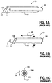
- FIG 1A illustrates an example of a prior art solid blunt 103 within the shaft 105 of the needle assembly 101.
- the needle 107 includes a hollow opening 109 and a sharp tip 107 at the end of the opening.
- the needle assembly 101 is shown in Figure 1A before its use.
- the solid rod blunt 103 is disposed entirely within the shaft of the needle 105 such that the sharp point 107 can pierce an object, such as the skin of a patient.
- the solid rod blunt 103 is advanced longitudinally along the longitudinal axis 120 shown in Figure 1B such that the end 111 of the solid blunt 103 extends beyond the opening of the shaft 105, thereby to some extent covering the sharp tip 107 so that a user of the needle may not receive an accidental needle stick.
- FIG. 1C shows a cross-sectional view of the assembly 101 shown in Figure 1B at the line 1C-1C shown in Figure 1B. As can be seen from Figure 1C, there is a considerable gap 109a between the inner diameter of the shaft 105 and the outer diameter of the solid blunt rod 103.
- the present invention provides a solid blunt which helps to prevent accidental needle sticks.
- the present invention also provides a needle assembly having a solid blunt.
- a solid blunt has an outer dimension (e.g. outer diameter) which is nearly equal to an inner dimension (e.g. inner diameter) of a cannula of a needle which is configured to contain the solid blunt.
- the solid blunt substantially blocks fluid flow along a first circumferential portion of an inner diameter of the cannula and allows fluid flow in a second circumferential portion of the inner diameter.
- the solid blunt is typically capable of longitudinal movement through the cannula and is prevented from moving substantially in a direction perpendicular to the longitudinal movement.
- a needle assembly in another exemplary embodiment, includes a solid blunt, a cannula, and a clip which couples the solid blunt to a frame which is coupled to the cannula.
- the clip allows the solid blunt to move longitudinally between at least two positions and the clip prevents the solid blunt from rotating within the shaft of the needle.
- the solid blunt itself is effectively lodged within the shaft of the needle so that it cannot move substantially in a direction perpendicular to the longitudinal movement of the solid blunt.
- the present invention may be used with medical devices, including needles, catheter assemblies and introducers for catheters and other devices as well.
- the present invention provides various examples of solid blunts and needle assemblies containing solid blunts.
- the following description and drawings are illustrative of the invention and are not to be construed as limiting the invention. Numerous specific details are described to provide a thorough understanding of the invention. For example, very specific geometries and dimensions are provided for purposes of illustrating the invention. In certain instances, well known or conventional details are not described in order to not unnecessarily obscure the present invention in detail.
- a solid blunt according to the present invention has an outer dimension, such as an outer diameter, which is nearly equal to (e.g. just less than) an inner dimension, such as an inner diameter, of a cannula of a needle which is configured to contain the solid blunt. At least a portion of the solid blunt having this outer dimension is configured to be positioned near a sharp tip of the needle when the blunt is positioned to protect against needle skiving, such as when the blunt is extended longitudinally out beyond the opening of the needle.
- the solid blunt is formed in a manner to provide a fluid flow through a fluid path of sufficient size while positioning the surface of the blunt (e.g. the outside diameter) as close to the sharp point of the needle (e.g. inside diameter) as possible.
- At least a portion of the solid blunt may substantially block fluid flow along a first circumferential portion of an inner diameter of the cannula while allowing fluid flow in a second circumferential portion of the inner diameter.
- a typical blunt according to the present invention may be capable of longitudinal movement through the cannula but be prevented from moving substantially in a direction which is perpendicular to the longitudinal movement. By being prevented from moving in this perpendicular direction, the outside dimension of the blunt will be positioned close to the sharp point of the needle and thereby reduce the likelihood that the sharp point will scratch or skive a person's skin.
- Figure 2A shows an example of a solid blunt 201 which has one particular geometry which resembles the letter "D" in the cross-sectional view of the solid blunt 201.
- This solid blunt 201 includes an outer circumferential portion or surface 203 and an upper flat portion 209.
- the solid interior 205 of the blunt extends from the circumferential portion 203 beyond the centerline 207 and up to the flat portion 209.
- the centerline 207 is designed to be the central diameter of a cannula which receives the solid blunt 201.
- Figure 3A shows an example of a needle assembly 301 which includes the solid blunt 201 and the shaft 303 of a needle.
- the solid blunt is disposed within the shaft of the needle 303 such that the bulk of the solid blunt is positioned near the needle's sharp tip 311 which is shown diagrammatically in the cross-sectional view of Figure 3A.
- the circumferential portion 203 of the outer surface of the solid blunt is closely positioned to the inner diameter 307 of the shaft 303.
- very little gap 309 exists between the blunt 201 and the shaft 303 along at least a first circumferential portion of the inner diameter of the shaft 303.
- fluid flow is allowed to occur through the opening 305 which exists above the solid blunt 201 as shown in Figure 3A.
- the blunt 201 includes material at or above the centerline 207 as shown in Figure 3A so that the blunt cannot move substantially in a perpendicular direction relative to the longitudinal movement of the blunt 201 within the shaft 303. That is, by having solid material of the blunt at or above the centerline of the shaft 303, the blunt resists movement in this perpendicular direction.
- Figure 2B shows another example of a particular geometry of a solid blunt according to the present invention.
- This particular geometry is referred to as a pie-slice shaped solid blunt due to the fact that the cross-section of the blunt as shown in Figure 2B resembles a pie slice.
- the blunt 211 of Figure 2B includes a first circumferential portion or outer surface 213 and a second circumferential portion or outer surface 215. Each of these circumferential portions are designed to come in close contact with the inner diameter of the shaft 303 as shown in Figure 3B.
- the outer diameter of the blunt is nearly equal to (but just less than) the inner diameter of shaft 303. Thus, only a very small gap exists between the portion 213 and the inner diameter 307 of the shaft 303 as shown in Figure 3B.
- FIG. 2B shows in its cross-sectional view a particular geometry in which the sides 217a and 217b are straight. It will be appreciated that alternatively the sides 217a and 217b may be either concave or convex.
- Figure 2C shows another specific geometry of a solid blunt according to the present invention.
- the solid blunt 221 shown in the cross-sectional view of Figure 2C includes a cut-out region 229. Even with the cut-out region, a solid portion 223 of the blunt 221 extends beyond the centerline 231 of the shaft 303 as shown in Figure 3C. Accordingly, the solid blunt 221 will resist perpendicular movement as described above.
- the outer circumferential portion 225 of the solid blunt 221 has a diameter which is nearly equal to (but just less than) the diameter of the shaft 303 and thus very little space or gap 309 exists between the outer surface of the solid blunt and the inner diameter 307 of the shaft 303.
- the blunt is positioned relative to the sharp tip 311 so that a majority of the solid blunt material will be disposed next to the sharp tip 311.
- Figure 2D shows another example of a particular geometry of a solid blunt according to the present invention
- the blunt 241 includes a D-shaped cut-out 249 in the upper surface 251 of the blunt.
- Sufficient solid material 245 of the blunt is at or above the centerline 247 of the shaft 303 as shown in Figure 3D.
- the outer circumferential portion 243 of the blunt 241 is sized relative to the inner diameter of the shaft 303 such that very little gap 309c exists between the inner diameter of the shaft 303 and the outer circumference of the blunt 241.
- the blunt 241 is positioned relative to the sharp tip 311 so that most of its solid material will be positioned near the tip 311.
- Figure 3E shows a side perspective view of the assembly 301 shown in Figure 3A.
- the cross-sectional view of Figure 3A is shown by line 3A-3A of Figure 3E.
- the needle assembly 301 as shown in Figure 3E, includes the solid blunt 201 which is disposed within the hollow inner diameter of the cannula formed by the shaft 303.
- the inner diameter 307 of the shaft 303 is nearly equal to (but just less than) the outer diameter of the blunt 201 such that the gap 309 is very small.
- the gap 305 between the top of the solid blunt 201 and the inner diameter 307 provides a sufficient fluid path through the shaft 303 when the needle is used.
- the close proximity between the outer circumferential portion 203 of the blunt 201 and its corresponding inner circumferential portion of the shaft 303 is such that fluid flow through the gap 309 is relatively restricted.
- the centerline 207 of the shaft 303 is shown relative to the solid blunt 201. It can be seen that a portion of the solid material of the solid blunt is at or above the centerline, thereby preventing the blunt from moving perpendicularly along the perpendicular direction 357 shown in Figure 3E .
- the blunt is capable of moving longitudinally along the longitudinal axis 353 under control of a conventional clip or other device (not shown) which is coupled to the blunt 201.
- This device such as a clip, may be attached directly to the blunt or through an intermediary piece which may have a different profile such as the rod 351 shown in Figure 3E.
- the rod 351 does not need to perform the functions of the solid blunt 201 and thus may have a different geometry than the solid blunt 201.
- the required geometry of the solid blunt 201 should exist around portions of the blunt that will be near the sharp tip 311.
- the clip or other device which controls and positions the solid blunt 201 may be similar to those devices in the prior art, such as those shown in U.S. Patents 5,009,642, or 5,540,662, or 4,828,547, or 5,743,882.
- the blunt 201 may be prevented from rotating (and thus stay positioned properly relative to the sharp tip 311) while also allowing for longitudinal movement along the axis 353 as shown in Figure 3E.
- the geometric configuration of the blunt according to the present invention will also prevent perpendicular movement along the axis 357 as shown in Figure 3E.
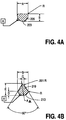
- Figures 4A and 4B show respectively particular examples of the D-shaped solid blunt and the pie-slice shaped solid blunt according to the present invention.
- Table A specifies examples for particular dimensions of the D-shaped blunt relative to certain specific needle shafts.
- Table B shows examples of specific dimensions for the pie-slice shaped blunt of Figure 4B.
- the tables show the nominal inner diameter (ID) of the needle and show the nominal outer diameter (OD) of the blunt. It can be seen that the OD of the blunt is less than but nearly equal to the ID of the needle. In a typical case, the OD of the blunt is 0.002 inches less than the ID of the blunt.
- Figures 4A and 4B represent the same labeled dimensions in the Tables A and B (for example, "A” in Figure 4A is a dimension shown in the column A ["Nominal Blunt OD"] of Table A).
- Figures 4A and 4B assume a cylindrical shape for the needle's shaft and the blunt so that a diameter may be used to describe the relative dimensions.
- a needle and a blunt each having triangular or elliptical cross-sections may be used where a dimension of the blunt nearly equals a dimension of the needle.
- FIGS 5A and 5B show an example of a catheter system 501 of the invention. It will be appreciated that the solid blunt of the present invention may be used with various different types of catheter systems and that Figures 5A and 5B show merely one example of such a system.
- the catheter system 501 includes a needle 502, a catheter hub 503, a solid D-shaped blunt 504, and a needle frame 507.
- the catheter hub 503 includes a tube 506 which surrounds the needle 502.
- the catheter hub 503 also includes a hub interconnect portion 503a which includes a section 503b disposed to engage a notch on the clip 511.
- Figure 5A shows the catheter system set before the needle is used so that the blunt is within the shaft of the needle.
- the solid blunt 504 is disposed within the shaft of the needle 502 and will extend beyond the opening of the needle 502 and beyond the sharp tip 505 of the needle 502 after the needle is used in accordance with conventional operating mechanisms for moving blunts.
- Figure 5B shows the catheter system after the needle is used.
- the needle frame 507 is coupled to a flash chamber 509 and is also coupled by means of a slidable joint to the end 515 of the blunt 504.
- the end 515 is coupled to the clip 511 so that when the catheter hub 503 is pulled away from the needle frame 507, the blunt 504 is pulled out (so that it extends out beyond the sharp tip 505) by the interaction between the hub at 503a and the clip at 511 and the lower portion of the needle frame 507.
- This lower portion of the needle frame 507 engages a portion of the clip 511 as shown in Figure 5B after the catheter hub 503 has been pulled away from the needle frame 507.
- This engagement between the lower portion of the needle frame 507 and the clip will keep the blunt extended out beyond the sharp tip 505 as shown in Figure 5B.
- Blood or other fluids which enter the opening of the needle 502 travel along the top of the solid blunt 504 along the line 513 towards the flash chamber 509. It will be appreciated that the solid blunts of the present invention may be used with various different needle assemblies having various different types of clips and other mechanisms for positioning the solid blunt and for allowing for longitudinal movement of the solid blunt relative to the shaft of the needle.
Landscapes
- Health & Medical Sciences (AREA)
- Life Sciences & Earth Sciences (AREA)
- Animal Behavior & Ethology (AREA)
- General Health & Medical Sciences (AREA)
- Biomedical Technology (AREA)
- Heart & Thoracic Surgery (AREA)
- Hematology (AREA)
- Engineering & Computer Science (AREA)
- Veterinary Medicine (AREA)
- Anesthesiology (AREA)
- Public Health (AREA)
- Vascular Medicine (AREA)
- Biophysics (AREA)
- Pulmonology (AREA)
- Infusion, Injection, And Reservoir Apparatuses (AREA)
- Portable Nailing Machines And Staplers (AREA)
- Finger-Pressure Massage (AREA)
- Impact Printers (AREA)
Abstract
Description
- The present invention relates to medical devices and other similar devices and in particular to medical devices such as intravenous catheters and syringes which include a hollow needle having a sharp distal end for piercing an object, such as the skin of a patient.
- The existence of infectious diseases has highlighted the danger to which medical personnel may be exposed when treating patients by means of catheter devices and syringes where a sharp needle point is used to pierce the skin of the patient In order to protect medical personnel against inadvertent needle stick, a number of solutions have been developed whereby a protective mechanism, incorporated within a catheter or syringe, prevents physical contact with the sharp needle point after use and hence protects against inadvertent needle stick. Many of the developed solutions are complicated. For example, some developments utilize the retraction of the needle within a housing once the needle has been used. Other developments utilize blunts which are contained within the cannula of the hollow needle.
- These blunts come in two principal forms: hollow blunts which are hollow tubes concentrically disposed within the circular shaft of a hollow needle, and solid blunts. Hollow blunt designs require that an exit hole be provided at a proximal location to allow blood to exit the blunt and enter a flash chamber, the use of which is well known in the art. In order for blood flashback to be seen as quickly as possible, the exit hole needs to be located just proximal to the butt end of the needle. Thus, hollow blunts require extra machining or manufacturing steps in order to produce a satisfactory hollow blunt. Solid rod blunts are typically cylindrical rods which have an outer diameter which is sufficiently smaller than the inner diameter of the shaft of the cannula of the needle in order to allow clearance for fluid flow all around the diameter of the solid rod blunt. While some prior art designs have included grooves in the solid rod blunt, these solid rod blunts nevertheless position the wall of the blunt (the outside diameter of the blunt) some distance from the inner diameter of the shaft of the cannula.
- Figure 1A illustrates an example of a prior art
solid blunt 103 within theshaft 105 of theneedle assembly 101. Theneedle 107 includes ahollow opening 109 and asharp tip 107 at the end of the opening. Theneedle assembly 101 is shown in Figure 1A before its use. In this situation, thesolid rod blunt 103 is disposed entirely within the shaft of theneedle 105 such that thesharp point 107 can pierce an object, such as the skin of a patient. After use, thesolid rod blunt 103 is advanced longitudinally along thelongitudinal axis 120 shown in Figure 1B such that theend 111 of thesolid blunt 103 extends beyond the opening of theshaft 105, thereby to some extent covering thesharp tip 107 so that a user of the needle may not receive an accidental needle stick. As is well known in the art, a clip or other mechanism holds thesolid blunt rod 103 relative to theshaft 105, preventing it from moving longitudinally along theaxis 120 once theblunt 103 has been extended beyond the opening. However, as shown in Figure 1C, it is also possible for thesolid blunt 103 to move perpendicularly to thelongitudinal axis 120 and this tends to increase the gap between the blunt and the sharp tip which tends to increase the likelihood of an accidental needle stick or skive. Figure 1C shows a cross-sectional view of theassembly 101 shown in Figure 1B at theline 1C-1C shown in Figure 1B. As can be seen from Figure 1C, there is a considerable gap 109a between the inner diameter of theshaft 105 and the outer diameter of thesolid blunt rod 103. This makes it possible for the rod to move up and down along theaxis 130 which is perpendicular to thelongitudinal axis 120 shown in Figure 1B. As a result, it is possible for theblunt 103 to be pushed away from thesharp tip 107 even when it is extended out beyond thetip 107 as shown in Figure 1B. As a result, even though the blunt may be advanced longitudinally beyond the end of the sharp tip of the needle, the gap between the wall of the blunt and the sharp tip may be so large that the sharp point is permitted to scratch or skive a person's skin. Naturally, the solid blunt must provide space around its circumference in order to permit fluid flow, and thus it would appear that a gap 109a is required. - From the above discussion, it can be seen that it is desirable to provide an improved solid blunt which better protects a user of a needle.
- The present invention provides a solid blunt which helps to prevent accidental needle sticks. The present invention also provides a needle assembly having a solid blunt.
- In one exemplary embodiment, a solid blunt has an outer dimension (e.g. outer diameter) which is nearly equal to an inner dimension (e.g. inner diameter) of a cannula of a needle which is configured to contain the solid blunt.
- In one example, the solid blunt substantially blocks fluid flow along a first circumferential portion of an inner diameter of the cannula and allows fluid flow in a second circumferential portion of the inner diameter. The solid blunt is typically capable of longitudinal movement through the cannula and is prevented from moving substantially in a direction perpendicular to the longitudinal movement.
- A needle assembly, in another exemplary embodiment, includes a solid blunt, a cannula, and a clip which couples the solid blunt to a frame which is coupled to the cannula. The clip allows the solid blunt to move longitudinally between at least two positions and the clip prevents the solid blunt from rotating within the shaft of the needle. The solid blunt itself is effectively lodged within the shaft of the needle so that it cannot move substantially in a direction perpendicular to the longitudinal movement of the solid blunt.
- The present invention may be used with medical devices, including needles, catheter assemblies and introducers for catheters and other devices as well.
- The present invention is illustrated by way of example and not limitation in the figures of the accompanying drawings in which like references indicate similar elements.
- Figure 1A shows a cross-sectional view of a prior art blunt within a needle shaft. This view depicts the typical position of the blunt relative to the shaft and tip of the needle before use of the needle.
- Figure 1B shows a cross-sectional view of a prior an needle assembly having a blunt which is extended beyond the tip of the needle after use of the needle.
- Figure 1C shows a cross-sectional view of a solid blunt within a needle
shaft; this cross-sectional view is taken along the
line 1C-1C shown in Figure 1B. - Figures 2A, 2B, 2C, and 2D show cross-sectional views of four examples of solid blunts according to the present invention.
- Figures 3A, 3B, 3C, and 3D show cross-sectional views of the blunts
shown respectively in Figures 2A, 2B, 2C, and 2D within the shaft of a needle.
Figures 3A, 3B, 3C, and 3D also illustrate the relative position of portions of the
blunt and the
sharp tip 311 of the needle and blunt assembly. - Figure 3E shows the perspective side view of a needle and blunt assembly according to the present invention.
- Figure 4A shows another cross-sectional view of an example of a specific solid blunt according to the present invention.
- Figure 4B shows another example of a specific solid blunt according to the present invention.
- Figures 5A and 5B show cross-sectional views of an example of a catheter assembly which may use a solid blunt according to the present invention.
-
- The present invention provides various examples of solid blunts and needle assemblies containing solid blunts. The following description and drawings are illustrative of the invention and are not to be construed as limiting the invention. Numerous specific details are described to provide a thorough understanding of the invention. For example, very specific geometries and dimensions are provided for purposes of illustrating the invention. In certain instances, well known or conventional details are not described in order to not unnecessarily obscure the present invention in detail.
- Generally, a solid blunt according to the present invention has an outer dimension, such as an outer diameter, which is nearly equal to (e.g. just less than) an inner dimension, such as an inner diameter, of a cannula of a needle which is configured to contain the solid blunt. At least a portion of the solid blunt having this outer dimension is configured to be positioned near a sharp tip of the needle when the blunt is positioned to protect against needle skiving, such as when the blunt is extended longitudinally out beyond the opening of the needle. The solid blunt is formed in a manner to provide a fluid flow through a fluid path of sufficient size while positioning the surface of the blunt (e.g. the outside diameter) as close to the sharp point of the needle (e.g. inside diameter) as possible. Thus, at least a portion of the solid blunt may substantially block fluid flow along a first circumferential portion of an inner diameter of the cannula while allowing fluid flow in a second circumferential portion of the inner diameter. A typical blunt according to the present invention may be capable of longitudinal movement through the cannula but be prevented from moving substantially in a direction which is perpendicular to the longitudinal movement. By being prevented from moving in this perpendicular direction, the outside dimension of the blunt will be positioned close to the sharp point of the needle and thereby reduce the likelihood that the sharp point will scratch or skive a person's skin.
- Figure 2A shows an example of a
solid blunt 201 which has one particular geometry which resembles the letter "D" in the cross-sectional view of thesolid blunt 201. Thissolid blunt 201 includes an outer circumferential portion orsurface 203 and an upperflat portion 209. Thesolid interior 205 of the blunt extends from thecircumferential portion 203 beyond thecenterline 207 and up to theflat portion 209. Thecenterline 207 is designed to be the central diameter of a cannula which receives the solid blunt 201. - Figure 3A shows an example of a
needle assembly 301 which includes the solid blunt 201 and theshaft 303 of a needle. The solid blunt is disposed within the shaft of theneedle 303 such that the bulk of the solid blunt is positioned near the needle'ssharp tip 311 which is shown diagrammatically in the cross-sectional view of Figure 3A. As can be seen from Figure 3A, thecircumferential portion 203 of the outer surface of the solid blunt is closely positioned to theinner diameter 307 of theshaft 303. Thus verylittle gap 309 exists between the blunt 201 and theshaft 303 along at least a first circumferential portion of the inner diameter of theshaft 303. However, fluid flow is allowed to occur through theopening 305 which exists above the solid blunt 201 as shown in Figure 3A. The blunt 201 includes material at or above thecenterline 207 as shown in Figure 3A so that the blunt cannot move substantially in a perpendicular direction relative to the longitudinal movement of the blunt 201 within theshaft 303. That is, by having solid material of the blunt at or above the centerline of theshaft 303, the blunt resists movement in this perpendicular direction. - Figure 2B shows another example of a particular geometry of a solid blunt according to the present invention. This particular geometry is referred to as a pie-slice shaped solid blunt due to the fact that the cross-section of the blunt as shown in Figure 2B resembles a pie slice. The blunt 211 of Figure 2B includes a first circumferential portion or
outer surface 213 and a second circumferential portion orouter surface 215. Each of these circumferential portions are designed to come in close contact with the inner diameter of theshaft 303 as shown in Figure 3B. In one case, the outer diameter of the blunt is nearly equal to (but just less than) the inner diameter ofshaft 303. Thus, only a very small gap exists between theportion 213 and theinner diameter 307 of theshaft 303 as shown in Figure 3B. Thesolid interior 219 of the blunt 211 extends from one circumferential portion to the other circumferential portion, thereby resisting perpendicular movement of the blunt. Figure 2B shows in its cross-sectional view a particular geometry in which the sides 217a and 217b are straight. It will be appreciated that alternatively the sides 217a and 217b may be either concave or convex. - Figure 2C shows another specific geometry of a solid blunt according to the present invention. The solid blunt 221 shown in the cross-sectional view of Figure 2C includes a cut-out
region 229. Even with the cut-out region, asolid portion 223 of the blunt 221 extends beyond thecenterline 231 of theshaft 303 as shown in Figure 3C. Accordingly, the solid blunt 221 will resist perpendicular movement as described above. The outercircumferential portion 225 of the solid blunt 221 has a diameter which is nearly equal to (but just less than) the diameter of theshaft 303 and thus very little space orgap 309 exists between the outer surface of the solid blunt and theinner diameter 307 of theshaft 303. Also as shown in Figure 3C, the blunt is positioned relative to thesharp tip 311 so that a majority of the solid blunt material will be disposed next to thesharp tip 311. - Figure 2D shows another example of a particular geometry of a solid blunt according to the present invention, in the cross-sectional view of Figure 2D, the blunt 241 includes a D-shaped cut-out 249 in the
upper surface 251 of the blunt. Sufficientsolid material 245 of the blunt is at or above thecenterline 247 of theshaft 303 as shown in Figure 3D. The outercircumferential portion 243 of the blunt 241 is sized relative to the inner diameter of theshaft 303 such that very little gap 309c exists between the inner diameter of theshaft 303 and the outer circumference of the blunt 241. The blunt 241 is positioned relative to thesharp tip 311 so that most of its solid material will be positioned near thetip 311. - Figure 3E shows a side perspective view of the
assembly 301 shown in Figure 3A. The cross-sectional view of Figure 3A is shown byline 3A-3A of Figure 3E. Theneedle assembly 301, as shown in Figure 3E, includes the solid blunt 201 which is disposed within the hollow inner diameter of the cannula formed by theshaft 303. Theinner diameter 307 of theshaft 303 is nearly equal to (but just less than) the outer diameter of the blunt 201 such that thegap 309 is very small. Thegap 305 between the top of the solid blunt 201 and theinner diameter 307 provides a sufficient fluid path through theshaft 303 when the needle is used. On the other hand, the close proximity between the outercircumferential portion 203 of the blunt 201 and its corresponding inner circumferential portion of theshaft 303 is such that fluid flow through thegap 309 is relatively restricted. Thecenterline 207 of theshaft 303 is shown relative to the solid blunt 201. It can be seen that a portion of the solid material of the solid blunt is at or above the centerline, thereby preventing the blunt from moving perpendicularly along theperpendicular direction 357 shown in Figure 3E. The blunt is capable of moving longitudinally along thelongitudinal axis 353 under control of a conventional clip or other device (not shown) which is coupled to the blunt 201. This device, such as a clip, may be attached directly to the blunt or through an intermediary piece which may have a different profile such as therod 351 shown in Figure 3E. Therod 351 does not need to perform the functions of the solid blunt 201 and thus may have a different geometry than the solid blunt 201. The required geometry of the solid blunt 201 should exist around portions of the blunt that will be near thesharp tip 311. The clip or other device which controls and positions the solid blunt 201 may be similar to those devices in the prior art, such as those shown in U.S. Patents 5,009,642, or 5,540,662, or 4,828,547, or 5,743,882. These clips or devices, using conventional mechanisms, allow for the blunt to move longitudinally but prevent the blunt from moving circularly (e.g. rotating) within theshaft 303; this circular direction is shown by thearrow 355 shown in Figure 3E. Thus by using a conventional clip or other device for retaining and controlling the movement longitudinally of the blunt 201, the blunt 201 may be prevented from rotating (and thus stay positioned properly relative to the sharp tip 311) while also allowing for longitudinal movement along theaxis 353 as shown in Figure 3E. The geometric configuration of the blunt according to the present invention will also prevent perpendicular movement along theaxis 357 as shown in Figure 3E. - Figures 4A and 4B show respectively particular examples of the D-shaped solid blunt and the pie-slice shaped solid blunt according to the present invention. These particular figures and the following tables provide various specific examples for dimensions which are specified in the following tables. In particular, Table A below specifies examples for particular dimensions of the D-shaped blunt relative to certain specific needle shafts. Similarly, Table B shows examples of specific dimensions for the pie-slice shaped blunt of Figure 4B. The tables show the nominal inner diameter (ID) of the needle and show the nominal outer diameter (OD) of the blunt. It can be seen that the OD of the blunt is less than but nearly equal to the ID of the needle. In a typical case, the OD of the blunt is 0.002 inches less than the ID of the blunt. The labels on the Figures 4A and 4B represent the same labeled dimensions in the Tables A and B (for example, "A" in Figure 4A is a dimension shown in the column A ["Nominal Blunt OD"] of Table A). These examples of Figures 4A and 4B assume a cylindrical shape for the needle's shaft and the blunt so that a diameter may be used to describe the relative dimensions. It will be appreciated that other geometries for the needle and blunt may be used with the present invention; for example, a needle and a blunt each having triangular or elliptical cross-sections may be used where a dimension of the blunt nearly equals a dimension of the needle.
Nominal Needle ID Nominal Blunt OD A B flat Location 0.050 .0475 .029 0.038 .036 .021 0.030 .028 .018 0.023 .021 .012 0.017 .015 .009 0.014 .012 .007 Nominal Needle ID Nominal Blunt OD A B Base C D (Ref) E (Ref) 0.050 .0475 0.0450 0.0122 0.0172 0.0573 0.038 .036 0.0319 0.0048 0.0110 0.0400 0.030 .028 0.0237 0.0024 0.0082 0.0300 0.023 .021 0.0181 0.0018 0.0060 0.0225 0.017 .015 0.0132 0.0018 0.0045 0.0165 0.014 .012 0.0103 0.0012 0.0035 0.0130 - Figures 5A and 5B show an example of a
catheter system 501 of the invention. It will be appreciated that the solid blunt of the present invention may be used with various different types of catheter systems and that Figures 5A and 5B show merely one example of such a system. Thecatheter system 501 includes aneedle 502, acatheter hub 503, a solid D-shaped blunt 504, and aneedle frame 507. Thecatheter hub 503 includes atube 506 which surrounds theneedle 502. Thecatheter hub 503 also includes a hub interconnect portion 503a which includes a section 503b disposed to engage a notch on theclip 511. Figure 5A shows the catheter system set before the needle is used so that the blunt is within the shaft of the needle. The solid blunt 504 is disposed within the shaft of theneedle 502 and will extend beyond the opening of theneedle 502 and beyond thesharp tip 505 of theneedle 502 after the needle is used in accordance with conventional operating mechanisms for moving blunts. Figure 5B shows the catheter system after the needle is used. Theneedle frame 507 is coupled to aflash chamber 509 and is also coupled by means of a slidable joint to theend 515 of the blunt 504. Theend 515 is coupled to theclip 511 so that when thecatheter hub 503 is pulled away from theneedle frame 507, the blunt 504 is pulled out (so that it extends out beyond the sharp tip 505) by the interaction between the hub at 503a and the clip at 511 and the lower portion of theneedle frame 507. This lower portion of theneedle frame 507 engages a portion of theclip 511 as shown in Figure 5B after thecatheter hub 503 has been pulled away from theneedle frame 507. This engagement between the lower portion of theneedle frame 507 and the clip will keep the blunt extended out beyond thesharp tip 505 as shown in Figure 5B. Blood or other fluids which enter the opening of theneedle 502 travel along the top of the solid blunt 504 along theline 513 towards theflash chamber 509. It will be appreciated that the solid blunts of the present invention may be used with various different needle assemblies having various different types of clips and other mechanisms for positioning the solid blunt and for allowing for longitudinal movement of the solid blunt relative to the shaft of the needle. - In the foregoing specification, the invention has been described with reference to specific exemplary embodiments thereof. It will be evident that various modifications may be made thereto without departing from the broader spirit and scope of the invention as set forth in the following claims. The specification and drawings are, accordingly, to be regarded in an illustrative sense rather than a restrictive sense.
Claims (14)
- A solid blunt having an outer dimension which is nearly equal to an inner dimension of a cannula of a needle which is configured to contain said solid blunt.
- A solid blunt as in claim 1 wherein said outer dimension is an outer diameter and wherein a portion of said solid blunt having said outer dimension is configured to be positioned near a sharp tip of said needle.
- A solid blunt as in claim 1 wherein said solid blunt has one of: (a) a substantially D-shaped cross-section; (b) a substantially pie-slice shaped cross-section; or (c) a circular cross-section having a cut-out region.
- A solid blunt as in claim 3 wherein said cut-out region resembles one of a "U" or a "V" shape.
- A solid blunt as in claim 4 wherein said solid blunt has one of (a) a substantially D-shaped cross-section or (b) a substantially pie-slice shaped cross-section and wherein a portion of said solid blunt extends from substantially near said first circumferential portion to at least a centerline of said cannula.
- A needle assembly comprising:a cannula having an inner wall which defines an inner dimension and a sharp tip;a solid blunt disposed within said cannula, said solid blunt having an outer dimension which is nearly equal to said inner dimension of said cannula.
- A needle assembly as in claim 6 wherein said solid blunt is as defined in any one of claims 1 to 5.
- A needle assembly as in claim 6 or claim 7 wherein: said cannula has a substantially circular cross-section; said inner dimension is an inner diameter; said outer dimension is an outer diameter; said solid blunt has a portion of a substantially circular cross-section; and a portion of said solid blunt having said outer dimension is configured to be positioned near said sharp tip.
- A needle assembly as in any one of claims 6 to 8 further comprising:a clip coupled to said solid blunt, said clip being coupled slidably to a frame which is coupled to said cannula so that said solid blunt cannot rotate within said cannula, and wherein said solid blunt is held in one of two positions by said clip: (a) a first position in which said solid blunt does not extend beyond said sharp tip and is within said cannula, and (b) a second position in which said solid blunt extends beyond said sharp tip and outside of said cannula.
- A needle assembly as in claim 8 wherein: said solid blunt substantially blocks fluid flow in a first circumferential portion of said inner diameter of said cannula and allows fluid flow in a second circumferential portion of said inner diameter; and said solid blunt is capable of longitudinal movement through said cannula and is prevented from moving substantially in a direction perpendicular to said longitudinal movement.
- A needle assembly as in claim 10 wherein said longitudinal movement comprises movement between (a) a first position to which said solid blunt does not extend beyond said sharp tip and is within said cannula, an (b) a second position in which said solid blunt extends beyond said sharp tip and outside of said cannula.
- A needle assembly as in claim 11 wherein said solid blunt is prevented from rotating in said cannula.
- A needle assembly as in claim 11 wherein a portion of said solid blunt extends from substantially near said first circumferential portion to at least a centerline of said cannula.
- A needle assembly as in claim 13 wherein said solid blunt extends at least one-half of said inner diameter.
Applications Claiming Priority (2)
| Application Number | Priority Date | Filing Date | Title |
|---|---|---|---|
| US09/221,272 US6391007B2 (en) | 1998-12-23 | 1998-12-23 | Solid blunt for a needle assembly |
| US221272 | 1998-12-23 |
Publications (3)
| Publication Number | Publication Date |
|---|---|
| EP1013300A2 true EP1013300A2 (en) | 2000-06-28 |
| EP1013300A3 EP1013300A3 (en) | 2002-06-19 |
| EP1013300B1 EP1013300B1 (en) | 2004-05-26 |
Family
ID=22827106
Family Applications (1)
| Application Number | Title | Priority Date | Filing Date |
|---|---|---|---|
| EP99310423A Expired - Lifetime EP1013300B1 (en) | 1998-12-23 | 1999-12-22 | Blunt stylet for needle assembly |
Country Status (15)
| Country | Link |
|---|---|
| US (2) | US6391007B2 (en) |
| EP (1) | EP1013300B1 (en) |
| JP (1) | JP4166915B2 (en) |
| KR (1) | KR20000057077A (en) |
| CN (1) | CN1210075C (en) |
| AT (1) | ATE267622T1 (en) |
| AU (1) | AU768218B2 (en) |
| BR (1) | BR9905960A (en) |
| CA (1) | CA2293001C (en) |
| CO (1) | CO5210908A1 (en) |
| DE (1) | DE69917573T2 (en) |
| ES (1) | ES2222017T3 (en) |
| SG (1) | SG90714A1 (en) |
| TW (1) | TW445155B (en) |
| ZA (1) | ZA997828B (en) |
Families Citing this family (15)
| Publication number | Priority date | Publication date | Assignee | Title |
|---|---|---|---|---|
| EP1011757B1 (en) * | 1997-03-26 | 2005-01-12 | Bio-Plexus, Inc. | Parenteral fluid transfer apparatus |
| US6544239B2 (en) | 1998-10-16 | 2003-04-08 | Bio-Plexus Delaware, Inc. | Releasable locking needle assembly with optional release accessory therefor |
| US6391007B2 (en) * | 1998-12-23 | 2002-05-21 | Joseph Jawshin Chang | Solid blunt for a needle assembly |
| DE10008825C2 (en) * | 2000-02-25 | 2002-11-21 | Disetronic Licensing Ag | micro perfusion |
| US6837878B2 (en) * | 2001-01-09 | 2005-01-04 | Icu Medical, Inc. | Bluntable needle assembly with open-ended blunting probe |
| US20050096594A1 (en) * | 2002-04-30 | 2005-05-05 | Doctor's Research Group, Incorporated | Cannula arrangements |
| US20030208160A1 (en) * | 2002-05-02 | 2003-11-06 | Becton, Dickinson And Company | Needle assembly |
| US7651482B2 (en) * | 2005-02-04 | 2010-01-26 | Boston Scientific Scimed, Inc. | Non-coring needles and methods of manufacturing same |
| US8021338B2 (en) * | 2005-09-14 | 2011-09-20 | Boston Scientific Scimed, Inc. | Percutaneous endoscopic jejunostomy access needle |
| US7959595B2 (en) | 2007-09-18 | 2011-06-14 | Cook Medical Technologies Llc | Catheter assembly |
| US9283331B2 (en) | 2010-11-30 | 2016-03-15 | University Of Utah Research Foundation | Hypodermic needle system and method of use to reduce infection |
| US20160287797A1 (en) * | 2015-04-02 | 2016-10-06 | XEND Medical, LLC | Hypodermic needle system having a spacer |
| US20160361088A1 (en) * | 2015-06-12 | 2016-12-15 | Covidien Lp | Catheter with pre-formed geometry for body lumen access |
| EP3337531A1 (en) | 2015-08-20 | 2018-06-27 | Persons, Barbara | Integrated needle and cannula for plastic surgery |
| WO2020172080A1 (en) * | 2019-02-21 | 2020-08-27 | Boubes Khaled | Locking hemodialysis needle assembly with integral needle tip protector |
Citations (4)
| Publication number | Priority date | Publication date | Assignee | Title |
|---|---|---|---|---|
| US4828547A (en) | 1987-09-28 | 1989-05-09 | Bio-Plexus, Inc. | Self-blunting needle assembly and device including the same |
| US5009642A (en) | 1987-09-28 | 1991-04-23 | Bio-Plexus, Inc. | Self-blunting needle assembly for use with a catheter, and catheter assembly using the same |
| US5540662A (en) | 1993-12-10 | 1996-07-30 | The Boc Group Plc | Medical devices |
| US5743882A (en) | 1996-03-08 | 1998-04-28 | Luther Medical Products, Inc. | Needle blunting assembly for use with intravascular introducers |
Family Cites Families (13)
| Publication number | Priority date | Publication date | Assignee | Title |
|---|---|---|---|---|
| US4010737A (en) * | 1971-06-14 | 1977-03-08 | Vilaghy Miklos I | Bone biopsy instrument kit |
| US3788320A (en) * | 1972-02-25 | 1974-01-29 | Kendall & Co | Spinal needle |
| US4619643A (en) * | 1983-07-25 | 1986-10-28 | Bai Chao Liang | Catheter |
| US4610671A (en) * | 1985-03-28 | 1986-09-09 | Luther Medical Products, Inc. | Assembly of stylet and catheter |
| US5201712A (en) * | 1991-09-19 | 1993-04-13 | Abbott Laboratories | Catheter assembly with reciprocable obturator |
| US5312345A (en) * | 1992-03-11 | 1994-05-17 | Cole Richard D | Anti-needle stick protective inner blunt tubular stylet for intravenous therapy |
| US5472430A (en) * | 1993-08-18 | 1995-12-05 | Vlv Associates | Protected needle assembly |
| US5490521A (en) * | 1993-08-31 | 1996-02-13 | Medtronic, Inc. | Ultrasound biopsy needle |
| AUPN941296A0 (en) * | 1996-04-22 | 1996-05-16 | Pisaniello, Luigi Luke | A safety hypodermic needle |
| EP1011757B1 (en) * | 1997-03-26 | 2005-01-12 | Bio-Plexus, Inc. | Parenteral fluid transfer apparatus |
| US6056718A (en) | 1998-03-04 | 2000-05-02 | Minimed Inc. | Medication infusion set |
| US6544239B2 (en) | 1998-10-16 | 2003-04-08 | Bio-Plexus Delaware, Inc. | Releasable locking needle assembly with optional release accessory therefor |
| US6391007B2 (en) * | 1998-12-23 | 2002-05-21 | Joseph Jawshin Chang | Solid blunt for a needle assembly |
-
1998
- 1998-12-23 US US09/221,272 patent/US6391007B2/en not_active Expired - Lifetime
-
1999
- 1999-12-01 SG SG9906080A patent/SG90714A1/en unknown
- 1999-12-21 AU AU65377/99A patent/AU768218B2/en not_active Expired
- 1999-12-21 KR KR1019990059590A patent/KR20000057077A/en active IP Right Grant
- 1999-12-21 CA CA002293001A patent/CA2293001C/en not_active Expired - Lifetime
- 1999-12-22 BR BR9905960-6A patent/BR9905960A/en not_active IP Right Cessation
- 1999-12-22 DE DE69917573T patent/DE69917573T2/en not_active Expired - Lifetime
- 1999-12-22 EP EP99310423A patent/EP1013300B1/en not_active Expired - Lifetime
- 1999-12-22 ES ES99310423T patent/ES2222017T3/en not_active Expired - Lifetime
- 1999-12-22 ZA ZA9907828A patent/ZA997828B/en unknown
- 1999-12-22 CO CO99080092A patent/CO5210908A1/en not_active Application Discontinuation
- 1999-12-22 JP JP36540199A patent/JP4166915B2/en not_active Expired - Fee Related
- 1999-12-22 AT AT99310423T patent/ATE267622T1/en not_active IP Right Cessation
- 1999-12-23 CN CNB991274156A patent/CN1210075C/en not_active Expired - Fee Related
-
2000
- 2000-01-21 TW TW088122692A patent/TW445155B/en not_active IP Right Cessation
-
2002
- 2002-03-13 US US10/098,646 patent/US6676636B2/en not_active Expired - Lifetime
Patent Citations (4)
| Publication number | Priority date | Publication date | Assignee | Title |
|---|---|---|---|---|
| US4828547A (en) | 1987-09-28 | 1989-05-09 | Bio-Plexus, Inc. | Self-blunting needle assembly and device including the same |
| US5009642A (en) | 1987-09-28 | 1991-04-23 | Bio-Plexus, Inc. | Self-blunting needle assembly for use with a catheter, and catheter assembly using the same |
| US5540662A (en) | 1993-12-10 | 1996-07-30 | The Boc Group Plc | Medical devices |
| US5743882A (en) | 1996-03-08 | 1998-04-28 | Luther Medical Products, Inc. | Needle blunting assembly for use with intravascular introducers |
Also Published As
| Publication number | Publication date |
|---|---|
| AU768218B2 (en) | 2003-12-04 |
| CO5210908A1 (en) | 2002-10-30 |
| US6676636B2 (en) | 2004-01-13 |
| ES2222017T3 (en) | 2005-01-16 |
| DE69917573D1 (en) | 2004-07-01 |
| SG90714A1 (en) | 2002-08-20 |
| US20020147428A1 (en) | 2002-10-10 |
| US20010025158A1 (en) | 2001-09-27 |
| ZA997828B (en) | 2001-06-22 |
| BR9905960A (en) | 2001-01-16 |
| EP1013300B1 (en) | 2004-05-26 |
| CN1210075C (en) | 2005-07-13 |
| CA2293001A1 (en) | 2000-06-23 |
| CN1260212A (en) | 2000-07-19 |
| ATE267622T1 (en) | 2004-06-15 |
| US6391007B2 (en) | 2002-05-21 |
| DE69917573T2 (en) | 2005-07-21 |
| JP4166915B2 (en) | 2008-10-15 |
| EP1013300A3 (en) | 2002-06-19 |
| JP2000245838A (en) | 2000-09-12 |
| KR20000057077A (en) | 2000-09-15 |
| CA2293001C (en) | 2007-12-04 |
| AU6537799A (en) | 2000-06-29 |
| TW445155B (en) | 2001-07-11 |
Similar Documents
| Publication | Publication Date | Title |
|---|---|---|
| EP1013300B1 (en) | Blunt stylet for needle assembly | |
| JP4981030B2 (en) | Protection device to protect the injection needle | |
| KR100401080B1 (en) | Intravenous catheter with self-positioning needle protection | |
| US5549558A (en) | Self sheathing safety needle | |
| US7303548B2 (en) | Catheter introducer assembly having safety shielded needle | |
| EP1861134B1 (en) | Method of making a needle shielding device | |
| US4846805A (en) | Catheter insert device | |
| EP2168621B1 (en) | Safety Shield for Medical Needles | |
| US5738660A (en) | Percutaneous port catheter assembly and method of use | |
| US9533108B2 (en) | Safety shield for medical needles | |
| US10406296B2 (en) | Telescoping safety shield for needles | |
| BRPI1011475B1 (en) | CANNON RESOURCE CAPTURE MECHANISM, BLOOD CONTAINER AND METHOD TO PROVIDE A SET FOR A CANNEL TIP PROTECTION DEVICE | |
| US5817060A (en) | Unidirectional blunting apparatus for hypodermic needles | |
| US20140309618A1 (en) | Safety Device Actuation System | |
| EP3965862A1 (en) | Catheter needle assembly with enclosable needle | |
| US5512050A (en) | Needle assembly with collapsible and retractable sheath | |
| CA2599501C (en) | Solid blunt for a needle assembly | |
| MXPA99011705A (en) | Solid bar with punta roma for an ag assembly |
Legal Events
| Date | Code | Title | Description |
|---|---|---|---|
| PUAI | Public reference made under article 153(3) epc to a published international application that has entered the european phase |
Free format text: ORIGINAL CODE: 0009012 |
|
| AK | Designated contracting states |
Kind code of ref document: A2 Designated state(s): AT BE CH CY DE DK ES FI FR GB GR IE IT LI LU MC NL PT SE |
|
| AX | Request for extension of the european patent |
Free format text: AL;LT;LV;MK;RO;SI |
|
| PUAL | Search report despatched |
Free format text: ORIGINAL CODE: 0009013 |
|
| AK | Designated contracting states |
Kind code of ref document: A3 Designated state(s): AT BE CH CY DE DK ES FI FR GB GR IE IT LI LU MC NL PT SE |
|
| AX | Request for extension of the european patent |
Free format text: AL;LT;LV;MK;RO;SI |
|
| 17P | Request for examination filed |
Effective date: 20021125 |
|
| AKX | Designation fees paid |
Designated state(s): AT BE CH CY DE DK ES FI FR GB GR IE IT LI LU MC NL PT SE |
|
| 17Q | First examination report despatched |
Effective date: 20030228 |
|
| GRAP | Despatch of communication of intention to grant a patent |
Free format text: ORIGINAL CODE: EPIDOSNIGR1 |
|
| GRAS | Grant fee paid |
Free format text: ORIGINAL CODE: EPIDOSNIGR3 |
|
| GRAA | (expected) grant |
Free format text: ORIGINAL CODE: 0009210 |
|
| AK | Designated contracting states |
Kind code of ref document: B1 Designated state(s): AT BE CH CY DE DK ES FI FR GB GR IE IT LI LU MC NL PT SE |
|
| PG25 | Lapsed in a contracting state [announced via postgrant information from national office to epo] |
Ref country code: LI Free format text: LAPSE BECAUSE OF FAILURE TO SUBMIT A TRANSLATION OF THE DESCRIPTION OR TO PAY THE FEE WITHIN THE PRESCRIBED TIME-LIMIT Effective date: 20040526 Ref country code: FI Free format text: LAPSE BECAUSE OF FAILURE TO SUBMIT A TRANSLATION OF THE DESCRIPTION OR TO PAY THE FEE WITHIN THE PRESCRIBED TIME-LIMIT Effective date: 20040526 Ref country code: CY Free format text: LAPSE BECAUSE OF FAILURE TO SUBMIT A TRANSLATION OF THE DESCRIPTION OR TO PAY THE FEE WITHIN THE PRESCRIBED TIME-LIMIT Effective date: 20040526 Ref country code: CH Free format text: LAPSE BECAUSE OF FAILURE TO SUBMIT A TRANSLATION OF THE DESCRIPTION OR TO PAY THE FEE WITHIN THE PRESCRIBED TIME-LIMIT Effective date: 20040526 Ref country code: BE Free format text: LAPSE BECAUSE OF FAILURE TO SUBMIT A TRANSLATION OF THE DESCRIPTION OR TO PAY THE FEE WITHIN THE PRESCRIBED TIME-LIMIT Effective date: 20040526 Ref country code: AT Free format text: LAPSE BECAUSE OF FAILURE TO SUBMIT A TRANSLATION OF THE DESCRIPTION OR TO PAY THE FEE WITHIN THE PRESCRIBED TIME-LIMIT Effective date: 20040526 |
|
| REG | Reference to a national code |
Ref country code: GB Ref legal event code: FG4D |
|
| REG | Reference to a national code |
Ref country code: CH Ref legal event code: EP |
|
| REG | Reference to a national code |
Ref country code: IE Ref legal event code: FG4D |
|
| REF | Corresponds to: |
Ref document number: 69917573 Country of ref document: DE Date of ref document: 20040701 Kind code of ref document: P |
|
| PG25 | Lapsed in a contracting state [announced via postgrant information from national office to epo] |
Ref country code: GR Free format text: LAPSE BECAUSE OF FAILURE TO SUBMIT A TRANSLATION OF THE DESCRIPTION OR TO PAY THE FEE WITHIN THE PRESCRIBED TIME-LIMIT Effective date: 20040826 Ref country code: DK Free format text: LAPSE BECAUSE OF FAILURE TO SUBMIT A TRANSLATION OF THE DESCRIPTION OR TO PAY THE FEE WITHIN THE PRESCRIBED TIME-LIMIT Effective date: 20040826 |
|
| REG | Reference to a national code |
Ref country code: SE Ref legal event code: TRGR |
|
| REG | Reference to a national code |
Ref country code: CH Ref legal event code: PL |
|
| PG25 | Lapsed in a contracting state [announced via postgrant information from national office to epo] |
Ref country code: LU Free format text: LAPSE BECAUSE OF NON-PAYMENT OF DUE FEES Effective date: 20041222 Ref country code: IE Free format text: LAPSE BECAUSE OF NON-PAYMENT OF DUE FEES Effective date: 20041222 |
|
| PG25 | Lapsed in a contracting state [announced via postgrant information from national office to epo] |
Ref country code: MC Free format text: LAPSE BECAUSE OF NON-PAYMENT OF DUE FEES Effective date: 20041231 |
|
| REG | Reference to a national code |
Ref country code: ES Ref legal event code: FG2A Ref document number: 2222017 Country of ref document: ES Kind code of ref document: T3 |
|
| ET | Fr: translation filed | ||
| REG | Reference to a national code |
Ref country code: GB Ref legal event code: 732E |
|
| PLBE | No opposition filed within time limit |
Free format text: ORIGINAL CODE: 0009261 |
|
| STAA | Information on the status of an ep patent application or granted ep patent |
Free format text: STATUS: NO OPPOSITION FILED WITHIN TIME LIMIT |
|
| 26N | No opposition filed |
Effective date: 20050301 |
|
| REG | Reference to a national code |
Ref country code: IE Ref legal event code: MM4A |
|
| NLS | Nl: assignments of ep-patents |
Owner name: NEW ENDO, INC, AN OHIO CORPORATION Effective date: 20050805 Owner name: JOHNSON & JOHNSON MEDICAL, INC. Effective date: 20050805 |
|
| NLT1 | Nl: modifications of names registered in virtue of documents presented to the patent office pursuant to art. 16 a, paragraph 1 |
Owner name: ETHICON ENDO-SURGERY, INC. Owner name: ETHICON INC. |
|
| NLS | Nl: assignments of ep-patents |
Owner name: MEDEX, INC. Effective date: 20050805 |
|
| PG25 | Lapsed in a contracting state [announced via postgrant information from national office to epo] |
Ref country code: PT Free format text: LAPSE BECAUSE OF NON-PAYMENT OF DUE FEES Effective date: 20041026 |
|
| REG | Reference to a national code |
Ref country code: FR Ref legal event code: PLFP Year of fee payment: 17 |
|
| REG | Reference to a national code |
Ref country code: FR Ref legal event code: PLFP Year of fee payment: 18 |
|
| REG | Reference to a national code |
Ref country code: FR Ref legal event code: PLFP Year of fee payment: 19 |
|
| PGFP | Annual fee paid to national office [announced via postgrant information from national office to epo] |
Ref country code: NL Payment date: 20181213 Year of fee payment: 20 Ref country code: SE Payment date: 20181211 Year of fee payment: 20 Ref country code: DE Payment date: 20181211 Year of fee payment: 20 |
|
| PGFP | Annual fee paid to national office [announced via postgrant information from national office to epo] |
Ref country code: GB Payment date: 20181219 Year of fee payment: 20 Ref country code: FR Payment date: 20181120 Year of fee payment: 20 |
|
| PGFP | Annual fee paid to national office [announced via postgrant information from national office to epo] |
Ref country code: IT Payment date: 20181220 Year of fee payment: 20 Ref country code: ES Payment date: 20190102 Year of fee payment: 20 |
|
| REG | Reference to a national code |
Ref country code: DE Ref legal event code: R071 Ref document number: 69917573 Country of ref document: DE |
|
| REG | Reference to a national code |
Ref country code: GB Ref legal event code: PE20 Expiry date: 20191221 Ref country code: NL Ref legal event code: MK Effective date: 20191221 |
|
| REG | Reference to a national code |
Ref country code: SE Ref legal event code: EUG |
|
| PG25 | Lapsed in a contracting state [announced via postgrant information from national office to epo] |
Ref country code: GB Free format text: LAPSE BECAUSE OF EXPIRATION OF PROTECTION Effective date: 20191221 |
|
| REG | Reference to a national code |
Ref country code: ES Ref legal event code: FD2A Effective date: 20220127 |
|
| PG25 | Lapsed in a contracting state [announced via postgrant information from national office to epo] |
Ref country code: ES Free format text: LAPSE BECAUSE OF EXPIRATION OF PROTECTION Effective date: 20191223 |