EP1013254A1 - Massaging device for a rest armchair - Google Patents
Massaging device for a rest armchair Download PDFInfo
- Publication number
- EP1013254A1 EP1013254A1 EP98925642A EP98925642A EP1013254A1 EP 1013254 A1 EP1013254 A1 EP 1013254A1 EP 98925642 A EP98925642 A EP 98925642A EP 98925642 A EP98925642 A EP 98925642A EP 1013254 A1 EP1013254 A1 EP 1013254A1
- Authority
- EP
- European Patent Office
- Prior art keywords
- hand
- massage
- shafts
- motors
- kneading
- Prior art date
- Legal status (The legal status is an assumption and is not a legal conclusion. Google has not performed a legal analysis and makes no representation as to the accuracy of the status listed.)
- Granted
Links
- 238000004898 kneading Methods 0.000 claims abstract description 56
- 238000010079 rubber tapping Methods 0.000 claims abstract description 43
- 238000006073 displacement reaction Methods 0.000 claims abstract description 19
- 230000001105 regulatory effect Effects 0.000 claims abstract description 4
- 230000005540 biological transmission Effects 0.000 claims description 11
- 230000033001 locomotion Effects 0.000 claims description 8
- 230000001360 synchronised effect Effects 0.000 claims description 7
- 230000000694 effects Effects 0.000 description 3
- 230000001225 therapeutic effect Effects 0.000 description 2
- 230000003213 activating effect Effects 0.000 description 1
- 230000009286 beneficial effect Effects 0.000 description 1
- 230000001419 dependent effect Effects 0.000 description 1
- 238000010586 diagram Methods 0.000 description 1
- 230000009365 direct transmission Effects 0.000 description 1
Images




Classifications
-
- A—HUMAN NECESSITIES
- A61—MEDICAL OR VETERINARY SCIENCE; HYGIENE
- A61H—PHYSICAL THERAPY APPARATUS, e.g. DEVICES FOR LOCATING OR STIMULATING REFLEX POINTS IN THE BODY; ARTIFICIAL RESPIRATION; MASSAGE; BATHING DEVICES FOR SPECIAL THERAPEUTIC OR HYGIENIC PURPOSES OR SPECIFIC PARTS OF THE BODY
- A61H15/00—Massage by means of rollers, balls, e.g. inflatable, chains, or roller chains
- A61H15/0078—Massage by means of rollers, balls, e.g. inflatable, chains, or roller chains power-driven
-
- A—HUMAN NECESSITIES
- A61—MEDICAL OR VETERINARY SCIENCE; HYGIENE
- A61H—PHYSICAL THERAPY APPARATUS, e.g. DEVICES FOR LOCATING OR STIMULATING REFLEX POINTS IN THE BODY; ARTIFICIAL RESPIRATION; MASSAGE; BATHING DEVICES FOR SPECIAL THERAPEUTIC OR HYGIENIC PURPOSES OR SPECIFIC PARTS OF THE BODY
- A61H7/00—Devices for suction-kneading massage; Devices for massaging the skin by rubbing or brushing not otherwise provided for
- A61H7/007—Kneading
-
- A—HUMAN NECESSITIES
- A61—MEDICAL OR VETERINARY SCIENCE; HYGIENE
- A61H—PHYSICAL THERAPY APPARATUS, e.g. DEVICES FOR LOCATING OR STIMULATING REFLEX POINTS IN THE BODY; ARTIFICIAL RESPIRATION; MASSAGE; BATHING DEVICES FOR SPECIAL THERAPEUTIC OR HYGIENIC PURPOSES OR SPECIFIC PARTS OF THE BODY
- A61H15/00—Massage by means of rollers, balls, e.g. inflatable, chains, or roller chains
- A61H2015/0007—Massage by means of rollers, balls, e.g. inflatable, chains, or roller chains with balls or rollers rotating about their own axis
- A61H2015/0028—Massage by means of rollers, balls, e.g. inflatable, chains, or roller chains with balls or rollers rotating about their own axis disc-like, i.e. diameter substantially greater than width
-
- A—HUMAN NECESSITIES
- A61—MEDICAL OR VETERINARY SCIENCE; HYGIENE
- A61H—PHYSICAL THERAPY APPARATUS, e.g. DEVICES FOR LOCATING OR STIMULATING REFLEX POINTS IN THE BODY; ARTIFICIAL RESPIRATION; MASSAGE; BATHING DEVICES FOR SPECIAL THERAPEUTIC OR HYGIENIC PURPOSES OR SPECIFIC PARTS OF THE BODY
- A61H2201/00—Characteristics of apparatus not provided for in the preceding codes
- A61H2201/01—Constructive details
- A61H2201/0119—Support for the device
- A61H2201/0138—Support for the device incorporated in furniture
-
- A—HUMAN NECESSITIES
- A61—MEDICAL OR VETERINARY SCIENCE; HYGIENE
- A61H—PHYSICAL THERAPY APPARATUS, e.g. DEVICES FOR LOCATING OR STIMULATING REFLEX POINTS IN THE BODY; ARTIFICIAL RESPIRATION; MASSAGE; BATHING DEVICES FOR SPECIAL THERAPEUTIC OR HYGIENIC PURPOSES OR SPECIFIC PARTS OF THE BODY
- A61H2201/00—Characteristics of apparatus not provided for in the preceding codes
- A61H2201/01—Constructive details
- A61H2201/0119—Support for the device
- A61H2201/0138—Support for the device incorporated in furniture
- A61H2201/0149—Seat or chair
-
- A—HUMAN NECESSITIES
- A61—MEDICAL OR VETERINARY SCIENCE; HYGIENE
- A61H—PHYSICAL THERAPY APPARATUS, e.g. DEVICES FOR LOCATING OR STIMULATING REFLEX POINTS IN THE BODY; ARTIFICIAL RESPIRATION; MASSAGE; BATHING DEVICES FOR SPECIAL THERAPEUTIC OR HYGIENIC PURPOSES OR SPECIFIC PARTS OF THE BODY
- A61H2201/00—Characteristics of apparatus not provided for in the preceding codes
- A61H2201/14—Special force transmission means, i.e. between the driving means and the interface with the user
- A61H2201/1427—Wobbling plate
-
- A—HUMAN NECESSITIES
- A61—MEDICAL OR VETERINARY SCIENCE; HYGIENE
- A61H—PHYSICAL THERAPY APPARATUS, e.g. DEVICES FOR LOCATING OR STIMULATING REFLEX POINTS IN THE BODY; ARTIFICIAL RESPIRATION; MASSAGE; BATHING DEVICES FOR SPECIAL THERAPEUTIC OR HYGIENIC PURPOSES OR SPECIFIC PARTS OF THE BODY
- A61H2201/00—Characteristics of apparatus not provided for in the preceding codes
- A61H2201/16—Physical interface with patient
- A61H2201/1602—Physical interface with patient kind of interface, e.g. head rest, knee support or lumbar support
- A61H2201/1623—Back
-
- A—HUMAN NECESSITIES
- A61—MEDICAL OR VETERINARY SCIENCE; HYGIENE
- A61H—PHYSICAL THERAPY APPARATUS, e.g. DEVICES FOR LOCATING OR STIMULATING REFLEX POINTS IN THE BODY; ARTIFICIAL RESPIRATION; MASSAGE; BATHING DEVICES FOR SPECIAL THERAPEUTIC OR HYGIENIC PURPOSES OR SPECIFIC PARTS OF THE BODY
- A61H2201/00—Characteristics of apparatus not provided for in the preceding codes
- A61H2201/16—Physical interface with patient
- A61H2201/1602—Physical interface with patient kind of interface, e.g. head rest, knee support or lumbar support
- A61H2201/1654—Layer between the skin and massage elements, e.g. fluid or ball
-
- A—HUMAN NECESSITIES
- A61—MEDICAL OR VETERINARY SCIENCE; HYGIENE
- A61H—PHYSICAL THERAPY APPARATUS, e.g. DEVICES FOR LOCATING OR STIMULATING REFLEX POINTS IN THE BODY; ARTIFICIAL RESPIRATION; MASSAGE; BATHING DEVICES FOR SPECIAL THERAPEUTIC OR HYGIENIC PURPOSES OR SPECIFIC PARTS OF THE BODY
- A61H2201/00—Characteristics of apparatus not provided for in the preceding codes
- A61H2201/16—Physical interface with patient
- A61H2201/1657—Movement of interface, i.e. force application means
- A61H2201/1664—Movement of interface, i.e. force application means linear
- A61H2201/1669—Movement of interface, i.e. force application means linear moving along the body in a reciprocating manner
-
- A—HUMAN NECESSITIES
- A61—MEDICAL OR VETERINARY SCIENCE; HYGIENE
- A61H—PHYSICAL THERAPY APPARATUS, e.g. DEVICES FOR LOCATING OR STIMULATING REFLEX POINTS IN THE BODY; ARTIFICIAL RESPIRATION; MASSAGE; BATHING DEVICES FOR SPECIAL THERAPEUTIC OR HYGIENIC PURPOSES OR SPECIFIC PARTS OF THE BODY
- A61H2205/00—Devices for specific parts of the body
- A61H2205/08—Trunk
- A61H2205/081—Back
Definitions
- This invention concerns a massage device for a rest armchair, the purpose of which consists of permitting massaging in a completely independent and combined manner on the right-hand and left-hand regions of the back, in both the kneading and tapping modes and in the displacement of the massage-proportioning elements; for this purpose it incorporates four motors governed by a control unit, instead of the two motors typical of conventional massaging chairs.
- Massaging chairs which provide massage of the kneading or tapping type employing two motors which transmit their motion to a number of dependent shafts and massaging elements, all this being in such a manner that if the rotation of these motors occurs in one direction then a kneading massage is provided on both sides of the user's back, whilst if the rotation is in the opposite direction a tapping massage is provided on both sides of the back.
- North American patents numbers 5052376, 5137016 and 5460598 include massage application devices for armchairs, which include two eccentric and inclined shafts, which connect to the actual massage-proportioning elements. These shafts are driven by motors in such a way that the rotation of the motors in one direction results in one type of massage, whilst the rotation in the opposite direction determines another type of massage.
- the invention consists of a massage device for a rest armchair which includes four shafts, two of these being coupled to a massage application device for the left-hand side of the user's back, while the other two are coupled to an massage application element for the right-hand side of the user's back.
- the invention includes means for: independent massage of the left side or right side of the user, both for kneading and tapping, with the possibility of regulating the intensity or speed on each side in an independent manner; synchronised or unsynchronised massage on both sides of the user's back; variation in the direction of kneading massage on the left-band region; Variation in the direction of kneading massage on the right-hand region; multiple positioning of opening in vertical massage in an independent manner for the left-hand and right-hand regions of the back; and multiple positioning of applied pressure in vertical massage in an independent manner for the left-hand and right-hand regions of the back.
- four independent motors connected to a control unit have been provided for.
- One of the motors determines a kneading type massage on the left-hand side of the back, another of the motors determines a kneading type massage on the right-hand side of the back, another of the motors determines a tapping type massage on the left-hand side of the back and the other motor determines a tapping type massage on the right-hand side of the back.
- the four motors first referred to include position sensors connected to a microprocessor in the control unit in order to know all the time the position of their rotors, granting thereby greater possibilities of control, synchronising or unsynchronising of their movement and the type of massage.
- the massage obtained is uniform, on both sides of the back.
- This type of massage is achieved by putting both tapping motors into operation, left-band and right-band in unison, whereby the massage is obtained on both sides of the back.
- said massage is performed either from inside to outside or vice versa, on one or on both sides of the back, as a function of the requirements of the person receiving the massage.
- This massage is achieved by putting into operation the right-hand kneading motor, in either one or other direction, in order to obtain a massage from inside to outside, or vice versa.
- This massage is achieved by putting into operation the right-hand kneading motor only, in either one or other direction, in order to obtain a massage from inside to outside, or vice versa.
- said massage is achieved by putting into operation the right-hand tapping motor only.
- This massage is achieved on the desired side by putting into operation the left-hand tapping motor only.
- This combination of massages is achieved by putting into operation the right-hand kneading motor and the left-hand tapping motor. At the same time it is possible to select the direction of rotation of the kneading motor, in order to obtain a massage either from inside to outside, or vice versa.
- This combination of massages is achieved by activating at the same time the left-hand kneading motor and the right-hand tapping motor. At the same time it is possible to select the direction of rotation of the kneading motor, in order to have said massage either from inside to outside, or vice versa.
- Unsynchronised tapping massage is achieved by mounting on each of the kneading motors, a sensor which monitors the position in which the shaft is located. In this way it is possible to have the right-hand and left-hand tapping shafts rotating with a phase displacement of X degrees, determined by the spacing given on the position sensor plate.
- the parking of the opening of the massage wheels is controlled, whereby a multitude of different openings is achieved for the spacing between the right-hand and left-hand massage wheels.
- the tapping massage is actuated, the resulting massage will be performed with a controlled spacing between massage wheels.
- the vertical massage is put into operation, it will take place with the predetermined pressure. If, at the same time, the kneading massage is actuated, either on one or on both sides, and, in one direction or the other, the desired massage combination will be achieved.
- the massage device for a rest armchair of the first embodiment incorporates a left -hand kneading massage motor 1 which by means of reducing gears transmits the motion of an inclined, eccentric, left-hand shaft 2 and of a left-hand tapping motor 3 which by means of reducing gears transmits the motion to a left-and eccentric shaft 4.
- the shafts 2 and 4 connect to a conventional massage application element 5 the wheels of which 6 are those which from the inside of the corresponding armchair 7 are applied to the left-hand part of the user's back.
- all these elements 1 to 5 can be displaced in a block by a spindle 8 by means of a left-hand displacement motor 9.
- the device of this first embodiment incorporates a right-hand kneading massage motor 10 which by means of reducing gears transmits the motion of an inclined, eccentric, right-hand shaft 11 and a right-hand tapping motor 12 which by means of reducing gears transmits the motion to a right-hand eccentric shaft 4.
- the shafts 11 and 13 connect to a conventional massage application element 14 the wheels of which 15 are those which are applied to the right-hand part of the user's back from the inside of the corresponding armchair 7.
- All these elements 10 to 15 can be displaced in a block by a spindle (not shown in the figures for being analogous to spindle 8) by means of a right-hand displacement motor 16.
- the four motors 1, 3, 10 and 12 are equipped with respective magnetic sensors 17 connected to a microprocessor (not shown in the figures in order to achieve greater clarity) which permit an exact knowledge of the angular position of the shafts 2, 4, 11 and 13.
- the four motors for kneading and tapping (1, 3, 10 and 12 ), the displacement motors (9 and 16) and the aforementioned microprocessor are connected to an electronic control unit 18 which governs the actuation of each of the six motors as a function of the commands it receives, as a function of the position of the mentioned shafts 2, 4, 11 and 13 and by means of the appropriate software.
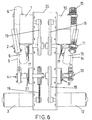
- the second embodiment is similar to the previous one, with the difference that the transmissions of the corresponding motors 1, 3, 10 and 12 are achieved by means of pulleys and belts 19 instead of reducing gears, and that said four motors 1, 3, 10 and 12 are fixed in a common casing 20.
- This second example offers the same massaging possibilities as were indicated above for the first example, though here it is clearly impossible to have independence in displacement of the left-hand motors 1 and 3 with respect to the right-hand motors 10 and 12 as they are mounted in the common casing 20; though on the other hand, there would be no technical inconvenience in dividing or separating the casing 20 into two parts, one for motors 1 and 3, and the other for motors 10 and 12, and effect the displacements by means of two spindles and two independent motors similar to the motors 9 and 16 of the previous example.
- FIG. 7 Another alternative type of motor-shaft transmission, and bearing in mind that this concept is not the object of the patent, is shown in the third embodiment and consists in making use of direct transmission from the rotors of the motors 1, 3, 10 and 12 to the shafts 2, 4, 11 and 13 respectively, as illustrated in figure 7.
- the motors 1, 3, 10 and 12 are mounted in a common casing 21 and all that has been said for the second example is equally applicable to this third embodiment, though it is possible to opt for assembly in independent casings.
- the fourth example of implementation is also similar to the first in so far as operation is concerned, but with the difference that the eccentric shafts 2, 4, 11 and 13 which connect to the massage application elements 5 and 14, are replaced by respective centred shafts 22 which in addition project inwards instead of outwards, such that the four centred shafts 22 face each other two by two.
- Each facing pair of centred shafts 22 is accompanied by a centrally positioned support bearing 23 which connects to said two shafts 22, in such a way that these two shafts 22 provide each other with mutual support but maintain independence with respect to their rotational motion, as illustrated in figure 8.
- an eccentric transmission device 24 is mounted which is connected to the corresponding massage application element 5 or 14.
- this fourth example offers all the advantages and facilities of the first example but with the added advantage that its components have to tolerate less mechanical stress since the rotors of the motors do not suffer the vibrations resulting from the eccentric elements.
Landscapes
- Health & Medical Sciences (AREA)
- Life Sciences & Earth Sciences (AREA)
- Epidemiology (AREA)
- Pain & Pain Management (AREA)
- Physical Education & Sports Medicine (AREA)
- Rehabilitation Therapy (AREA)
- Animal Behavior & Ethology (AREA)
- General Health & Medical Sciences (AREA)
- Public Health (AREA)
- Veterinary Medicine (AREA)
- Dermatology (AREA)
- Massaging Devices (AREA)
- Percussion Or Vibration Massage (AREA)
Abstract
Description
- This invention, as already stated in the abstract to this description, concerns a massage device for a rest armchair, the purpose of which consists of permitting massaging in a completely independent and combined manner on the right-hand and left-hand regions of the back, in both the kneading and tapping modes and in the displacement of the massage-proportioning elements; for this purpose it incorporates four motors governed by a control unit, instead of the two motors typical of conventional massaging chairs.
- Massaging chairs are known which provide massage of the kneading or tapping type employing two motors which transmit their motion to a number of dependent shafts and massaging elements, all this being in such a manner that if the rotation of these motors occurs in one direction then a kneading massage is provided on both sides of the user's back, whilst if the rotation is in the opposite direction a tapping massage is provided on both sides of the back.
- Thus, North American patents numbers 5052376, 5137016 and 5460598 include massage application devices for armchairs, which include two eccentric and inclined shafts, which connect to the actual massage-proportioning elements. These shafts are driven by motors in such a way that the rotation of the motors in one direction results in one type of massage, whilst the rotation in the opposite direction determines another type of massage.
- Moreover, also known are the publications of patent application numbers JP-A-7-323057, WO-A-97/37627, JP-A-02-279157, JP-A-02-172466, JP-A-9-75416, PCT/DE 97/00873 and JP-A-9-38167. All the foregoing applications concern massage devices, but none of them includes four independent motors that can provide an independent massaging effect on the right-hand and left-hand side, as in the case of the invention in question.
- In addition, nor do they permit independent massaging on the right-hand and left-hand sides.
- Finally, these devices clearly cannot regulate/adjust the intensity or speed of massaging on the left-hand side with respect to the right-hand side, or vice versa for the purpose of applying said massages with different intensities or speeds as a function of the taste or therapeutic requirement of the user.
- To achieve the objectives and avoid the inconveniences mentioned above, the invention consists of a massage device for a rest armchair which includes four shafts, two of these being coupled to a massage application device for the left-hand side of the user's back, while the other two are coupled to an massage application element for the right-hand side of the user's back. The invention includes means for: independent massage of the left side or right side of the user, both for kneading and tapping, with the possibility of regulating the intensity or speed on each side in an independent manner; synchronised or unsynchronised massage on both sides of the user's back; variation in the direction of kneading massage on the left-band region; Variation in the direction of kneading massage on the right-hand region; multiple positioning of opening in vertical massage in an independent manner for the left-hand and right-hand regions of the back; and multiple positioning of applied pressure in vertical massage in an independent manner for the left-hand and right-hand regions of the back. According to the invention four independent motors connected to a control unit have been provided for. One of the motors determines a kneading type massage on the left-hand side of the back, another of the motors determines a kneading type massage on the right-hand side of the back, another of the motors determines a tapping type massage on the left-hand side of the back and the other motor determines a tapping type massage on the right-hand side of the back.
- In addition to these four motors there are two motors connected to the aforementioned control unit and to two spindles, one of them for vertical displacement (raising or lowering) of the two previous motors corresponding to the left-hand side and the other for vertical displacement (raising or lowering) of the two previous motors corresponding to the right-hand side.
- Moreover, the four motors first referred to, include position sensors connected to a microprocessor in the control unit in order to know all the time the position of their rotors, granting thereby greater possibilities of control, synchronising or unsynchronising of their movement and the type of massage.
- These motors, spindles and the massage application elements are housed in the back of the corresponding armchair.
- With this configuration, even with one of the motors of the massage armchair faulty, many facilities are still available.
- This configuration permits in a novel and beneficial way the provision of the following types of massage:
- The most important and relevant feature offered by this device is that it permits the intensity or speed on the left-hand side to be operated independently with respect to the right-hand side, or vice versa, as a function of the requirement or therapeutic prescription of the user. To achieve this, use is made of the control unit, which includes conventional means for regulating said balance of intensities or speeds.
- Kneading massage, individualised and synchronised in both directions.
- By putting both kneading motors into operation, right and left, the massage obtained is uniform, on both sides of the back.
- The direction of rotation of the two kneading motors, right and left, can be reversed individually, whereby it is possible to obtain:
- Right-hand and left-hand kneading from inside to outside.
- Right-hand and left-hand kneading from outside to inside.
- Right-hand kneading from inside to outside and left-hand from outside to inside.
- Right-hand kneading from outside to inside and left-hand from inside to outside.
- Tapping massage, individualised and synchronised.
- This type of massage is achieved by putting both tapping motors into operation, left-band and right-band in unison, whereby the massage is obtained on both sides of the back.
- In this type of massage the change of direction in the motor rotation has no sense since no change of massage type is obtained.
- Kneading massage (in both directions) and tapping simultaneously.
- By putting the right-hand and left-hand kneading motors into operation, together with the left-hand and right-hand tapping motors, the two types of massage are obtained at the same time on both sides of the back.
- If the direction of rotation of one or both kneading motors is changed, said massage is performed either from inside to outside or vice versa, on one or on both sides of the back, as a function of the requirements of the person receiving the massage.
- Individual kneading massage of the right-hand region, in both directions.
- This massage is achieved by putting into operation the right-hand kneading motor, in either one or other direction, in order to obtain a massage from inside to outside, or vice versa.
- Individual kneading massage of the left-hand region, in both directions.
- This massage is achieved by putting into operation the right-hand kneading motor only, in either one or other direction, in order to obtain a massage from inside to outside, or vice versa.
- Individual tapping massage of the right-hand region.
- In this case, said massage is achieved by putting into operation the right-hand tapping motor only.
- Individual tapping massage of the left-hand region.
- This massage is achieved on the desired side by putting into operation the left-hand tapping motor only.
- Kneading massage of the right-hand region (in both directions) and tapping massage on the left-hand side.
- This combination of massages is achieved by putting into operation the right-hand kneading motor and the left-hand tapping motor. At the same time it is possible to select the direction of rotation of the kneading motor, in order to obtain a massage either from inside to outside, or vice versa.
- Kneading massage of the left-hand region (in both directions) and tapping massage on the right-hand side.
- This combination of massages is achieved by activating at the same time the left-hand kneading motor and the right-hand tapping motor. At the same time it is possible to select the direction of rotation of the kneading motor, in order to have said massage either from inside to outside, or vice versa.
- Kneading massage, individual and synchronised, in both directions.
- This effect is achieved by means of the position sensor situated on each of the kneading motors, which inform of the position in which each of their two shafts is.
- In this way it is possible to have the right-hand and left-hand kneading shafts rotating with an angular displacement of X degrees, determined by the spacing given on the position sensor plate.
- At the same time as an unsynchronised massage is obtained with all angular displacement of X degrees, it is possible to reverse the direction of rotation of the motors, either in unison or separately, whereby the massage takes place from inside to outside, or vice versa.
- Tapping massage, individual and unsychronised.
- Unsynchronised tapping massage is achieved by mounting on each of the kneading motors, a sensor which monitors the position in which the shaft is located. In this way it is possible to have the right-hand and left-hand tapping shafts rotating with a phase displacement of X degrees, determined by the spacing given on the position sensor plate.
- Various opening options in vertical massage, with or without tapping.
- By means of the position sensors that control the right-hand and left-hand kneading motors, the parking of the opening of the massage wheels is controlled, whereby a multitude of different openings is achieved for the spacing between the right-hand and left-hand massage wheels.
- In this way it is possible to have vertical massage with several different apertures.
- If, at the same time, the tapping massage is actuated, the resulting massage will be performed with a controlled spacing between massage wheels.
- Various pressure applications options in vertical massage, with or without kneading independently.
- By means of the position sensors that control the right-hand and left-hand tapping motors, the parking of the pressure of the eccentrics with respect to the back is controlled.
- In this, way it is possible to perform the vertical massage with a determined pressure as a function of the position in which the position sensor is parked.
- If, in this way, the vertical massage is put into operation, it will take place with the predetermined pressure. If, at the same time, the kneading massage is actuated, either on one or on both sides, and, in one direction or the other, the desired massage combination will be achieved.
- Below, in order to facilitate a better understanding of this description and forming an integral part thereof, a number of figures are attached in which, by way of illustration and in no way limiting, the object of the invention is shown.
-
- Figure 1 shows in schematic form a block diagram of a massage device for a rest armchair implemented according to this invention.
- Figure 2 shows a front view with partial cross-sections of the four kneading and tapping motors that are employed by a massage device for a rest armchair implemented according to this invention.
- Figure 3 shows a side view of a conventional massage application element, which is connected to two of the motors referred to in the previous figure 2.
- Figure 4 shows in a very schematic form the massage device of the invention housed in the corresponding armchair, showing a side view and cross-section of said armchair.
- Figure 5 shows a front view of the same four motors as were referred to in figure 2, but having coupled to them two conventional massage application elements, similar to that referred to in figure 3.
- Figure 6 shows a variant of the invention similar to the previous figure 5 but the transmission taking place through pulley wheels instead of reducing gears, and the four motors being grouped together in a common casing instead of independently.
- Figure 7 shows another variant of the invention similar to the previous figure 6 but the transmission taking place directly from the rotors of the motors to the massage shafts.
- Figure 8 shows a front view, partial and with cross-section, of another variant of the invention, in which the eccentric shafts of the motors are replaced with centred shafts, the necessary eccentricities being obtained by means of additional piece parts.
- Figure 9 shows a perspective view, complete and with cross-section, and with the two details expanded, of the variant of the invention referred to in the previous figure 8.
-
- Below is given a description of four examples of the invention, reference being made to the numbering adopted in the figures.
- Thus, the massage device for a rest armchair of the first embodiment incorporates a left -hand
kneading massage motor 1 which by means of reducing gears transmits the motion of an inclined, eccentric, left-hand shaft 2 and of a left-hand tapping motor 3 which by means of reducing gears transmits the motion to a left-andeccentric shaft 4. - The
shafts massage application element 5 the wheels of which 6 are those which from the inside of thecorresponding armchair 7 are applied to the left-hand part of the user's back. At the same time, all theseelements 1 to 5 can be displaced in a block by aspindle 8 by means of a left-hand displacement motor 9. - Likewise, for the right-hand side the device of this first embodiment incorporates a right-hand
kneading massage motor 10 which by means of reducing gears transmits the motion of an inclined, eccentric, right-hand shaft 11 and a right-hand tapping motor 12 which by means of reducing gears transmits the motion to a right-handeccentric shaft 4. - The
shafts massage application element 14 the wheels of which 15 are those which are applied to the right-hand part of the user's back from the inside of thecorresponding armchair 7. - All these
elements 10 to 15 can be displaced in a block by a spindle (not shown in the figures for being analogous to spindle 8) by means of a right-hand displacement motor 16. - In addition, the four
motors magnetic sensors 17 connected to a microprocessor (not shown in the figures in order to achieve greater clarity) which permit an exact knowledge of the angular position of theshafts - The four motors for kneading and tapping (1, 3, 10 and 12), the displacement motors (9 and 16) and the aforementioned microprocessor are connected to an
electronic control unit 18 which governs the actuation of each of the six motors as a function of the commands it receives, as a function of the position of the mentionedshafts - Thus, depending on the motors that are actuated and according to the direction of rotation they are given, all the types of massage described in the section "DESCRIPTION OF THE INVENTION" are made possible, these are:
- Individualised, synchronised kneading massage, in both
directions (
motors 1 and 10). - Individualised, synchronised tapping massage (
motors 3 and 12). - Kneading massage in both directions with tapping at the
same time (
motors - Individualised kneading massage on the right-hand region, in both directions (motor 10).
- Individualised kneading massage on the left-hand region, in both directions (motor 1).
- Individualised tapping massage on the right-band region (motor 12).
- Individualised tapping massage on the left-band region (motor 3).
- Kneading massage in the right-hand region in both
directions, and tapping on the right (
motors 1 and 12). - Kneading massage, individualised and unsynchronised in
both directions (
sensors 17 of themotors 1 and 10). - Tapping massage, individualised and unsynchronised
(
sensors 17 of themotors 3 and 12). - Three opening options in vertical massage, with or
without tapping (
sensors 17 of themotors 1 and 10). - Three pressure options in vertical massage, with or
without kneading (
sensors 17 of themotors 3 and 12). - The second embodiment is similar to the previous one, with the difference that the transmissions of the
corresponding motors belts 19 instead of reducing gears, and that said fourmotors common casing 20. - Logically, in this case, there is only one spindle with a displacement motor that has not been shown in the figures for being analogous to the
elements - This second example offers the same massaging possibilities as were indicated above for the first example, though here it is clearly impossible to have independence in displacement of the left-
hand motors hand motors common casing 20; though on the other hand, there would be no technical inconvenience in dividing or separating thecasing 20 into two parts, one formotors motors motors - Another alternative type of motor-shaft transmission, and bearing in mind that this concept is not the object of the patent, is shown in the third embodiment and consists in making use of direct transmission from the rotors of the
motors shafts motors common casing 21 and all that has been said for the second example is equally applicable to this third embodiment, though it is possible to opt for assembly in independent casings. - Logically, as well as the motor-shaft transmissions by means of reducing gears, pulleys or directly, it is possible to make use of any other type of transmission existing or that may be developed in the future and which is suitable for application to this invention.
- The fourth example of implementation is also similar to the first in so far as operation is concerned, but with the difference that the
eccentric shafts massage application elements shafts 22 which in addition project inwards instead of outwards, such that the fourcentred shafts 22 face each other two by two. - Each facing pair of
centred shafts 22 is accompanied by a centrally positioned support bearing 23 which connects to said twoshafts 22, in such a way that these twoshafts 22 provide each other with mutual support but maintain independence with respect to their rotational motion, as illustrated in figure 8. - Finally, on each of the four
centred shafts 22 aneccentric transmission device 24 is mounted which is connected to the correspondingmassage application element - With this configuration, this fourth example offers all the advantages and facilities of the first example but with the added advantage that its components have to tolerate less mechanical stress since the rotors of the motors do not suffer the vibrations resulting from the eccentric elements.
Claims (9)
- MASSAGE DEVICE FOR A REST ARMCHAIR, which incorporates four shafts (2, 4, 11 and 13, or 22), two of these being coupled to a massage application element (5) for the left-hand side of the user's back, while the other two are coupled to a massage application device (14) for the right-hand side of the user's back; characterised in that they count with means for:independent massage for the left-hand or right-hand side of the user, for both kneading and tapping, with the possibility of regulating the intensity or speed on each side in an independent manner;synchronised or unsynchronised massage on both sides of the user's back;variation in the kneading massaging direction on the left-hand region;variation in the kneading massaging direction on the right-hand region;multiple positioning of opening for vertical massaging in an independent manner for the left-hand and right-hand regions of the back, andmultiple positioning of pressure for vertical massaging in an independent manner for the left-hand and right-hand regions of the back.
- MASSAGE DEVICE FOR A REST ARMCHAIR, in accordance with claim 1, characterised in that said means consist of:a left-band kneading motor (1) which transmits rotation to a first of said four shafts,a right-hand kneading motor (1) which transmits rotation to a second of said four shafts,a left-hand tapping motor (3) which transmits rotation to a third of said four shafts,a right-hand tapping motor (12) which transmits rotation to a fourth of said four shafts,a number of sensors (17) of the angular position of said four shafts, connected to a microprocessor, anda control unit (18) through which said microprocessor and the four motors (1, 3, 10, 12) are connected;
being independent the motors (1, 3, 10 and 12) referred to. - MASSAGE DEVICE FOR A REST ARMCHAIR, in accordance with claim 2, characterised in that to the control unit (18) is also connected a left-hand displacement motor (9) which enables joint vertical displacement via by means of a spindle (8) of the motors for left-hand kneading massage (1) and left-hand tapping massage (3); being also connected to said control unit (18) a right-hand displacement motor (16) which enables joint vertical displacement via another spindle of the motors for right-hand kneading massage (10) and right-hand tapping massage (12).
- MASSAGE DEVICE FOR A REST ARMCHAIR, in accordance with claim 2, characterised in that the four motors referred to (1, 3, 10 and 12) are able to be fixed in a common casing (20 or 21), in which case there is a single vertical displacement motor via a spindle which connects with the control unit (18).
- MASSAGE DEVICE FOR A REST ARMCHAIR, in accordance with claims 1 or 2, characterised in that said four shafts are four centred shafts (22) which project towards the inside and which are facing each other two by two; there being between each pair of centred facing shafts (22) a support bearing (23) which connects to the shafts (22) of the corresponding pair, whereby said two shafts (22) provide each other with mutual support maintaining their rotational motions independent; and being located over each of the four centred shafts (22) an eccentric transmission device (24) which is connected to the corresponding massage application element (5 or 14).
- MASSAGE DEVICE FOR A REST ARMCHAIR, in accordance with claim 2, characterised in that said four shafts are one left-hand, inclined and eccentric shaft (2), one right-band, inclined and eccentric shaft (11), one left-hand eccentric shaft (4) and one right-hand eccentric shaft (13); being respectively connected these shafts (2, 11, 4 and 13) to the left-hand kneading massaging motor (1), the right-hand kneading massaging motor (10), the left-hand tapping massaging motor (3) and the right-hand tapping massaging motor (12).
- MASSAGE DEVICE FOR A REST ARMCHAIR, in accordance with claim 6, characterised in that the rotational transmissions of the motors referred to (1, 3, 10 and 12) to the aforementioned shafts (2, 4, 11, and 13) are achieved by means of reducing gears.
- MASSAGE DEVICE FOR A REST ARMCHAIR, in accordance with claim 6, characterised in that the rotational transmissions of the motors referred to (1, 3, 10 and 12) to the aforementioned shafts (2, 4, 11 and 13) are achieved by means of pulleys and belts (19).
- MASSAGE DEVICE FOR A REST ARMCHAIR, in accordance with claim 6, characterised in that the rotational transmissions of the motors referred to (1, 3, 10 and 12) to the aforementioned shafts (2, 4, 11, 13) are achieved directly by means of the rotors of said motors (1, 3, 10 and 12).
Applications Claiming Priority (3)
| Application Number | Priority Date | Filing Date | Title |
|---|---|---|---|
| ES009701318A ES2151351B1 (en) | 1997-06-17 | 1997-06-17 | MASSAGE DEVICE FOR REST ARMCHAIR. |
| ES9701318 | 1997-06-17 | ||
| PCT/ES1998/000172 WO1998057611A1 (en) | 1997-06-17 | 1998-06-16 | Massasing device for a rest armchair |
Publications (2)
| Publication Number | Publication Date |
|---|---|
| EP1013254A1 true EP1013254A1 (en) | 2000-06-28 |
| EP1013254B1 EP1013254B1 (en) | 2001-10-31 |
Family
ID=8299710
Family Applications (1)
| Application Number | Title | Priority Date | Filing Date |
|---|---|---|---|
| EP98925642A Expired - Lifetime EP1013254B1 (en) | 1997-06-17 | 1998-06-16 | Massaging device for a rest armchair |
Country Status (8)
| Country | Link |
|---|---|
| US (1) | US6443917B1 (en) |
| EP (1) | EP1013254B1 (en) |
| JP (1) | JP2002504845A (en) |
| CN (1) | CN1245148C (en) |
| CA (1) | CA2294596A1 (en) |
| DE (1) | DE69802299T2 (en) |
| ES (2) | ES2151351B1 (en) |
| WO (1) | WO1998057611A1 (en) |
Cited By (4)
| Publication number | Priority date | Publication date | Assignee | Title |
|---|---|---|---|---|
| EP1362571A3 (en) * | 2002-05-14 | 2004-01-07 | Omron Corporation | Massaging machine |
| WO2005097037A1 (en) * | 2004-04-08 | 2005-10-20 | OKIN Gesellschaft für Antriebstechnik mbH | Massage arm |
| EP1738736A1 (en) * | 2005-06-29 | 2007-01-03 | Ciar S.P.A. | Massage device for furniture for sitting or reclining |
| CN102151214A (en) * | 2011-03-14 | 2011-08-17 | 杭州兴达机械有限公司 | Massage shaft and processing method thereof |
Families Citing this family (29)
| Publication number | Priority date | Publication date | Assignee | Title |
|---|---|---|---|---|
| DE29823109U1 (en) | 1998-12-28 | 1999-04-08 | Krautmann Bernhard | Drive device for a massage chair |
| JP3694616B2 (en) * | 1999-07-07 | 2005-09-14 | フランスベッド株式会社 | Massage equipment |
| JP4249872B2 (en) * | 1999-09-09 | 2009-04-08 | ファミリー株式会社 | Massage machine |
| JP4020581B2 (en) * | 2000-11-15 | 2007-12-12 | 三洋電機株式会社 | Chair type massage machine |
| JP4017350B2 (en) * | 2001-02-09 | 2007-12-05 | 三洋電機株式会社 | Massage machine |
| JP2002282318A (en) * | 2001-03-26 | 2002-10-02 | Family Kk | Massage machine |
| JP2003225271A (en) * | 2002-01-31 | 2003-08-12 | Sanyo Electric Co Ltd | Massage machine |
| EP1386595B1 (en) * | 2002-08-01 | 2004-10-20 | Ciar S.P.A. | Massage device |
| US7022092B2 (en) * | 2003-02-28 | 2006-04-04 | Daito Electric Machine Industry Company Limited | Four massaging head type massaging mechanism and massaging apparatus incorporating the same |
| US7770965B2 (en) * | 2003-04-09 | 2010-08-10 | Shane Zwezdaryk | Chair |
| DE202004003066U1 (en) * | 2004-02-25 | 2004-06-03 | OKIN Gesellschaft für Antriebstechnik mbH & Co. KG | massage carriage |
| US20110184324A1 (en) * | 2004-05-11 | 2011-07-28 | Weightec Electronic Technology Co., Ltd. | Massage device |
| US20100268132A1 (en) * | 2004-05-11 | 2010-10-21 | Chichun Wu | Massage device |
| US8414510B2 (en) * | 2004-05-11 | 2013-04-09 | Chichun Wu | Massage device with a massage head distance adjusting mechanism |
| CN2707246Y (en) * | 2004-05-11 | 2005-07-06 | 武济群 | massager structure |
| US7470242B2 (en) | 2005-03-18 | 2008-12-30 | Fka Distributing Co. | Portable body massager having width adjustable massage members on translating carriage |
| JP4661302B2 (en) * | 2005-03-28 | 2011-03-30 | パナソニック電工株式会社 | Massage machine |
| JP2007029481A (en) * | 2005-07-28 | 2007-02-08 | Family Co Ltd | Massage machine |
| KR100932591B1 (en) * | 2005-07-28 | 2009-12-17 | 파나소닉 전공 주식회사 | Massager |
| ES2288787B1 (en) * | 2005-08-26 | 2008-12-01 | Eurokeyton, S.A. | MASSAGE DEVICE. |
| CN101002711B (en) * | 2006-01-18 | 2011-03-30 | 松下电工株式会社 | Massaging device |
| WO2009019750A1 (en) * | 2007-08-03 | 2009-02-12 | Panasonic Electric Works Co., Ltd. | Massage machine |
| WO2009146351A1 (en) * | 2008-05-28 | 2009-12-03 | Fka Distributing Co. D/B/A Homedics, Inc. | Body massagers |
| CN107072868B (en) * | 2014-10-24 | 2020-11-06 | 发美利稻田株式会社 | massage machine |
| JP6279517B2 (en) * | 2015-06-24 | 2018-02-14 | 大東電機工業株式会社 | Massage mechanism and sitting chair type massage machine equipped with this massage mechanism |
| JP7231182B2 (en) * | 2018-07-23 | 2023-03-01 | ファミリーイナダ株式会社 | Treatment unit and massage machine using the treatment unit |
| CN109589253B (en) * | 2018-12-06 | 2024-03-12 | 奥佳华智能健康科技集团股份有限公司 | Force-adaptive massage movement and massage chair |
| CA3063455A1 (en) * | 2019-11-29 | 2021-05-29 | Aurum Management Corp. | Reciprocating massage table |
| KR102863620B1 (en) * | 2024-01-31 | 2025-09-24 | 주식회사 바디프랜드 | Leg massage part connecting device of massage device |
Family Cites Families (10)
| Publication number | Priority date | Publication date | Assignee | Title |
|---|---|---|---|---|
| US3322116A (en) * | 1964-02-13 | 1967-05-30 | Frank M Murphy | Vibratory massage apparatus |
| JPS518789A (en) * | 1974-07-11 | 1976-01-23 | Nichimu Inada | Matsusaajiki |
| US4718408A (en) * | 1986-04-29 | 1988-01-12 | Armando Barreiro | Variable massage apparatus having a clutch selectively engaging alternate gears |
| US5052376A (en) * | 1989-09-15 | 1991-10-01 | Kabushiki Kaisha Fuji Iryoki | Drive section for automatic massaging apparatus |
| US5020518A (en) * | 1990-02-09 | 1991-06-04 | Integrity Health Systems Corporation | Travelling roller massage apparatus |
| US5462516A (en) * | 1993-12-29 | 1995-10-31 | Niagara Therapy Manufacturing, Inc. | Cyclical action massaging chair |
| WO1996001610A1 (en) * | 1994-07-12 | 1996-01-25 | France Bed Co., Ltd. | Massaging apparatus |
| ES2160937T5 (en) * | 1996-04-04 | 2009-11-13 | Ciar S.P.A. | MASSAGE DEVICE FOR INSERTION IN THE BACKUP OF MASSAGE OR SIMILAR CHAIRS. |
| TW364846B (en) * | 1996-05-27 | 1999-07-21 | Sanyo Electric Co | Chair type massage machine |
| TW358026B (en) * | 1996-09-30 | 1999-05-11 | Sanyo Electric Co | Massage apparatus |
-
1997
- 1997-06-17 ES ES009701318A patent/ES2151351B1/en not_active Expired - Lifetime
-
1998
- 1998-06-16 CN CNB988063506A patent/CN1245148C/en not_active Expired - Fee Related
- 1998-06-16 CA CA002294596A patent/CA2294596A1/en not_active Abandoned
- 1998-06-16 WO PCT/ES1998/000172 patent/WO1998057611A1/en not_active Ceased
- 1998-06-16 US US09/446,178 patent/US6443917B1/en not_active Expired - Fee Related
- 1998-06-16 EP EP98925642A patent/EP1013254B1/en not_active Expired - Lifetime
- 1998-06-16 JP JP50382899A patent/JP2002504845A/en active Pending
- 1998-06-16 ES ES98925642T patent/ES2165167T3/en not_active Expired - Lifetime
- 1998-06-16 DE DE69802299T patent/DE69802299T2/en not_active Expired - Fee Related
Non-Patent Citations (1)
| Title |
|---|
| See references of WO9857611A1 * |
Cited By (4)
| Publication number | Priority date | Publication date | Assignee | Title |
|---|---|---|---|---|
| EP1362571A3 (en) * | 2002-05-14 | 2004-01-07 | Omron Corporation | Massaging machine |
| WO2005097037A1 (en) * | 2004-04-08 | 2005-10-20 | OKIN Gesellschaft für Antriebstechnik mbH | Massage arm |
| EP1738736A1 (en) * | 2005-06-29 | 2007-01-03 | Ciar S.P.A. | Massage device for furniture for sitting or reclining |
| CN102151214A (en) * | 2011-03-14 | 2011-08-17 | 杭州兴达机械有限公司 | Massage shaft and processing method thereof |
Also Published As
| Publication number | Publication date |
|---|---|
| WO1998057611A1 (en) | 1998-12-23 |
| EP1013254B1 (en) | 2001-10-31 |
| CN1245148C (en) | 2006-03-15 |
| JP2002504845A (en) | 2002-02-12 |
| US6443917B1 (en) | 2002-09-03 |
| ES2151351B1 (en) | 2001-06-16 |
| CN1260705A (en) | 2000-07-19 |
| ES2165167T3 (en) | 2002-03-01 |
| DE69802299D1 (en) | 2001-12-06 |
| CA2294596A1 (en) | 1998-12-23 |
| ES2151351A1 (en) | 2000-12-16 |
| DE69802299T2 (en) | 2002-07-25 |
Similar Documents
| Publication | Publication Date | Title |
|---|---|---|
| EP1013254B1 (en) | Massaging device for a rest armchair | |
| US4777940A (en) | Portable massaging apparatus having vibration isolating members on worm gears | |
| US4167182A (en) | Massage apparatus | |
| JP2002345914A (en) | Massage machine | |
| JP2612120B2 (en) | Massage machine | |
| EP4035643B1 (en) | Massage device | |
| KR200456153Y1 (en) | Massage chair having independently controllable massagers | |
| KR102897883B1 (en) | module of Physiotherapy | |
| JPH0113856B2 (en) | ||
| JP3861626B2 (en) | Massage machine controller | |
| JPH0759825A (en) | Massage machine | |
| JP2000217879A (en) | Massager | |
| CN221154689U (en) | Massage assembly and massage instrument thereof | |
| JP2935766B2 (en) | Massage machine | |
| JP3099007U (en) | Foot massage equipment | |
| JP2721526B2 (en) | Massage machine | |
| JP3274897B2 (en) | Massage machine | |
| JPH04327047A (en) | Epicyclic reduction gear | |
| JP2702763B2 (en) | Massage machine | |
| JP2520413Y2 (en) | Massage machine | |
| JPS6021063Y2 (en) | Belt pine surge machine | |
| JPH10234802A (en) | Rubbing machine | |
| JPH10213189A (en) | Shift mechanism | |
| JPH11137623A (en) | Massager | |
| JPH05253266A (en) | Massager |
Legal Events
| Date | Code | Title | Description |
|---|---|---|---|
| PUAI | Public reference made under article 153(3) epc to a published international application that has entered the european phase |
Free format text: ORIGINAL CODE: 0009012 |
|
| 17P | Request for examination filed |
Effective date: 20000117 |
|
| AK | Designated contracting states |
Kind code of ref document: A1 Designated state(s): BE CH DE DK ES FR GB IT LI NL PT SE |
|
| GRAG | Despatch of communication of intention to grant |
Free format text: ORIGINAL CODE: EPIDOS AGRA |
|
| 17Q | First examination report despatched |
Effective date: 20001117 |
|
| GRAG | Despatch of communication of intention to grant |
Free format text: ORIGINAL CODE: EPIDOS AGRA |
|
| GRAH | Despatch of communication of intention to grant a patent |
Free format text: ORIGINAL CODE: EPIDOS IGRA |
|
| GRAH | Despatch of communication of intention to grant a patent |
Free format text: ORIGINAL CODE: EPIDOS IGRA |
|
| GRAA | (expected) grant |
Free format text: ORIGINAL CODE: 0009210 |
|
| AK | Designated contracting states |
Kind code of ref document: B1 Designated state(s): BE CH DE DK ES FR GB IT LI NL PT SE |
|
| PG25 | Lapsed in a contracting state [announced via postgrant information from national office to epo] |
Ref country code: NL Free format text: LAPSE BECAUSE OF FAILURE TO SUBMIT A TRANSLATION OF THE DESCRIPTION OR TO PAY THE FEE WITHIN THE PRESCRIBED TIME-LIMIT Effective date: 20011031 Ref country code: LI Free format text: LAPSE BECAUSE OF FAILURE TO SUBMIT A TRANSLATION OF THE DESCRIPTION OR TO PAY THE FEE WITHIN THE PRESCRIBED TIME-LIMIT Effective date: 20011031 Ref country code: CH Free format text: LAPSE BECAUSE OF FAILURE TO SUBMIT A TRANSLATION OF THE DESCRIPTION OR TO PAY THE FEE WITHIN THE PRESCRIBED TIME-LIMIT Effective date: 20011031 Ref country code: BE Free format text: LAPSE BECAUSE OF FAILURE TO SUBMIT A TRANSLATION OF THE DESCRIPTION OR TO PAY THE FEE WITHIN THE PRESCRIBED TIME-LIMIT Effective date: 20011031 |
|
| REG | Reference to a national code |
Ref country code: CH Ref legal event code: EP |
|
| REF | Corresponds to: |
Ref document number: 69802299 Country of ref document: DE Date of ref document: 20011206 |
|
| REG | Reference to a national code |
Ref country code: GB Ref legal event code: IF02 |
|
| PG25 | Lapsed in a contracting state [announced via postgrant information from national office to epo] |
Ref country code: SE Free format text: LAPSE BECAUSE OF FAILURE TO SUBMIT A TRANSLATION OF THE DESCRIPTION OR TO PAY THE FEE WITHIN THE PRESCRIBED TIME-LIMIT Effective date: 20020131 Ref country code: PT Free format text: LAPSE BECAUSE OF FAILURE TO SUBMIT A TRANSLATION OF THE DESCRIPTION OR TO PAY THE FEE WITHIN THE PRESCRIBED TIME-LIMIT Effective date: 20020131 Ref country code: DK Free format text: LAPSE BECAUSE OF FAILURE TO SUBMIT A TRANSLATION OF THE DESCRIPTION OR TO PAY THE FEE WITHIN THE PRESCRIBED TIME-LIMIT Effective date: 20020131 |
|
| REG | Reference to a national code |
Ref country code: ES Ref legal event code: FG2A Ref document number: 2165167 Country of ref document: ES Kind code of ref document: T3 |
|
| ET | Fr: translation filed | ||
| NLV1 | Nl: lapsed or annulled due to failure to fulfill the requirements of art. 29p and 29m of the patents act | ||
| REG | Reference to a national code |
Ref country code: CH Ref legal event code: PL |
|
| PLBE | No opposition filed within time limit |
Free format text: ORIGINAL CODE: 0009261 |
|
| STAA | Information on the status of an ep patent application or granted ep patent |
Free format text: STATUS: NO OPPOSITION FILED WITHIN TIME LIMIT |
|
| 26N | No opposition filed | ||
| PG25 | Lapsed in a contracting state [announced via postgrant information from national office to epo] |
Ref country code: FR Free format text: LAPSE BECAUSE OF NON-PAYMENT OF DUE FEES Effective date: 20030228 |
|
| REG | Reference to a national code |
Ref country code: FR Ref legal event code: ST |
|
| PGFP | Annual fee paid to national office [announced via postgrant information from national office to epo] |
Ref country code: GB Payment date: 20040616 Year of fee payment: 7 |
|
| PG25 | Lapsed in a contracting state [announced via postgrant information from national office to epo] |
Ref country code: GB Free format text: LAPSE BECAUSE OF NON-PAYMENT OF DUE FEES Effective date: 20050616 |
|
| GBPC | Gb: european patent ceased through non-payment of renewal fee |
Effective date: 20050616 |
|
| PGFP | Annual fee paid to national office [announced via postgrant information from national office to epo] |
Ref country code: IT Payment date: 20060630 Year of fee payment: 9 |
|
| PGFP | Annual fee paid to national office [announced via postgrant information from national office to epo] |
Ref country code: DE Payment date: 20060803 Year of fee payment: 9 |
|
| PGFP | Annual fee paid to national office [announced via postgrant information from national office to epo] |
Ref country code: ES Payment date: 20070613 Year of fee payment: 10 |
|
| PG25 | Lapsed in a contracting state [announced via postgrant information from national office to epo] |
Ref country code: DE Free format text: LAPSE BECAUSE OF NON-PAYMENT OF DUE FEES Effective date: 20080101 |
|
| REG | Reference to a national code |
Ref country code: ES Ref legal event code: FD2A Effective date: 20080617 |
|
| PG25 | Lapsed in a contracting state [announced via postgrant information from national office to epo] |
Ref country code: IT Free format text: LAPSE BECAUSE OF NON-PAYMENT OF DUE FEES Effective date: 20070616 |
|
| PG25 | Lapsed in a contracting state [announced via postgrant information from national office to epo] |
Ref country code: ES Free format text: LAPSE BECAUSE OF NON-PAYMENT OF DUE FEES Effective date: 20080617 |