EP1013145B1 - Electric heaters - Google Patents
Electric heaters Download PDFInfo
- Publication number
- EP1013145B1 EP1013145B1 EP98904302A EP98904302A EP1013145B1 EP 1013145 B1 EP1013145 B1 EP 1013145B1 EP 98904302 A EP98904302 A EP 98904302A EP 98904302 A EP98904302 A EP 98904302A EP 1013145 B1 EP1013145 B1 EP 1013145B1
- Authority
- EP
- European Patent Office
- Prior art keywords
- heater
- actuator
- control unit
- control
- track
- Prior art date
- Legal status (The legal status is an assumption and is not a legal conclusion. Google has not performed a legal analysis and makes no representation as to the accuracy of the status listed.)
- Expired - Lifetime
Links
Images


Classifications
-
- H—ELECTRICITY
- H05—ELECTRIC TECHNIQUES NOT OTHERWISE PROVIDED FOR
- H05B—ELECTRIC HEATING; ELECTRIC LIGHT SOURCES NOT OTHERWISE PROVIDED FOR; CIRCUIT ARRANGEMENTS FOR ELECTRIC LIGHT SOURCES, IN GENERAL
- H05B1/00—Details of electric heating devices
- H05B1/02—Automatic switching arrangements specially adapted to apparatus ; Control of heating devices
- H05B1/0202—Switches
- H05B1/0213—Switches using bimetallic elements
-
- A—HUMAN NECESSITIES
- A47—FURNITURE; DOMESTIC ARTICLES OR APPLIANCES; COFFEE MILLS; SPICE MILLS; SUCTION CLEANERS IN GENERAL
- A47J—KITCHEN EQUIPMENT; COFFEE MILLS; SPICE MILLS; APPARATUS FOR MAKING BEVERAGES
- A47J27/00—Cooking-vessels
- A47J27/21—Water-boiling vessels, e.g. kettles
- A47J27/21008—Water-boiling vessels, e.g. kettles electrically heated
- A47J27/21058—Control devices to avoid overheating, i.e. "dry" boiling, or to detect boiling of the water
- A47J27/21066—Details concerning the mounting thereof in or on the water boiling vessel
-
- H—ELECTRICITY
- H05—ELECTRIC TECHNIQUES NOT OTHERWISE PROVIDED FOR
- H05B—ELECTRIC HEATING; ELECTRIC LIGHT SOURCES NOT OTHERWISE PROVIDED FOR; CIRCUIT ARRANGEMENTS FOR ELECTRIC LIGHT SOURCES, IN GENERAL
- H05B3/00—Ohmic-resistance heating
- H05B3/78—Heating arrangements specially adapted for immersion heating
- H05B3/82—Fixedly-mounted immersion heaters
Definitions
- the present invention relates to an electric heater assembly for a liquid heating apparatus and a thermally sensitive control unit for use therewith.
- liquid heating vessels such as kettles and hot water jugs were normally provided with heaters in the form of sheathed heating elements which extended into the vessel through an opening in the side wall or the base of the vessel.
- Such elements are, however, prone to 'furring' in hard water areas, are difficult to clean, and also make the inside of the vessel more difficult to clean.
- heaters in liquid heating vessels.
- These heaters comprise an electrically resistive heating track deposited, for example printed, on an electrically insulating substrate provided typically on a metallic support plate.
- the metallic support plate may be the base of the vessel itself, or a plate for mounting in the base of the vessel. Examples of such heaters are shown, for example in WO96/18331 and WO96/17497.
- the thick film heating track has a tortuous path terminating in a pair of terminals through which power is supplied to the track.
- the power is normally supplied via a thermally sensitive control unit which acts to open a set of contacts in the controls unit to disconnect the power supply to the track in the event, for example, that the heater overheats.
- the thermally sensitive control may, for example, comprise an overheat protection control which operates in the event that the heater overheats and/or a boiling control which operates in the event that liquid in a liquid heating vessel boils.
- the control may comprise a thermally sensitive actuator, such as a bimetallic actuator, which is arranged in good thermal contact with a portion of the heater or the liquid in the vessel.
- thermally sensitive switch units including an actuator and switch contacts have been resiliently biased against the heater. This is expensive as the leads to the control need to be flexible to take up the movement.
- a thermally deformable plastics carrier for a bimetallic actuator is resiliently biased against a part of the heater.
- the biasing is intended primarily to pre-load a back-up protection mechanism which operates in the event that the bimetallic actuator fails to operate. The biasing force produced is quite substantial and if transmitted directly to the actuator could adversely interfere with its operation.
- the present invention seeks to overcome this problem, and provides a thermally sensitive control unit for interrupting the electrical supply to a thick film electric heater forming, or forming a part of the base of a water boiling vessel in the event of said heater overheating, said control unit comprising a thermally sensitive bimetallic actuator mounted to the control unit by a resilient carrier, the actuator being mounted to and carried by said carrier and said carrier being mounted to a mounting location on said control unit such that in use the thermally sensitive actuator is resiliently biased against said heater by said carrier so as to accommodate deformation of the heater during operation and relative movement of the mounting location and the heater, said resilient bias being light so as not adversely to interfere with the operation of the actuator.
- the spring force biasing the actuator into contact with the heater can be set to produce the requisite biasing force without interfering with the operation of the actuator.
- the resilient mounting will be able to accommodate deformation of the heater and mounting tolerances.
- any suitable spring may be used as the resilient carrier to mount the actuator but preferably a leaf spring is used. In a particularly preferred embodiment, a frame-like spring is used.
- biasing force is arranged to be less than 100g, more preferably less than 50g.
- the mounting is such that the actuator engages with the heater substantially around the whole periphery of the actuator, so as to give better thermal contact with the heater.
- the actuator is a bimetallic actuator, most preferably a snap acting bimetallic actuator, for example of the type disclosed in GB 1542252.
- Such actuators are formed with a central cut out which defines a tongue, and preferably the actuator is mounted to the control unit by a leaf spring engaging with the tongue.
- liquid heating apparatus including a control or an assembly in accordance with the invention, more particularly to such apparatus wherein the control is mounted under the base of the apparatus, more particularly to a heater forming or forming a part of the base of a liquid heating vessel.
- the invention provides a heater assembly in or for a liquid heating apparatus comprising a thick-film electric heater and the thermally sensitive control unit according to claim 1.
- heaters are now typically formed on a plate for mounting in the base of a vessel, for example a plastics vessel, and on which the thick film or sheathed element is provided. It has proved particularly difficult to provide satisfactory mounting of a heater plate in the base of a plastics vessel, since it is difficult to provide a sufficient depth of plastics material into which to secure fixing means such as screws.
- the control is mounted to the vessel body as to clamp the plate between the control and the vessel, with sealing means interposed between the heater and the vessel.
- the base of the vessel is provided with a number of mounting bosses over which locate a number of bores provided around the periphery of the control.
- One end of each bore engages the heater around the base of the boss, and clamping screws or the like tighten against the other end of the bore.
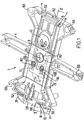
- a control unit 2 embodying the invention comprises four main moulded plastics parts namely a tray-like body part 4, a trip lever 6, a cover plate 8 and a knob moulding 10.
- the control is intended for use with a thick film heater 200 having a stainless steel plate 202 on which is deposited an insulating glass layer (not referenced), on top of which is a tortuous heating track 204.
- the heating track 204 is provided with a pair of contacts 206, 208 through which power may be supplied to the track.
- the plate 202 is provided with a central sump 210 which may be formed as a separate part and joined to the plate, for example, by discharge welding.
- control unit 2 heater is shown upside down in Figures 2, 5, 6, 7 and 8.
- the trip lever 6 (some of whose detail is shown in phantom lines in Figure 1 and which is described more fully in Figures 3 and 4) is pivotally mounted at one of its ends to one end of the body 4 via knife edges 12 which engage in corresponding V-grooves 14 provided in the control body 4.
- the trip lever 6 is an over centre mechanism which is biased between two stable position by a C-spring 16 mounted between V grooves 18, 20 provided in the trip lever 6 (see Fig. 4) and body control body 4 (Fig. 2) respectively.
- the C-spring 16 also acts to bias the knife edges 12 into the grooves 14 on the body part 4.
- the trip lever 6 is provided with a pair of laterally extending pins 22, 24 which are received in slots 26, 28 provided in one end of the generally U-shaped knob moulding 10 whose arms 30, 32 in use extend outside the base of the vessel for manipulation by a user.
- the arms 30, 32 are provided with journals 34, 36 which fit over mounting bosses 38, 40 provided on the body part 4. This will allow the knob moulding 10 to pivot in the opposite direction to the movement of the trip lever 6.
- the trip lever also mounts a pair of snap-acting bimetallic actuators 42, 44 of the type described in GB-A-1542252.
- the first bimetallic actuator 42 which constitutes an overheat protection actuator, is mounted on a pillar 46 provided on the side of the trip lever 6 which, in use faces the heater 200.
- the actuator 42 is mounted to the pillar 44 via a frame-like spring 48 having a first end 50 which engages over the pillar 46 and which clicks into position under a pair of lugs 52, 54, and a second end with an opening 56 through which extends the central tongue 58 of the actuator 42.
- the side arms 60, 62 of the spring 48 act resiliently to bias the periphery of the actuator 42 against the heater 200 as will be described further below.
- the trip lever 6 is also provided with an aperture 64 through which, in use, the sump 210 of the heater extends.
- a second pillar 66 is provided on the other side of the trip lever 6 adjacent the aperture 64, and which mounts the second bimetallic actuator 44.
- the pillar 66 has a pair of laterally extending lugs 67 under which a slot 69 in spring 49 (see Fig. 2) may engage.
- this actuator 44 will, in use, sense when liquid in a vessel boils.
- trip lever arm 6 is also provided with a pair of slots 70, 72 and a pair of contact lifting surfaces 74, 76.
- the control body 4 is moulded with an inlet 100 for a power cord (not shown), the inlet receiving line, neutral and earth terminal pins 102, 104, 106 in a standard configuration.
- the pins 102, 104, 106 extend through the rear wall 108 of the inlet and are riveted to respective leaf springs 110, 112, 114.
- the leaf springs 110, 112 which are connected to the live or neutral pins 102, 104 mount contacts 116, 118 which, will make contact with the fixed contacts 202, 204 provided on the heater 200.
- the earth leaf spring 114 is bent around the inlet 100 and has a tongue 120 for earthing engagement with a slot 212 in the heater plate.
- the control body 4 has a central aperture 122 in which provides access to the sump 210 of the heater.
- the aperture 122 is surrounded by a flange 124 which receives a dished copper mounting plate 126 having a central planar bottom 128 and an inclined periphery 132.
- the flat bottom 128 rests on the flange 124, and the plate 126 is retained in position on the sump by a plurality of legs 134 pressed out from the plate 126.
- a plurality of lugs 130 retain the plate 126 on the control body 4.
- the bottom 128 of the plate 126 acts as a mounting location for the bimetallic actuator 44.
- the aperture 122 in the body 4 is extended into a slot 136, and the plate is provided with a slot 138 through which the mounting pillar 66 for the actuator 42 may pass.
- the control body 4 is also provided with a number of bores 150 arranged around its periphery for mounting to the bottom of a vessel.
- the bores 150 have a closed end 153 against which a fastener such as a screw may clamp, and the other end of the bore engages with the heater, as will be described further below.
- it is provided with four grooves 152 into which T-shaped tongues 214 of the heater 200 may be folded in order correctly to position the control with respect to the heater 200.
- a number of bosses 156 are also provided on the control body 4 for mounting a cover moulding to the vessel.
- control body 4 has four slots for receiving mounting clips 180 of the cover plate 8.
- cover plate 8 this is generally planar, but with a number of apertures and upstanding features.
- the contact has a pair of apertures 160, 162 (not shown in Fig. 2) behind which are arranged the line and neutral contacts 116, 118 of the control.
- the contacts In the unmounted state, the contacts may be positioned within, or may protrude slightly from the apertures 160, 162 depending on the size of the contacts provided on the heater. The arrangement should be such that upon assembly, the respective contacts engage with one another with a sufficient contact force.
- the spring leaves mounting the contacts 116, 118 may engage the inner edge of the apertures 160,162 to set the position of, and pre-load, the contacts 116,118 prior to mounting to the heater.
- Respective rims 164, 166 are raised around the apertures 160, 162 for engagement with the surface of the heater.
- the apertures 160, 162 and the rims 164, 166 form an enclosure around the contacts in use, as shown in Figure 5, for example to shield the heater and other parts of the control from arcing.
- the cover plate 8 has a larger aperture 170 through which the sump 210 of the heater can extend.
- a rim 172 of the same height as the rims 164, 166 is raised around the aperture 170 on the heater-facing side of the cover plate for engagement with the surface of the heater 200.
- On the other side of the cover plate 8 a generally cylindrical wall 174 is raised which in use extends around the sump 210 of the heater 200, so as to shield the sump from arcing.
- the internal surface of the wall 174 is provided with grooves 176 to accommodate the legs of the mounting plate 126 fitting over the sump.
- cover plate 8 is provided with four clips 180 which engage in the slots 154 in the control body 4.
- the terminal pins 102, 104, 106, the leaf springs 110, 112, 114 and the copper plate 126 are first mounted to the control body 4.
- the mounting plate 126 is then clipped in behind the lugs 130 so as to form a first sub-assembly.
- the first bimetallic actuator 42 is then mounted to the pillar 46 of the trip lever 6 via the spring 48 to form a second sub-assembly.
- the second bimetallic actuator 44 may be mounted to the pillar 66 of the trip lever arm 6 via the spring 49 which biases it lightly against the mounting plate 126.
- the knob moulding 10 then mounted to the control body 4 with its end slots 22, 24 engaging the pins 18, 20 of the trip lever.
- cover plate 8 is snapped into position over the trip lever 6 by pushing the clips 180 into the slots 154 in the control body 4.
- control unit 2 may be mounted to the heater 200.
- the grooves 152 on the control body 4 can be aligned with the tongues 214 on the heater plate 202 and the control offered up to the heater plate 202 to the extent that the rims around the apertures in the cover plate 8 engage the surface of the heater 200.
- the legs 134 of the copper plate 126 engage over the sump 210 of the heater 200.
- the lugs 130 of the control body 4 urge the plate 126 fully into thermal contact with the sump 210.
- the first bimetallic actuator 42 is brought into a lightly biased contact with a region 216 of the heater 200, and the contacts 116, 118 brought into contact with the fixed contacts 206, 208 on the heater track as shown in Figure 5.
- both the actuator 42 and the contacts 110, 112 are resiliently mounted, they may accommodate assembly tolerances and still maintain adequate contact with the heater 200, and also accommodate any movement of the heater during operation.
- the second bimetallic actuator 44 is biased lightly by spring 49 into contact with the bottom 128 of the copper plate 126.
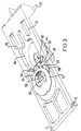
- the control 2 can then be fixed in position on the plate 202 by turning over the tongues 214 into the grooves 152. This assembly may then be mounted in the base of a liquid heating vessel, as shown in Figures 7 and 8.
- a plastics liquid heating vessel 300 is provided with an inwardly facing flange 302 in its base.
- a plurality of mounting bosses 304 are provided on the outer edge of the flange 302, adjacent the lower wall 306 of the vessel 300.
- Each boss 304 has a bore 308 for receiving a fastener such as a self tapping screw 310.
- a raised ring 312 Radially inwardly of the bosses 304 is a raised ring 312 against which the periphery of the heater plate 202 rests. A seal 314 is compressed between the flange 302 and the plate 202 inwardly of the ring 312.
- a bore 150 of the control body 4 engages over a boss 304.
- the lower edge 151 of the bore 150 engages on the plate 202 and when screwed down by the fastener 310 will clamp the plate 202 to the flange 304 via the seal 312.
- the boss 304 provides a significant depth of material into which the fastener 310 can be screwed, thereby improving retention of the heater 200 on the vessel 300.
- the trip lever 6 is in a position in which the movable contacts 116, 118 of the control unit 2 resiliently engage the fixed contacts 204, 206 of the heater 200.
- the overheat sensitive bimetallic actuator 42 is lightly biased into contact with a portion 216 of the heater 200, by the spring 48 and the boiling sensitive actuator lightly biased into contact with the base 128 of the copper plate 126, which is itself in intimate thermal contact with the bottom of the sump 210.
- the trip lever 6 ends up in the position shown in Figure 6 from which it will be seen that not only have the contacts opened, but also the actuator 44 has moved out of thermal contact with the plate 126. This allows the actuator 44 to cool and assume its original curvature relatively quickly, thereby facilitating rapid resetting of the control which can be achieved through moving the knob 26 upwardly. Rapid resetting of the control after boiling is also facilitated by the copper plate 126 which acts as a radiator drawing heat out of the sump 210. This allows the sump temperature to drop relatively quickly so that when the reset actuator 42 is brought back into contact with the plate 126, it does not operate once again.
- the temperature of the heater 200 will rise rapidly. Heat will be transmitted to the overheat actuator 42 from the heater region 216 and at a predetermined temperature (higher than that of the boiling sensitive actuator 42) the actuator 42 will reverse its curvature with a snap action. A peripheral part of the actuator will react against the heater plate 202 causing another part of the actuator to engage a part of the mounting pillar 44, to lift the trip lever 6 past the over centre position of the C-spring 12, to open the contacts, as described above.
- the control may be reset once the actuator 40 and heater 200 have cooled sufficiently. As will be seen from Figure 6, the actuator 42 is lifted out of contact with the heater 200 thereby accelerating its resetting.
- the apertures 160, 162 in the cover plate 8 surround the contact pairs so that when the contacts make and break, the surrounding parts of the heater and control are shielded to some degree from any arcing which may occur. Furthermore, the cylindrical wall on the cover plate 8 will prevent arcing to the sump 210.
- a third level of protection, or back up protection, operable in the event that the overheat protection described above fails to operate may be provided in the heater itself. This may be achieved, for example, by providing sections of the track which will rupture preferentially in a severe overheat condition. Alternatively, glass bridges or a glass covering may be provided between respective terminal sections of the track, these bridges becoming conductive at higher temperatures thereby acting to short out the track.
Description
Claims (7)
- A thermally sensitive control unit (2) for interrupting the electrical supply to a thick film electric heater (200) forming, or forming a part of the base of a water boiling vessel in the event of said heater overheating, characterised in that said control unit comprises a thermally sensitive bimetallic actuator (42) mounted to the control unit by a resilient carrier (48), the actuator being mounted to and carried by said carrier and said carrier being mounted to a mounting location on said control unit such that in use the actuator is resiliently biased against said heater by said carrier so as to accommodate deformation of the heater during operation and relative movement of the mounting location and the heater, said resilient bias being light so as not adversely to interfere with the operation of the actuator.
- A control unit as claimed in claim 1 wherein the resilient carrier comprises a leaf spring.
- A control unit as claimed in claim 1 wherein the resilient carrier comprises a frame-like spring.
- A heater assembly in or for a liquid heating apparatus comprising a thick film heater (200) and the thermally sensitive control unit for the heater as claimed in claim 1, 2 or 3, said heater having a resistive heating track (204) having an electrical contact (206, 208) through which the electrical supply may be conducted to the track, and said control having a movable electrical contact (116, 118) which engages with the track contact, and which, upon operation of the control, moves out of engagement with the track contact to interrupt the electrical supply to the track.
- An assembly or control unit as claimed in any preceding claim wherein the actuator is mounted such that the actuator engages with the heater substantially around the whole periphery of the actuator.
- An assembly or control unit as claimed in any preceding claim wherein said actuator comprises a snap-acting bimetallic actuator.
- An assembly or control unit as claimed in any preceding claim wherein said thermally sensitive actuator is movably mounted with respect to a control body for engagement with a portion of the heater such that upon operation of the actuator, the actuator is moved out of thermal contact with that portion of the heater.
Applications Claiming Priority (3)
| Application Number | Priority Date | Filing Date | Title |
|---|---|---|---|
| GB9703273A GB2322274B (en) | 1997-02-17 | 1997-02-17 | Controls for electric heaters |
| GB9703273 | 1997-02-17 | ||
| PCT/GB1998/000489 WO1998036616A1 (en) | 1997-02-17 | 1998-02-17 | Electric heaters |
Publications (2)
| Publication Number | Publication Date |
|---|---|
| EP1013145A1 EP1013145A1 (en) | 2000-06-28 |
| EP1013145B1 true EP1013145B1 (en) | 2003-02-05 |
Family
ID=10807812
Family Applications (1)
| Application Number | Title | Priority Date | Filing Date |
|---|---|---|---|
| EP98904302A Expired - Lifetime EP1013145B1 (en) | 1997-02-17 | 1998-02-17 | Electric heaters |
Country Status (6)
| Country | Link |
|---|---|
| EP (1) | EP1013145B1 (en) |
| CN (3) | CN2387691Y (en) |
| AU (1) | AU6224498A (en) |
| DE (1) | DE69811246T2 (en) |
| GB (1) | GB2322274B (en) |
| WO (1) | WO1998036616A1 (en) |
Families Citing this family (15)
| Publication number | Priority date | Publication date | Assignee | Title |
|---|---|---|---|---|
| GB2334190B (en) * | 1997-11-18 | 2001-12-12 | Otter Controls Ltd | Improvements relating to thermal controls for electric heating elements |
| GB2351846B (en) | 1998-03-17 | 2002-03-13 | Strix Ltd | Thermally sensitive controls |
| GB2344744B (en) | 1998-11-26 | 2001-07-25 | Strix Ltd | Electrical beverage making apparatus |
| WO2000036956A1 (en) * | 1998-12-21 | 2000-06-29 | Seb S.A. | Heating base for electric household appliance for heating liquids |
| FR2787310B1 (en) * | 1998-12-21 | 2001-01-26 | Seb Sa | ELECTRIC HOUSEHOLD APPLIANCE FOR HEATING LIQUIDS, ESPECIALLY ELECTRIC PISTON COFFEE MAKER |
| GB2346540B (en) * | 1999-02-08 | 2002-10-09 | Otter Controls Ltd | Improvements relating tp electrically heated vessels |
| GB2378818B (en) * | 1999-02-11 | 2003-06-11 | Otter Controls Ltd | Improvements relating to control of electric heating elements |
| GB2353457B (en) * | 1999-08-13 | 2004-08-25 | Strix Ltd | Electric heaters |
| GB2372421B (en) * | 2001-02-19 | 2005-07-27 | Strix Ltd | Thermally sensitive controls |
| GB2377608B (en) * | 2001-04-23 | 2005-09-07 | Strix Ltd | Electric heaters |
| GB2398995B (en) * | 2003-03-05 | 2005-02-16 | Strix Ltd | Mounting components to electric heaters for liquid heating appliances |
| NL1022942C2 (en) * | 2003-03-17 | 2004-09-20 | Ferro Techniek Holding Bv | Device is for heating water held in container, to which heating element is connected together with a fluid chamber |
| US7901475B2 (en) * | 2008-01-18 | 2011-03-08 | Gm Global Technology Operations, Inc. | Diesel particulate filter with zoned resistive heater |
| CN111903023A (en) * | 2018-04-04 | 2020-11-06 | Abb瑞士股份有限公司 | Slide-in compartment for a module |
| WO2019192690A1 (en) * | 2018-04-04 | 2019-10-10 | Abb Schweiz Ag | Arrangement comprising a compartment and a slide-in module |
Family Cites Families (12)
| Publication number | Priority date | Publication date | Assignee | Title |
|---|---|---|---|---|
| US3715567A (en) * | 1970-11-04 | 1973-02-06 | R Mandziak | Liquid heating assembly |
| GB1321825A (en) * | 1970-12-16 | 1973-07-04 | Ass Elect Ind | Terminal housings for electrically heated vessels |
| FR2470575B1 (en) * | 1979-11-28 | 1986-02-14 | Moulinex Sa | ELECTRIC COOKING APPLIANCE |
| GB2079057B (en) * | 1980-06-18 | 1984-10-10 | Hobbs R Ltd | An electric liquid heating appliance |
| US4555686A (en) * | 1984-05-29 | 1985-11-26 | Texas Instruments Incorporated | Snap-acting thermostatic switch assembly |
| NL8801182A (en) * | 1987-10-01 | 1989-05-01 | Interconnection B V | HEATING ELEMENT. |
| GB2236220B (en) * | 1989-09-01 | 1994-06-29 | Otter Controls Ltd | Improvements relating to electrical appliances |
| NL8902238A (en) * | 1989-09-06 | 1991-04-02 | Interconnection B V | HEATING ELEMENT AND SYSTEM INCLUDING SUCH A HEATING ELEMENT. |
| GB9302965D0 (en) * | 1993-02-15 | 1993-03-31 | Strix Ltd | Immersion heaters |
| DE69531618D1 (en) * | 1994-06-09 | 2003-10-02 | Strix Ltd | CONTROL DEVICES FOR LIQUID HEATING DEVICES |
| CN1154782A (en) * | 1994-06-09 | 1997-07-16 | 施特里克斯有限公司 | Liquid heating vessels |
| GB9524176D0 (en) * | 1995-11-27 | 1996-01-31 | Otter Controls Ltd | Improvements relating to electrically powered liquid heating appliances and controls therefor |
-
1997
- 1997-02-17 GB GB9703273A patent/GB2322274B/en not_active Expired - Fee Related
-
1998
- 1998-02-17 EP EP98904302A patent/EP1013145B1/en not_active Expired - Lifetime
- 1998-02-17 AU AU62244/98A patent/AU6224498A/en not_active Abandoned
- 1998-02-17 CN CN98213974U patent/CN2387691Y/en not_active Expired - Lifetime
- 1998-02-17 CN CN 200410049525 patent/CN1558700B/en not_active Expired - Fee Related
- 1998-02-17 CN CN 98802628 patent/CN1258303C/en not_active Expired - Fee Related
- 1998-02-17 WO PCT/GB1998/000489 patent/WO1998036616A1/en active IP Right Grant
- 1998-02-17 DE DE69811246T patent/DE69811246T2/en not_active Expired - Lifetime
Also Published As
| Publication number | Publication date |
|---|---|
| DE69811246D1 (en) | 2003-03-13 |
| CN1248383A (en) | 2000-03-22 |
| GB2322274A (en) | 1998-08-19 |
| DE69811246T2 (en) | 2003-09-25 |
| CN1558700A (en) | 2004-12-29 |
| GB9703273D0 (en) | 1997-04-09 |
| CN1558700B (en) | 2010-12-01 |
| WO1998036616A1 (en) | 1998-08-20 |
| CN1258303C (en) | 2006-05-31 |
| CN2387691Y (en) | 2000-07-12 |
| GB2322274B (en) | 1999-01-13 |
| AU6224498A (en) | 1998-09-08 |
| EP1013145A1 (en) | 2000-06-28 |
Similar Documents
| Publication | Publication Date | Title |
|---|---|---|
| EP1013145B1 (en) | Electric heaters | |
| US6080968A (en) | Liquid heating vessels | |
| US5946448A (en) | Methods of assembling immersion heaters with heating elements in the form of printed circuit tracks | |
| EP0845957B1 (en) | Liquid heating vessels | |
| AU689811B2 (en) | Improvements relating to electrical heating elements and controls therefor | |
| EP0994666B1 (en) | Thick Film Electric Heaters | |
| GB2283156A (en) | Association of heating element and thermal control | |
| US4510375A (en) | Electric immersion heater assembly for liquid heating appliances | |
| EP1223790B1 (en) | Liquid heating vessels | |
| GB2292841A (en) | Contact arrangement for a liquid heating vessel | |
| WO1995019129A1 (en) | Water heating apparatus | |
| EP1173863B1 (en) | Improvements relating to thermally-responsive controls | |
| EP1642309B1 (en) | Improvements relating to thermal control units | |
| GB2333901A (en) | Control device | |
| EP0846329B1 (en) | Heat transfer element for thermal controls | |
| GB2324015A (en) | Spaced bimetal actuators operating at same temperature | |
| WO1997021374A1 (en) | Controls for liquid heating vessels | |
| GB2354927A (en) | Water heating element with adjustable resistance track associated with bimetal control | |
| GB2252875A (en) | Liquid boiling vessels | |
| GB2305341A (en) | Mounting immersion heaters to control devices | |
| WO1998001874A1 (en) | Improvements relating to thermally responsive electric switches |
Legal Events
| Date | Code | Title | Description |
|---|---|---|---|
| PUAI | Public reference made under article 153(3) epc to a published international application that has entered the european phase |
Free format text: ORIGINAL CODE: 0009012 |
|
| 17P | Request for examination filed |
Effective date: 19990917 |
|
| AK | Designated contracting states |
Kind code of ref document: A1 Designated state(s): DE ES FR GB IT NL |
|
| 17Q | First examination report despatched |
Effective date: 20010115 |
|
| GRAH | Despatch of communication of intention to grant a patent |
Free format text: ORIGINAL CODE: EPIDOS IGRA |
|
| GRAH | Despatch of communication of intention to grant a patent |
Free format text: ORIGINAL CODE: EPIDOS IGRA |
|
| GRAA | (expected) grant |
Free format text: ORIGINAL CODE: 0009210 |
|
| AK | Designated contracting states |
Designated state(s): DE ES FR GB IT NL |
|
| REG | Reference to a national code |
Ref country code: GB Ref legal event code: FG4D |
|
| REF | Corresponds to: |
Ref document number: 69811246 Country of ref document: DE Date of ref document: 20030313 Kind code of ref document: P |
|
| ET | Fr: translation filed | ||
| PG25 | Lapsed in a contracting state [announced via postgrant information from national office to epo] |
Ref country code: ES Free format text: LAPSE BECAUSE OF FAILURE TO SUBMIT A TRANSLATION OF THE DESCRIPTION OR TO PAY THE FEE WITHIN THE PRESCRIBED TIME-LIMIT Effective date: 20030828 |
|
| PLBE | No opposition filed within time limit |
Free format text: ORIGINAL CODE: 0009261 |
|
| STAA | Information on the status of an ep patent application or granted ep patent |
Free format text: STATUS: NO OPPOSITION FILED WITHIN TIME LIMIT |
|
| 26N | No opposition filed |
Effective date: 20031106 |
|
| REG | Reference to a national code |
Ref country code: GB Ref legal event code: 732E |
|
| PGFP | Annual fee paid to national office [announced via postgrant information from national office to epo] |
Ref country code: IT Payment date: 20080221 Year of fee payment: 11 |
|
| PG25 | Lapsed in a contracting state [announced via postgrant information from national office to epo] |
Ref country code: IT Free format text: LAPSE BECAUSE OF NON-PAYMENT OF DUE FEES Effective date: 20090217 |
|
| PGFP | Annual fee paid to national office [announced via postgrant information from national office to epo] |
Ref country code: DE Payment date: 20110216 Year of fee payment: 14 Ref country code: FR Payment date: 20110222 Year of fee payment: 14 Ref country code: NL Payment date: 20110225 Year of fee payment: 14 |
|
| PGFP | Annual fee paid to national office [announced via postgrant information from national office to epo] |
Ref country code: GB Payment date: 20110207 Year of fee payment: 14 |
|
| REG | Reference to a national code |
Ref country code: NL Ref legal event code: V1 Effective date: 20120901 |
|
| GBPC | Gb: european patent ceased through non-payment of renewal fee |
Effective date: 20120217 |
|
| REG | Reference to a national code |
Ref country code: FR Ref legal event code: ST Effective date: 20121031 |
|
| REG | Reference to a national code |
Ref country code: DE Ref legal event code: R119 Ref document number: 69811246 Country of ref document: DE Effective date: 20120901 |
|
| PG25 | Lapsed in a contracting state [announced via postgrant information from national office to epo] |
Ref country code: FR Free format text: LAPSE BECAUSE OF NON-PAYMENT OF DUE FEES Effective date: 20120229 Ref country code: GB Free format text: LAPSE BECAUSE OF NON-PAYMENT OF DUE FEES Effective date: 20120217 Ref country code: NL Free format text: LAPSE BECAUSE OF NON-PAYMENT OF DUE FEES Effective date: 20120901 |
|
| PG25 | Lapsed in a contracting state [announced via postgrant information from national office to epo] |
Ref country code: DE Free format text: LAPSE BECAUSE OF NON-PAYMENT OF DUE FEES Effective date: 20120901 |